5
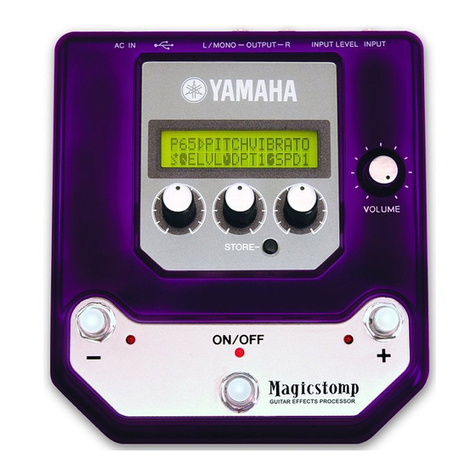
Amp Simulator
DG Series amp sound. Mainly used for direct connection to power amp.
Speaker simulator allows direct recording.
Chorus
Chorus effect.
Symphonic
Symphonic effect.
Parameter Display Range Description
Amp Type AMP
Heavy1, Heavy2, Lead1, Lead2,
Drive1, Drive2, Crunch1,
Crunch2, Clean1, Clean2, Solid
Amp type
Gain GAIN 0.0 to 10.0 Adjusts the amount of distortion
Master MSTR 0.0 to 10.0 Adjusts the volume
Tone TONE 0.0 to 10.0 Adjusts the tone
Treble TRE 0.0 to 10.0 Adjusts level of high range frequencies
High Middle HMID 0.0 to 10.0 Adjusts level of upper mid frequencies
Low Middle LMID 0.0 to 10.0 Adjusts level of lower mid frequencies
Bass BASS 0.0 to 10.0 Adjusts level of low frequencies
Presence PRE 0.0 to 10.0 Adjusts level of extremely high frequencies
Speaker
Simulator SP
Off, American 412, British 412,
Modern 412, YAMAHA 412, Hybrid
412, American 212, British 212,
Modern 212, YAMAHA 212, Hybrid
212, American 112, Modern 112,
YAMAHA 112, Hybrid 112, 410,
210
When using a line connection to connect directly to a mixer, this can be
used to simulate the natural characteristics of a speaker giving the tone
a more natural sound
N. G. Threshold NGTH 0.0 to 10.0 Level at which the noise gate activates
N. G. Attack NGAT 0 to 120 ms Time required for the noise gate to open after signal exceeds threshold
N. G. Hold NGHL 0.02 to 2040 ms Time noise gate stays open
N. G. Decay NGDC 6 to 44500 ms Time required for the noise gate to close after signal goes below thresh-
old
Parameter Display Range Description
Wave WAVE Sine, Triangle Modulation waveform
Freq. FREQ 0.05 to 40.00 Hz Modulation speed
AM Depth AMDP 0 to 100% Amplitude modulation depth
PM Depth PMDP 0 to 100% Pitch modulation depth
Mod. Delay MDT 0.0 to 500.0 ms Modulation delay time
LSH Freq. LSHF 21.2 Hz to 8.00 kHz Low shelving filter frequency
LSH Gain LSHG –12.0 to +12.0 dB Low shelving filter gain
EQ Freq. EQ.F 100 Hz to 8.00 kHz EQ (peaking type) frequency
EQ Gain EQ.G –12.0 to +12.0 dB EQ (peaking type) gain
EQ Q EQ.Q 10.0 to 0.10 EQ (peaking type) bandwidth
HSH Freq. HSHF 50.0 Hz to 16.0 kHz High shelving filter frequency
HSH Gain HSHG –12.0 to +12.0 dB High shelving filter gain
Mix MIX 0 to 100% Mix level
Parameter Display Range Description
Wave WAVE Sine, Triangle Modulation waveform
Freq. FREQ 0.05 to 40.00 Hz Modulation speed
Depth DPT 0 to 100% Modulation depth
Mod. Delay MDT 0.0 to 500.0 ms Modulation delay time
LSH Freq. LSHF 21.2 Hz to 8.00 kHz Low shelving filter frequency
LSH Gain LSHG –12.0 to +12.0 dB Low shelving filter gain
EQ Freq. EQ.F 100 Hz to 8.00 kHz EQ (peaking type) frequency
EQ Gain EQ.G –12.0 to +12.0 dB EQ (peaking type) gain
EQ Q EQ.Q 10.0 to 0.10 EQ (peaking type) bandwidth
HSH Freq. HSHF 50.0 Hz to 16.0 kHz High shelving filter frequency
HSH Gain HSHG –12.0 to +12.0 dB High shelving filter gain
Mix MIX 0 to 100% Mix level
