Yamaha YSP-1 User manual

SERVICE MANUAL
DIGITAL SOUND PROJECTOR
YSP-1
■CONTENTS
TO SERVICE PERSONNEL .......................................... 2
FRONT PANEL .............................................................. 3
REAR PANELS .............................................................. 3
REMOTE CONTROL PANELS ...................................... 4
SPECIFICATIONS / 参考仕様 ........................................ 4
INTERNAL VIEW ........................................................... 5
SET MENU TABLE ........................................................ 6
DISASSEMBLY PROCEDURES/分解手順 ........... 7~12
UPDATING FIRMWARE/
ファームウェアの書き込み ..................................... 13~19
SELF DIAGNOSIS FUNCTION (DIAG)/
自己診断機能(ダイアグ)..................................... 20~36
DISPLAY DATA ........................................................... 37
IC DATA ................................................................. 38~39
BLOCK DIAGRAM ....................................................... 40
PRINTED CIRCUIT BOARD .................................. 41~49
PIN CONNECTION DIAGRAM .................................... 50
SCHEMATIC DIAGRAM ........................................ 51~54
PARTS LIST ........................................................... 55~66
REMOTE CONTROL.................................................... 67
100931
IMPORTANT NOTICE
This manual has been provided for the use of authorized YAMAHA Retailers and their service personnel.
It has been assumed that basic service procedures inherent to the industry, and more specifically YAMAHA Products, are already
known and understood by the users, and have therefore not been restated.
WARNING: Failure to follow appropriate service and safety procedures when servicing this product may result in personal
injury, destruction of expensive components, and failure of the product to perform as specified. For these reasons,
we advise all YAMAHA product owners that any service required should be performed by an authorized
YAMAHA Retailer or the appointed service representative.
IMPORTANT: The presentation or sale of this manual to any individual or firm does not constitute authorization, certification or
recognition of any applicable technical capabilities, or establish a principle-agent relationship of any form.
The data provided is believed to be accurate and applicable to the unit(s) indicated on the cover. The research, engineering, and
service departments of YAMAHA are continually striving to improve YAMAHA products. Modifications are, therefore, inevitable
and specifications are subject to change without notice or obligation to retrofit. Should any discrepancy appear to exist, please
contact the distributor's Service Division.
WARNING: Static discharges can destroy expensive components. Discharge any static electricity your body may have
accumulated by grounding yourself to the ground buss in the unit (heavy gauge black wires connect to this buss).
IMPORTANT: Turn the unit OFF during disassembly and part replacement. Recheck all work before you apply power to the unit.
YSP-1
P.O.Box 1, Hamamatsu, Japan
'05.01

YSP-1
2
YSP-1
WARNING: CHEMICAL CONTENT NOTICE!
The solder used in the production of this product contains LEAD. In addition, other electrical/electronic and/or plastic (where
applicable) components may also contain traces of chemicals found by the California Health and Welfare Agency (and
possibly other entities) to cause cancer and/or birth defects or other reproductive harm.
DO NOT PLACE SOLDER, ELECTRICAL/ELECTRONIC OR PLASTIC COMPONENTS IN YOUR MOUTH FOR ANY REA-
SON WHATSOEVER!
Avoid prolonged, unprotected contact between solder and your skin! When soldering, do not inhale solder fumes or expose
eyes to solder/flux vapor!
If you come in contact with solder or components located inside the enclosure of this product, wash your hands before
handling food.
WALL
OUTLET
EQUIPMENT
UNDER TEST
AC LEAKAGE
TESTER OR
EQUIVALENT
INSULATING
TABLE
■TO SERVICE PERSONNEL
1. Critical Components Information
Components having special characteristics are marked s
and must be replaced with parts having specifications equal
to those originally installed.
2. Leakage Current Measurement (For 120V Models Only)
When service has been completed, it is imperative to verify
that all exposed conductive surfaces are properly insulated
from supply circuits.
●Meter impedance should be equivalent to 1500 ohms
shunted by 0.15µF.
●Leakage current must not exceed 0.5mA.
●Be sure to test for leakage with the AC plug in both polarities.
About Lead Free Solder / 無鉛ハンダについて
Side A
Side B
SMT
REFLOW
Process
MI
FLOW
Process
Solder Dip
無鉛ハンダにはいくつかの種類がありますが、修理時には
下記のような無鉛ハンダの使用を推奨します。
・Sn+Ag+Cu(錫+銀+銅)
・Sn+Cu(錫+銅)
・Sn+Zn+Bi(錫+亜鉛+ビスマス)
注意:
① 無鉛ハンダの融点温度は通常の鉛入りハンダに比べ30
〜40℃程度高くなっていますので、それぞれのハンダ
に合ったハンダごてをご使用ください。
② 鉛入りハンダを使わざるを得ない場合は、あらかじめ交
換する部品端子部やその周辺部の無鉛ハンダをすべて取
り除くか、あるいは無鉛ハンダと鉛入りハンダが十分に
溶けた状態となるようにハンダ付けしてください。
Among some types of lead free solder currently available,
it is recommended to use one of the following types for the
repair work.
• Sn + Ag + Cu (tin + silver + copper)
• Sn + Cu (tin + copper)
• Sn + Zn + Bi (tin + zinc + bismuth)
Caution:
1. As the melting point temperature of the lead free solder
is about 30°C to 40°C (50°F to 70°F) higher than that of
the lead solder, be sure to use a soldering iron suitable
to each solder.
2. If lead solder must be used, be sure to remove lead free
solder from each terminal section of the parts to be
replaced and from the area around it completely before
soldering, or make sure that the lead free solder and
lead solder melt together fully.
The P.C.B.s installed in this unit are soldered using the
following solder.
本機に搭載されている基板のハンダ付けに使用されている
ハンダは下記の通りです。
DSP P.C.B.
AMP P.C.B.
INPUT P.C.B.
SIDE A / A面
Lead Free Solder / 無鉛ハンダ
–
SIDE B / B面
Lead Free Solder / 無鉛ハンダ

YSP-1
3
YSP-1
■FRONT PANEL
BOTTOM VIEW
■REAR PANELS
U, C models T model
K model
B, G models L model J model
R model
A model
J model only

YSP-1
4
YSP-1
■REMOTE CONTROL PANELS ■SPECIFICATIONS / 参考仕様
■Audio Section/オーディオ部
Minimum RMS Output Power (Power Amp. Section)/定格出力(パ
ワーアンプ部)
Woofer [100Hz, 10%THD, 4 ohms] ................................. 20W x 2
Tweeter [1kHz, 10%THD, 10 ohms] ................................ 2W x 40
Input Jack/入力端子
AUX, TV ................................................................ 1V / 32 k-ohms
Output Jack/出力端子
VIDEO ................................................................. 1Vp-p / 75 ohms
Subwoofer .............................. 2V / 75 k-ohms (Input 1V / 100Hz)
Driver / スピーカーユニット
Woofer ......................................................... 4.5" (11 cm) cone x 2
Magnetic Shielding Type
Tweeter ....................................................... 1.5" (4 cm) cone x 40
Magnetic Shielding Type
■General/総合
Power Supply/電源電圧
U, C models ........................................................ AC 120 V, 60 Hz
R model .................................................. AC 110-120 V, 50/60 Hz
T model ............................................................... AC 220 V, 50 Hz
K model ............................................................... AC 220 V, 60 Hz
A model ............................................................... AC 240 V, 50 Hz
B, G models ........................................................ AC 230 V, 50 Hz
L model ................................................... AC 220-240 V, 50/60 Hz
J model ........................................................... AC 100V, 50/60 Hz
Power Consumption/消費電力
U, C, R, T, K, A, B, G, L models ........................................... 50 W
J model .................................................................................. 55 W
Standby Power Consumption (reference data)/待機時消費電力
(参考値)
.................................................................................. 0.5 W or less
Dimensions/寸法 (W x H x D)
.................... 1030 x 194 x 118 mm (40-9/16" x 7-5/8" x 4-11/16")
Weight/質量
....................................................................... 13 kg (34 lbs. 3 oz.)
Accessories/付属品
Remote Control, Batteries (Manganese Dry), Power Cable,
Video Pin Cable, Audio Pin Cable, Digital Audio Pin Cable,
Optical Cable, Fastener x 4, Cable Clip
U .......... U.S.A. model C ...... Canadian model
R .......... General model T ....... Chinese model
K .......... Korean model A ...... Austrarian model
B .......... British model G ...... European model
L ........... Singapore model J ....... Japanese model
* Specifications are subject to change without notice due to product
improvements.
※ 参考仕様および外観は予告なく変更されることがあります。
U, C, R, T, K, A, B, G, L models
J model

YSP-1
5
■INTERNAL VIEW
3 4
6 7
1DRIVER, WOOFER
2DRIVER, TWEETER
3INPUT (3) P.C.B.
4INPUT (4) P.C.B.
5AMP P.C.B.
6INPUT (2) P.C.B.
7DSP P.C.B.
8
SWITCHING POWER SUPPLY UNIT
9INPUT (5) P.C.B.
4INPUT (1) P.C.B.
FRONT VIEW
REAR VIEW
REAR UNIT
2
2 11
5
8 9 0
5
• DIMENSIONS/寸法図
118 (4-11/16")
194 (7-5/8")
1030 (40-9/16")
Unit : mm (inch)
単位: mm(インチ)
Manufactured under license from Dolby Laboratories.
“Dolby”, “Pro Logic”, and the double-D symbol are trademarks of
Dolby Laboratories.
ドルビーラボラトリーズからの実施権により製造されています。「ドル
ビー」、「PROLOGIC」およびダブルD記号 は、ドルビーラボラト
リーズの商標です。
“DTS”, and “Neo:6” are trademarks of Digital Theater Systems, Inc.
DTS、DTSデジタルサラウンドおよびNeo:6はデジタルシアターシス
テムズの登録商標です。
AACロゴマーク はドルビーラボラトリーズの商標です。
Manufactured under license from 1 Ltd. world-wide patents applied
for.
The “ ” logo and “Digital Sound Projector” are trademarks of 1
Ltd.
本デジタル・サウンド・プロジェクターは、全世界へ特許申請中の英
国1Ltdからライセンス許諾を得た製品です。
ロゴと、デジタル・サウンド・プロジェクターは1Ltdの商標
です。

YSP-1
6
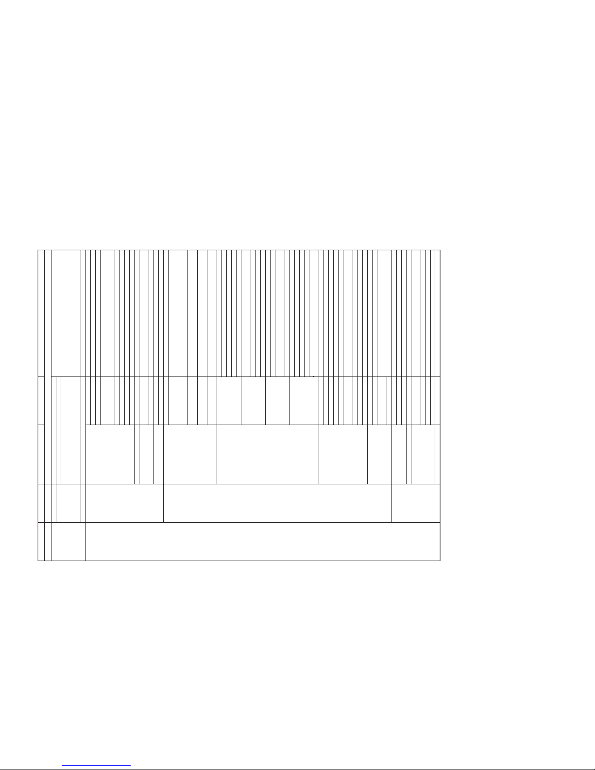
■SET MENU TABLE / セットメニュー
*1... Distance between this unit and floor. / 本機と床との距離
*2... Distance in the lateral direction of the room (length of the wall on the left side of the user) / 部屋の横方向の距離(ユーザーの左側壁の距離)
*3... Distance in the longitudinal direction of the room (length of the wall on the right side of the user) / 部屋の縦方向の距離(ユーザーの右側壁の距離)
*4... Distance from this unit to the user / 本機からユーザーまでの距離
*5... Distance from the left wall to the user (not applicable when set in a room corner) / 左壁からユーザーまでの距離(コーナー時は無し)
*6... Test tone output for **ANGLE, FORCUS ・・・ only (Band pass ON) / **ANGLE,FORCUS・・・のみテストトーン出力(バンドパス入)
*7... Priority given to COAXIAL when set to the same input. / 同じ入力に設定した場合は、COAXIAL優先
*8... OFF = Brightness of STANDARD DIMMER / OFF=STANDARDDIMMERの明るさ
*9... + direction is downward. / +方向は下
Dialogue
SWFR, FRONT
80, [100], 120 (Hz)
-20 ~ [0] (dB)
0.3 ~ 24.0 [3.0] m, 0.1 step
1.0 ~ 80.0 [7.0] ft, 0.5 step
· · · · · · · ¦· · · · · · · *Test tone output
MIN, STD, [MAX]
[MUTE], -20dB
[0] ~ 160mS, 1 step
MAIN, SUB, ALL
· · · · ¦· · · · -12.0 ~ 0 ~ +12.0 dB, 0.5 step
[WALL], CORNER
0.0 ~ 3.0m (0.1 step)
0.0 ~ 10.0ft (0.5 step)
2.0 ~ 12.0m (0.1 step)
6.5 ~ 40.0ft (0.5 step)
2.0 ~ 12.0m (0.1 step)
6.5 ~ 40.0ft (0.5 step)
2.0 ~ 9.0m (0.1 step)
6.5 ~ 30.0ft (0.5 step)
0.6 ~ 11.4m (0.1 step)
2.0 ~ 38.0ft (0.5 step)
H.ANGLE FL -90 ~ +90deg, 1 step
H.ANGLE FR -90 ~ +90deg, 1 step
H.ANGLE C -90 ~ +90deg, 1 step
H.ANGLE SL -90 ~ +90deg, 1 step
H.ANGLE SR -90 ~ +90deg, 1 step
V.ANGLE.FL -90 ~ +90deg, 1 step
V.ANGLE.FR -90 ~ +90deg, 1 step
V.ANGLE.C -90 ~ +90deg, 1 step
V.ANGLE.SL -90 ~ +90deg, 1 step
V.ANGLE.SR -90 ~ +90deg, 1 step
DIST FL 0.3 ~ 24.0m, 0.1 step/1.0 ~ 80.0ft, 0.5 step
DIST FR 0.3 ~ 24.0m, 0.1 step/1.0 ~ 80.0ft, 0.5 step
DIST C 0.3 ~ 24.0m, 0.1 step/1.0 ~ 80.0ft, 0.5 step
DIST SL 0.3 ~ 24.0m, 0.1 step/1.0 ~ 80.0ft, 0.5 step
DIST SR 0.3 ~ 24.0m, 0.1 step/1.0 ~ 80.0ft, 0.5 step
F.L. FL -1.0 ~ +13.0m, 0.1 step/-3.5 ~ +43.5ft, 0.5 step
F.L. FR -1.0 ~ +13.0m, 0.1 step/-3.5 ~ +43.5ft, 0.5 step
F.L. C -1.0 ~ +13.0m, 0.1 step/-3.5 ~ +43.5ft, 0.5 step
F.L. SL -1.0 ~ +13.0m, 0.1 step/-3.5 ~ +43.5ft, 0.5 step
F.L. SR -1.0 ~ +13.0m, 0.1 step/-3.5 ~ +43.5ft, 0.5 step
[STANDARD], LIVE, DEAD
· · · · ¦· · · · -12.0 ~ [0] ~ +12.0 dB, 0.5 step
[OFF], ON
L ¦· · · · · · · · C 0 ~ 95[%] (5% step) *Test tone output
C · · · · · · · · ¦R 0 ~ 95[%] (5% step) *Test tone output
USER1, USER2, USER3
[TV], VCR
DVD, [AUX]
[DVD], AUX
TV, DVD, AUX, VCR
-2, -1, [OFF]
DISPLAY OFF, -3, -2, -1, [OFF]
-5 ~ [0] ~ +5, 1 Step
BLUE, GRAY
MEMORY
EASY SETUP
MANUAL SETUP
LOAD
ROOM TYPE ?
SP POSITION ?
ROOM SIZE ?
SETUP OK ?
1 SOUND MENU
2 BEAM MENU
3 INPUT MENU
4 OPTION MENU
USER1, USER2, USER3
SQUARE, REC-TANGLE
SQUARE: LEFT, CENTER, RIGHT, CORNER
RECTANGLE : WIDE/LEFT, CENTER, RIGHT
CORNER/LEFT, RIGHT
NARROW/LEFT, CENTER, RIGHT
SMALL, MID, LARGE
NO, YES
A) SUBWOOFER SET
B) SPEAKER LEVEL
C) DYNAMIC RANGE
D) AUDIO SET
E) TONE CONTROL
A) PARAMETER
B) BEAM ADJ
C) ROOM EQ
D) BEAM TONE CONTROL
E) IMAGE LOCATION
F) MEMORY
A) I/O ASSIGNMENT
B) INPUT MODE
C) INPUT RENAME
A) DISPLAY SET
B) UNIT SET
BASS OUT
CROSS OVER
LFE LEVEL
DISTANCE
FR
C
SL
SR
SWFR
MAX
MUTE LEVEL
AUDIO DELAY
DUAL MONO
TREBLE
BASS
SP POSITION
SP HEIGHT
ROOM WIDTH
(C : LEFT WALL)
ROOM LENGTH
(C : RIGHT WALL)
USER POSITION
TO L WALL
a) HORIZ. ANGLE
b) VERTICAL ANGLE
c) DISTANCE
d) FOCAL LENGTH
STANDARD
TREBLE FL
BASS FL
TREBLE FR
BASS FR
TREBLE C
BASS C
TREBLE SL
BASS SL
TREBLE SR
BASS SR
OFF
LEFT
RIGHT
SAVE
LOAD
OPTICAL IN (1)
OPTICAL IN (2)
COAXIAL IN (3)
AUTO, LAST
STANDARD DIMMER
AUTO DIMMER
OSD SHIFT
OSD BACK COLOR
METERS, FEET
*1
*2
*3
*4
*5
*6
*7
*7
*8
*9
CATEGORY MAIN MENU SUB MENU SELECT MENU VALUE [INITIAL]

YSP-1
7
YSP-1
1
1
1
1
2
Top Panel
Top Panel
Plate/ Top
Fig. 1
1. Removal of Top Panels and Plate/Top
a. Remove 8 screws (1). (Fig. 1)
b. Remove 2 Top Panels.
c. Remove 2 screws (2). (Fig. 1)
d. Remove the Plate/Top.
1. トップパネル、プレート/トップの外し方
分解・組立時の注意:
■DISASSEMBLY PROCEDURES / 分解手順
(Remove parts in the order as numbered.)
Cautions for disassembly and reassembly :
• Disconnect the power cable from the AC outlet.
• Spread soft cloth or the like and perform the work on it.
• Use full care as you may be injured by the front grille
or other part.
• All screws must be tightened securely to prevent air
leakage. Check the number of screws and their
positions when installing them.
• When installing parts, be careful not to have anything
such as cables caught between other parts.
• Make sure that all the removed driver (tweeter) parts
are reinstalled at specified positions.

YSP-1
8
YSP-1
When checking the P.C.B. :
• The Rear Unit removed from the unit does not work
because its grounding is loose. Be sure to connect the
ground of the Rear Unit to the chassis or GND with a
lead wire or the like. (Fig. A)
• Reconnect all cables (connectors) that have been
disconnected.
Be sure to use the extension cable for servicing for the
following section.
DSP P.C.B. CB300 – INPUT (2) P.C.B. CB9 :
MFA27160 (27P 160mm)
DSP P.C.B. CB1, CB2 – AMP P.C.B. CB3 :
MFA18160 (18P 160mm)
• When connecting the cable, use care for the polarity.
2. Removal of Rear Unit
a. Remove 22 screws (3). (Fig. 2)
b. Remove CB7, CB10 and CB14. (Fig. 3)
c. Remove the Rear Unit.
2. リアユニットの外し方
3333
333
3
CB14 CB7 CB10
Rear Unit
P.C.B.チェックをする場合には
Fig. A
Fig. 2
Fig. 3
Rear Unit
Front Panel Unit
DSP P.C.B.
INPUT (CONNECT) P.C.B.
AMP P.C.B.
CB3 CB1
CB300
CB2
CB9
CB3
MFA18160 MFA18160
MFA27160
AMP P.C.B.
Earth (lead wire)

YSP-1
9
YSP-1
3. INPUT(2)P.C.B.の外し方
3. Removal of INPUT (2) P.C.B.
a. Remove 14 screws (4). (Fig. 4)
b. Remove 3 pad L’s. (Fig. 4)
c. Remove the Plate/Shield.
d. Remove 4 screws (5). (Fig. 5)
e. Remove CB7, CB9 and CB302. (Fig. 5)
f. Remove the INPUT (2) P.C.B..
444
44
4
Plate/ Shield
Pad L
Fig. 4
4. DSPP.C.B.、AMPP.C.B.の外し方
4. Removal of DSP P.C.B., AMP P.C.B.
a. Remove 4 screws (6). (Fig. 6)
b. Remove CB3 and CB303. (Fig. 6)
c. Remove DSP P.C.B..
d. Remove 8 screws (7). (Fig. 6)
e. Remove CB1, CB2, CB4, CB5 and CB6. (Fig. 6)
f. Remove AMP P.C.B.s.
5
5
INPUT (2) P.C.B.
CB7
CB9 CB302
CB7
Fig. 5
Fig. 6
6
6
CB1
CB303 CB6 CB1
CB2 CB5 CB4
7
7
7
7
CB6 CB3 CB4CB3 CB2CB5
DSP P.C.B.
AMP P.C.B. AMP P.C.B.

YSP-1
10
YSP-1
5. フロントパネルユニットの外し方
5. Removal of Front Panel Unit
a. Remove 17 screws (8). (Fig. 7)
b. Remove the Front Panel Unit.
c. Remove 2 screws (9). (Fig. 8)
d. Remove the Stopper frame.
8 88 88
Front Panel Unit
9
Stopper Frame
Fig. 8
0 0 0
0 0 0 0
0
TOP
BOTTOM
Fig. 9
6. Removal of Driver (Tweeter)
a. Remove 12 screws (0). (Fig. 9)
b. Remove 4 Supports/DSP.
c. Remove the Sound absorbing material.
d. Remove 2 screws/piece marked (A). (Fig. 11)
e. Remove the Driver (Tweeter).
6. スピーカーユニット(ツイーター)の外し方
Sound Absorber
Support/ DSP
Support/ DSP
Fig. 10
Fig. 7

YSP-1
11
YSP-1
Installation of Driver (Tweeter)
Caution : Make sure that all the removed Driver (tweeter)
parts are reinstalled at specified positions.
(Fig. B)
スピーカーユニット(ツイーター)の取り付け方
注意:
A1
B1
A2
B2
C1
A3
B3
C2
A4
B4
C3
A5
B5
C4
A6
B6
C5
A7
B7
C6
A8
B8
C7
A9
B9
C8
A10
B10
C9
A11
B11
C10
A12
B12
C11
A13
B13
A14
B14
A15
REAR VIEW
Rch side
Lch side
CB1
CB2 CB5 CB6 CB1
CB6 CB5 CB2
A
Fig. 11
Fig. B
Lch side / Lch側
Pin No. / ピンNo. CB1
1 –2
3 –4
5 –6
7 –8
9 –#
A1
B1
A2
A3
A4
C5
B6
C4
B5
C3
A5
A6
A7
B7
A8
B13
C11
B12
C10
B11
A12
A13
A14
B14
A15
A9
B9
A10
B10
A11
C9
C8
C7
B8
C6
B4
C2
B3
C1
B2
CB2 CB5 CB6 CB1 CB2 CB5 CB6
Rch side / Rch側
#: CB1, CB2_10pin CB5, CB6_11pin

YSP-1
12
YSP-1
D
DE
E
B
B
C
C
C
C
Side Cover L
Side Cover R
Plate Side
Plate Side
Plate Cover
Plate Cover
Front Grille
Driver, Woofer
Driver, Woofer
7. Removal of Driver (Woofer)
a. Remove 4 screws (B). (Fig. 12)
b. Remove the Side covers L/R.
c. Remove the Plate/Cover.
d. Remove 4 screws (C). (Fig. 12)
e. Remove the Plate/Side.
f. Remove 18 screws (D). (Fig. 12)
g. Remove the Front grille.
h. Remove 8 screws (E). (Fig. 12)
i. Remove the Driver (Woofer).
7. スピーカーユニット(ウーファー)の外し方
Fig. 12

YSP-1
13
YSP-1
・RS232CクロスケーブルD-sub9pinメス
(仕様)
PinNo.2RxD PinNo.2RxD
PinNo.3TxD PinNo.3TxD
PinNo.5GND PinNo.5GND
PinNo.7RTS PinNo.7RTS
PinNo.8CTS PinNo.8CTS
● 操作前の準備と注意
・ PCへ指定のダウンロード先からFlashSta.exeと
spDownloader207xxx.exeをダウンロードしてく
ださい。
・ RS232Cクロスケーブルは必ず上記仕様のものを用意し
てください。
・ 書き込み時は、PC上の他のアプリケーションソフトは
閉じてください。
さらに、タスクトレイ上にあるソフトも閉じておくこと
を推奨します。
• RS232C cross cable “D-sub 9 pin female”
(Specifications)
Pin No.2 RxD Pin No.2 RxD
Pin No.3 TxD Pin No.3 TxD
Pin No.5 GND Pin No.5 GND
Pin No.7 RTS Pin No.7 RTS
Pin No.8 CTS Pin No.8 CTS
●Preparation and precautions before starting
the operation
• Download FlashSta.exe and
spDownloader_2_0_7_xxx.exe from the specified
source to the PC being used.
• Prepare the above specified RS232C cross cable.
• While writing, keep the other application software on
the PC closed. It is also recommended to keep the
software on the task tray closed as well.
■UPDATING FIRMWARE / ファームウェアーの書き込み
CPU .............................................. YSP1verxxx.mot
................................................. YSP1verxxx.id
DSP DSP APPLICATION ..... SPCM_D2-0_xxx.hex
SPID ............................................ MPxxxxx.bin
CSC .............................. SPCM_CSC_xxx.hex
下記の部品をサービス部品に交換した場合、ファームウェ
アの書き込みを行ってください。
P.C.B.DSP :WE218400
P.C.B.DSPのIC304 :X3601A00
P.C.B.DSPのIC2 :X6210B00
● 必要なツール
・ DOS/V機、OS:Windows98/2000/Me/XP、シリアル
ポート付き(RS232C)PC
・ プログラムアップグレードプログラム
プログラムアップグレードプログラムは2種類ありま
す。
CPU用 :FlashSta.exe
DSP用 :spDownloader207xxx.exe
・ ファームウェア
※ 以下の5つのファームウェアは必ず同一フォルダ内へ
入れてください。
After replacing the following parts with the replacement
parts, update the firmware.
P.C.B. ASS’Y DSP : WE218400
IC304 of P.C.B. ASS’Y DSP : X3601A00
IC2 of P.C.B. ASS’Y DSP : X6210B00
●Required tools
• DOS/V machine, OS: Windows 98/2000/Me/XP, PC
with a serial port (RS232C)
• Program upgrading program
There are 2 program upgrading programs.
for CPU : FlashSta.exe
for DSP : spDownloader_2_0_7_xxx.exe.
• Firmware
* Be sure to put following 5 firmwares in the same
folder.
CPU .............................................. YSP1verxxx.mot
................................................. YSP1verxxx.id
DSP DSPAPPLICATION ..... SPCMD2-0xxx.hex
SPID ............................................MPxxxxx.bin
CSC .............................. SPCMCSCxxx.hex

YSP-1
14
YSP-1
●操作方法
●Operation Procedure
For CPU
1. Install FlashSta.exe into the PC.
2. Before turning on the power to YSP-1 and PC, connect
between RS232C ports with the RS232C cable (cross
cable). (Fig. 1)
3. While pressing the reset switch of YSP-1, connect the
power cable to the AC outlet. (Fig. 1)
* Use a fine tipped pin or the like to push the reset
switch.
4. Start up FlashSta.exe, the screen will appear as shown
below.
・SelectProgram
・RS232C
5. Select the data to be transmitted and port.
· Select Program
Select Internal flash memory
· RS232C
Select the port of RS-232C
接続しているRS-232Cポートを選択します
Select Internal flash memory
Internalflashmemoryを選択します
* For selection of the port, COM1 to 4 can be used.
As COM5 or higher port cannot be used, select
out of COM 1 to 4 of the setting on the PC side.
BOTTOM VIEW
RS-232C Port
Reset Switch
Fig. 1

YSP-1
15
YSP-1
6. Press the [Refer...] button. And select the firmware
name.
* The ID code is loaded when the file is selected.
7. Press the [Setting] button and set the transmission rate.
8. Press the [E.P.R.] button and start writing.
Press this button to open the window
このボタンを押すとウインドウが開きます
Select M16/20 62
M16/2062を選択します
Press this button to open the window
このボタンを押すとウィンドウが開きます
Select 57600bps or below for the transmission rate.
Also, reduce the transmission rate if a transmission
error occurs frequently.
Press this button to start writing
このボタンを押すと
書き込みが開始されます

YSP-1
16
YSP-1
For DSP
1. Install spDownloader_2_0_7_xxx.exe into the PC.
2. Before turning on the power to YSP-1 and PC, connect
between RS232C ports with the RS232C cable (cross
cable). (Fig. 1)
3. Connect the power cable of YSP-1 to the AC outlet.
While pressing the “VOL+” key and “VOL-” key of the
YSP-1, press the “STANDBY/ON” key of the remote
controller to activate the DIAG function.
1Using the “UP” or “DOWN” key of the remote
controller, select the DIAG menu in the figure below.
DSPの場合
1. PCにspDownloader207xxx.exeをインストールし
ます。
2. YSP-1とPCの電源を入れる前に、それぞれのRS232C
ポート間をRS232Cケーブル(クロスケーブル)で接続し
ます。(Fig.1)
3. YSP-1の電源コードをACコンセントに接続し、YSP-1
のVOL+キーとVOL-キーを押しながら、リモコンの
STANDBY/ONキーを押し、ダイアグを起動します。
① リモコンのUPキーまたはDOWNキーを使い、下
図のダイアグメニューを選択します。
② リモコンのLEFTキーまたはRIGHTキーを使い、
下図のダイアグメニューを選択します。
③ リモコンのSELECTキーを使い、下図のように変
更します。
④ YSP-1またはリモコンのSTANDBY/ONキーで再起
動します。
2Using the “LEFT” or “RIGHT” key of the remote
controller, select the DIAG sub-menu in the figure
below.
3Using the “SELECT” key of the remote controller,
make a change as shown below.
4For restarting, use the “STANDBY/ON” key of the
YSP-1 or the remote controller.
9. プログラムの送信が終了すると、以下の画面が表示さ
れ、[OK]ボタンを押して完了します。
9. When the program transmission is completed, the
screen appears as shown below.
The press the [OK] button to end the procedure.
Change OFF to ON
OFF→ONに変更します

YSP-1
17
YSP-1
Select the port of RS-232C
接続しているRS-232Cポートを選択します
Select SPCM Protocol
SPCMプロトコルを選択します
5. Select the data to be transmitted and port.
· COM Port
Select the port of RS-232C.
· D/load Protocol
Select “SPCM Protocol”
5. 送信データ、ポートを選択します。
・COMPort
接続しているRS-232Cポートを選択します。
・D/loadProtocol
SPCMプロトコルを選択します。
Press this button to open the window
このボタンを押すとウインドウが開きます
1Press the button beside the Source firmware Box.
And select the firmware.
1フォルダボタンを押し、書き込むファームウェアを
選択します。
4. Start up spDownloader_2_0_7_xxx.exe, the screen will
appear as shown below.
4. PCのspDownloader207xxx.exeを立ち上げます。
すると下記の画面が表示されます。
6. Select Firmware and execute writing as follows.
First, select DSP APPLICATION and perform steps 1
to 4for writing.
Then, select SPID and perform steps 1to 4for writing.
Finally, select CSC and perform steps 1to 4for writing.
6. ファームウェアを選択し、書き込みを行います。
最初にDSPAPPLICATIONを選択し、1〜4の操作で
書き込みます。
次にSPIDを選択し、1〜4の操作で書き込みます。
最後にCSCを選択し、1〜4の操作で書き込みます。

YSP-1
18
YSP-1
Confirm “OK”
OKであることを確認します
3After downloading sccessfully, “Download ‘*****’OK”
is appeared.
Confirm “DLOAD OK”on the Serial Log window.
3書き込み完了後、Download*****OKが表示さ
れます。
SerialLogウィンドウのDLOADOKを確認しま
す。
Firm Software Target
DSP application SPCM Application
SPID SPCM init Data
CSC SPCM CSC
2Confirm Software Target and press the [Download]
button.
2SoftwareTarget項目を確認後、[Download]ボタン
を押します。
Start Download
このボタンを押すと書き込みが開始されます
During downloading
書き込み中
※ SoftwareTarget項目は書き込みファイル選択時、
自動的に選択されます。
※ SoftwareTarget項目が違う場合は、書き込みファイ
ル名の確認、またはspDownloaderの再起動をして下
さい。
* When Source filename is selected, Software
Target box is selected automatically.
* If Software Target is different, confirm again
Source filename or re-open spDownloader.
4Press the [Done] button.
The display returns to screen (1).
4
[Done]ボタンを押します。
1の画面に戻ります。

YSP-1
19
YSP-1
1Using the “UP”or “DOWN”key of the remote
controller, select the DIAG menu in the figure below.
① リモコンのUPキーまたはDOWNキーを使い、下
図のダイアグメニューを選択します。
④ ファームウェアのバージョンを確認します。
ダイアグメニューDSPVER./MIDを表示し、以下の
ように同様のバージョンになれば完了です。
4Check the version of the firmware.
The procedure has been completed when "DSP
VER./MID" appears as the DIAG menu and the
same version as shown below is obtained.
③ リモコンのSELECTキーを使い、下図のように変
更します。
3Using the “SELECT”key of the remote controller,
make a change as shown below.
② リモコンのLEFTキーまたはRIGHTキーを使い、
下図のダイアグメニューを選択します。
2Using the “LEFT”or “RIGHT”key of the remote
controller, select the DIAG sub-menu in the figure
below.
SPID version
SPIDのバージョン
Change ON to OFF.
ON→OFFに変更します。
7. YSP-1のSTANDBY/ONキーを押し、電源をOFFしま
す。
8. YSP-1のVOL+キーとVOL-キーを押しながら、リモ
コンのSTANDBY/ONキーを押し、ダイアグを起動し
ます。
7. Press the “STANDBY/ON”key of the YSP-1 to turn off
the power.
8. While pressing the “VOL+”key and “VOL-”key of the
YSP-1, press the “STANDBY/ON”key of the remote
controller to activate the DIAG function.
9. YSP-1のSTANDBY/ONキーを押し、電源をOFFしま
す。
9. Press the “STANDBY/ON”key of the YSP-1 to turn off
the power.

YSP-1
20
YSP-1
■SELF DIAGNOSIS FUNCTION (DIAG) / 自己診断機能(ダイアグ)
There are 14 DIAG menu items, each of which has sub-
menu items. Listed in the table below are menu items and
sub-menu items.
No. DIAG MENU SUB MENU
DSP THROUGH
(YSS948-YSS930)
PRO LOGIC / NEO:6
VFD CHECK
MANUAL TEST
RS-232C
FACTORY PRESET
AD DATA CHECK
VC STATUS
IF STATUS
MODEL
ROM VERSION / SUM / PORT
DATE
1 SP TEST
DSP VER
1. ALL
2. FRONT L
3. CENTER
4. FRONT R
5. SURROUND R
6. SURROUND L
7. LFE
1. PRO LOGIC I
2. PRO LOGIC II
3. NEO: 6
1. VFD CHECK (Initial display / )
2. VFD DISP OFF (All segments OFF / )
3. VFD DISP ALL (All segments ON 100% / )
4. VFD DIMMER (All segments ON 50% / )
5. CHECKED PATTERN (ON in lattice / )
1. TEST ALL
2. TEST FRONT L
3. TEST CENTER
4. TEST FRONT R
5. TEST SURROUND R
6. TEST SURROUND L
7. TEST LFE
1. TxD/RxD DATA
2. HARD FLOW
1. PRESET INHIBIT (memory initialization inhibited / )
2. PRESET RESERVED (memory initialized / )
1. PS (protection)
2. K0 / K1 (panel key)
1. LOW BYTE DATA (
Not applied to this model. /
)
2. HIGH BYTE DATA (
Not applied to this model. /
)
1. IS 1 (5 Byte) (
Not applied to this model. /
)
2. IS 2 (4 Byte) (
Not applied to this model. /
)
3. CS 1 (5 Byte)
4. CS 2 (5 Byte)
5. CS 3 (5 Byte)
6. CS 4 (5 Byte)
7. CS 5 (4 Byte)
8. BS 1 (5 Byte)
9. BS 2 (5 Byte)
10. BS 3 (5 Byte)
11. BS 4 (5 Byte)
12. BS 5 (5 Byte)
13. BS 6 (5 Byte)
14. BS 7 (2 Byte)
15. TI 1 (5 Byte) (
Not applied to this model. /
)
16. TI 2 (1 Byte) (
Not applied to this model. /
)
17. MTT (5 Byte)
1. MODEL SETTING
2. TUNER DESTINATION
3. VIDEO FORMAT
1. VERSION (DSP ALL)
2. SUM (ALL BOOT)
3. PORT
4. AAC PORT
1. MAIN
2. SUB
3. PROTECT
4. REMOTE CONTROL CODE
1. ONE SP TEST
2. 1 SP TEST
3. TI CHECK
4. 1 LIM (232C BOOT)
1. DSP
2. CSC
3. MID
4. HYD
5. SPX
6. ASC
7. VR1
8. VR2
1
2
3
4
5
6
7
8
9
10
11
12
13
14
Other manuals for YSP-1
4
Table of contents
Other Yamaha Speakers System manuals

Yamaha
Yamaha NS-C103 User manual

Yamaha
Yamaha NS-W2 User manual

Yamaha
Yamaha NS-45E User manual

Yamaha
Yamaha NS-615B User manual

Yamaha
Yamaha AX-10 User manual

Yamaha
Yamaha NS-C515 User manual

Yamaha
Yamaha NS-9595 User manual

Yamaha
Yamaha Ms50dr User manual

Yamaha
Yamaha NS-325F User manual

Yamaha
Yamaha BR10 User manual

Yamaha
Yamaha NS-AP3700 User manual

Yamaha
Yamaha YAS-109 User manual

Yamaha
Yamaha SRT-700 User manual

Yamaha
Yamaha BR10 Quick start guide

Yamaha
Yamaha YAS-101 User manual

Yamaha
Yamaha YAS-408 User manual

Yamaha
Yamaha NS-W1 User manual

Yamaha
Yamaha S55 User manual

Yamaha
Yamaha YST-NC1 User manual

Yamaha
Yamaha NS-1000 User manual