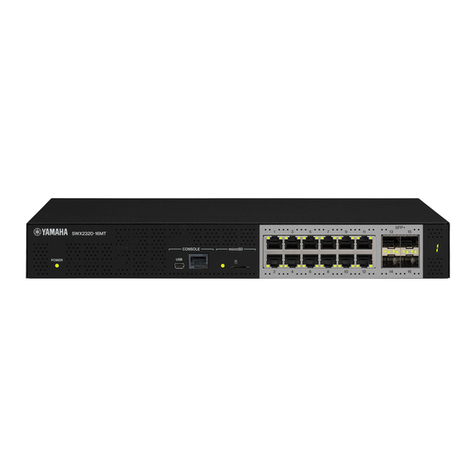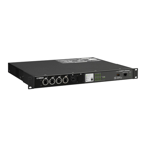
Thank you very much for purchasing the Yamaha SWX2200-8G/SWX2200-24G.
Please carefully read this manual before use to ensure appropriate installation and conguration.
Ensure appropriate and safe use of the product through first thoroughly reading and understanding the
precautionary advice provided in this document.
Please retain this manual in a safe place for future reference.
Please ensure you have all the following accessories
• Power Cable (1)
• Power Cable Clamp (1)
• Metal Fittings & Screws for Rack Mount (2 Metal Fittings, 8 Screws) (SWX2200-24G only)
• Instruction Manual (this document)
Particular usage in this manual
Abbreviations
The following will be used to refer to the product and their parts in this document;
• Yamaha Smart L2 Switch, SWX2200-8G/SWX2200-24G: This product
• Microsoft® Windows®:Windows
• 10BASE-T/100BASE-TX/1000BASE-T Cable: LAN Cable
Concerning trademarks
• “Ethernet” is a registered trademark of Fuji Xerox Company.
• “Microsoft” and “Windows” are registered trademarks of U.S. Microsoft in United States of America and other
countries.
• This document provides information on using the basic functions of the product. More detailed information is available from Help on
the Setting Screen and the following website, (http://www.yamaha.com/products/en/network/). Please ensure to refer to it as necessary.
• No part of this document may be copied or used in any form without prior permission from Yamaha.
• The content of this document and the specications of the actual device and Setting Screen are subject to change without prior notice
for the sake of improvement.
• Our company cannot accept any responsibility for any damages such as the loss of any information that occurs as a result of using the
product. Please note that the guarantee is limited to the range of physical damage to the product itself.
Important notice
Caution when Transferring/Disposing of the Product
Ensure to initialize the settings before transferring/disposing of the product.
Refer to the Web site (http://www.yamaha.com/products/en/network/) for more details.
SWX2200-8G/
SWX2200-24G
Instruction Manual
Smart L2 Switch
Safety precautions
Please ensure to carefully read and observe the following precautions in thereby ensuring safe use of the product.
The cautionary advice provided in this document concerns the appropriate and safe use of the product and the
prevention of any risk to customers and other people, or damage to any assets.
Please ensure to retain it somewhere anyone using the product can access at any time after having rst thoroughly
read it.
1. This product is intended for use in general ofces and was not designed for use in any elds requiring a high
degree of reliability in the handling of human lives or valuable assets.
2. Please note that Yamaha cannot accept any liability for any losses or damages resulting from improper use.
3. Please ensure to only use the included dedicated power cable. Failure to observe this could result in re,
electric shock, or damage to the product.
4. Ensure to immediately remove the power cable from the outlet in case of any of the following. Failure to
observe this could result in re or an electric shock. Ensure to request your agent to carry out any necessary
repairs and inspections.
• Any abnormal odor or noise occurs;
• Smoke is emitted;
• The product is broken; or
• The product has been exposed to water.
5. Ensure not to handle the product and power cable with wet hands. Failure to observe this could result in
electric shock or damage to the product.
6. Do not insert any metal, paper, or foreign objects into any of the gaps in the panel. Failure to observe this
could result in re, electric shock, or damage to the product.
7. Do not disassemble or alter this product in any way. Failure to observe this could result in re, electric
shock, or damage to the product.
8. Ensure not to damage the cable. Failure to observe this could result in re, electric shock, or damage to the
product.
• Ensure not to place any heavy objects on the cable.
• Ensure not to process the cable in any way.
• Ensure not use any staples to x the cable in place.
• Ensure not to apply excessive force to the cable.
• Ensure to keep the cable away from anything hot.
9. Please ensure to only use a power source voltage within the following range: AC 100 – 240V (50/ 60Hz).
Use of the product with a different voltage supply, such as that used overseas, could result in re, electric
shock, and damage to the product.
10. Connect the power plug to an outlet that you can see and reach in thereby ensuring that you can easily
remove it if the necessity arises.
11. Ensure to fully and securely insert the power plug into the outlet. Being insufciently inserted could result in
an electric shock. It could also lead to dust accumulating on the plug, which could then result in heat or re.
12. Verify that the current capacity of the outlet or a power strip in thereby ensuring that use of the product does
not exceed it. Any overheating or degradation of the power strip could result in re.
13. Ensure to only use cables that suit the specications of the port concerned. Connecting any cable other than
which ts the originally intended specications could result in re or damage to the product.
14. Ensure not to touch any of the ports with your ngers or anything metallic. Failure to observe this could
result in electric shock or damage to the product.
15. Ensure the product does not fall or strongly impacted. The internal parts could break, which could then result
in electric shock, re, or damage to the product.
16. Ensure not to install the product anywhere dusty/humid, or where it will be exposed to oily smoke/steam,
corrosive gas, or a strong magnetic field. Failure to observe this could result in fire, electric shock, or
damage to the product.
17. Ensure adequate heat ventilation. Failure to observe this could result in re or damage to the product.
• Ensure not to cover the product with a cloth or tablecloth.
• Ensure the product does not get pushed into a narrow, poorly ventilated place.
• Ensure the ventilation holes and fan do not get blocked.
18. The SWX2200-24G utilizes a fan to cool the inside of the equipment down. Ensure to periodically conrm
that the fan is operating normally. If the fan does fail then it will not cool the equipment down enough and
could result in re or damage to the equipment. Ensure to immediately turn off the equipment if the fan does
fail.
19. Ensure not to touch the product or the power cable if you hear any thunder. Failure to observe this could
result in electric shock.
20. Periodically remove any dirt and dust from the power cable. Failure to observe this could result in re.
21. Ensure not to install the product anywhere unstable or where it will be exposed to vibrations as it could fall
over or turn upside down, thus resulting in injury or damage to the product.
22. Ensure not to install the product anywhere it will be exposed to direct sunlight or extraordinarily high
temperatures (near a heater, etc.). Failure to observe this could result in damage to the product.
23. Ensure not to use the product anywhere it will be exposed to rapid changes in the ambient temperature. Any
rapid change in the ambient temperature could result in condensation on the product, which could then result
in damage to the product. Ensure to leave the product for a while until it has dried off with the power turned
off if any condensation has occurred.
24. Ensure not to stack the product with other equipment. Failure to observe this could result in heat building up
and damage to the product.
25. Ensure not to connect any cables while the power is turned on. Failure to observe this could result in damage
to the product and any connected equipment.
26. Ensure to earth any static electricity from your body or clothing before touching the product. Failure to
observe this could result in damage to the product.
27. Ensure not to connect any noise generating devices on the same power line as the product. Failure to observe
this could result in a malfunction or damage to the product.
28. Use of the product can result in noise being generated in telephones, radios, and TVs. If any noise does
occur then please change the place or direction in which the product is installed.
29. Ensure all the communication cables are kept apart from the power cable, etc. Failure to observe this could
result in a large amount of voltage being generated and a subsequent malfunction.
30. Please ensure to remove the power plug from the outlet when not using the product.
31. Ensure to follow the instructions of your local government when disposing of the product.
32. A 1000BASE-T connection will require an Enhanced Category 5 (CAT5e) or better LAN cable.
Major specifications
SWX2200-8G
External Dimensions (width x height (legs included) x depth (protrusions excluded)):
220mm x 44mm x 118mm
Weight:
Main Body: 950g (accessories excluded)
Power Supply:
AC100-240V (50/60Hz), 0.13A (max)
Power consumption:
Max. 7 W
Operating environment:
Ambient temperature: 0 ~ 50 ºC
Ambient humidity: 15 ~ 80% (no condensation)
Storage environment:
Ambient temperature: -20 ~ 50 ºC
Ambient humidity: 10 ~ 90% (no condensation)
Regulatory Compliance:
Safety: IEC 60950-1, EN 60950-1
EMC: EN 55022 Class A, EN 55024, VCCI Class A
LAN interface:
Ethernet (RJ-45) 10BASE-T/100BASE-TX/1000BASE-T
Straight/Cross auto-distinction
Indication function (LED)
Front panel: POWER, MODE,(LINK/ACT, SPEED, DUPLEX, STATUS) x 8
LINK/ACT, SPEED, DUPLEX, and STATUS can be switched through using the Mode Button.
Accessories:
Power Cable (1), Power Cable Clamp (1), Instruction Manual (this document)
SWX2200-24G
External Dimensions (width x height (legs included) x depth (protrusions excluded)):
445mm x 44mm x 200mm
Weight:
Main Body: 2.7kg (accessories excluded)
Power Supply:
AC100-240V (50/60Hz), 0.27A (max)
Power consumption:
Max. 27 W
Operating environment:
Ambient temperature: 0 ~ 40 ºC
Ambient humidity: 15 ~ 80% (no condensation)
Storage environment:
Ambient temperature: -20 ~ 50 ºC
Ambient humidity: 10 ~ 90% (no condensation)
Regulatory Compliance:
Safety: IEC 60950-1, EN 60950-1
EMC: EN 55022 Class A, EN 55024, VCCI Class A
LAN interface:
Ethernet (RJ-45) 10BASE-T/100BASE-TX/1000BASE-T
Straight/Cross auto-distinction
Indication function (LED)
Front panel: POWER, MODE,(LINK/ACT, SPEED, DUPLEX, STATUS) x 24
LINK/ACT, SPEED, DUPLEX, and STATUS can be switched through using the Mode Button.
Accessories:
Power Cable (1), Power Cable Clamp (1), Metal Fittings & Screws for Rack Mount (2 Metal Fittings, 8
Screws), Instruction Manual (this document)
ZQ64340 The product utilizes the Net-SNMP library, which is open source software.
Net-SNMP License Article
Copyright 1988, 1989, 1991, 1992 by Carnegie Mellon University All Rights Reserved
Permission to use, copy, modify, and distribute this software and its documentation for any purpose and
without fee is hereby granted, provided that the above copyright notice appear in all copies and that both
that copyright notice and this permission notice appear in supporting documentation, and that the name
of CMU not be used in advertising or publicity pertaining to distribution of the software without specic,
written prior permission.
CMU DISCLAIMS ALL WARRANTIES WITH REGARD TO THIS SOFTWARE, INCLUDING
ALL IMPLIED WARRANTIES OF MERCHANTABILITY AND FITNESS, IN NO EVENT SHALL
CMU BE LIABLE FOR ANY SPECIAL, INDIRECT OR CONSEQUENTIAL DAMAGES OR ANY
DAMAGES WHATSOEVER RESULTING FROM LOSS OF USE, DATA OR PROFITS, WHETHER IN
AN ACTION OF CONTRACT, NEGLIGENCE OR OTHER TORTIOUS ACTION, ARISING OUT OF
OR IN CONNECTION WITH THE USE OR PERFORMANCE OF THIS SOFTWARE.
