manuals.online logo
Brands
  1. Home
  2. •
  3. Brands
  4. •
  5. Yamaha
  6. •
  7. Synthesizer
  8. •
  9. Yamaha DX11 User manual

Yamaha DX11 User manual

YAMAHA
DIGITAL PROGRAMMABLE ALGORITHM SYNTHESIZER
SYNTHETISEUR PROGRAMMABLE FMNUMERIQUE AALGORITHMES
DIGITALER PROGRAMMIERBARER ALGORITHMUS SYNTHESIZER
SINTETIZADOR DIGITAL ALGORITMICO PROGRAMABLE
»<ii
POPERATING MANUAL
MANUEL D'UTILISATION
BEDIENUNGSANLEITUNG
MANUAL DE INSTRUCCIONES
TSg]^
YAMAHA II 3-^-^ 1 1 ^^:^~^W
II
INTRODUCTION
Thank you for purchasing the Yamaha DX11 FM Digital Programmable Algorithm
Synthesizer. The DX11 is an 8-note polyphonic keyboard that can act as up to 8in-
dependent instruments. Some of the many features of the DX11 are...
61 -note velocity and pressure sensitive keyboard.
128 preset and 32 user-programmable voice memories.
32 user-programmable performance memories.
Data is compatible with the TX81Z tone generator and
the DX2V27/27S/100 synthesizers.
Data can be stored on aRAM cartridge or cassette tape.
FM synthesis using non-sJnewave waveforms.
Two independent LFOs and eight vibrato generators.
13 Microtonal Scales (2 user-programmable and 11 preset).
•Pan, Chord and Delay effects.
•Alternate Voice Assign lets you play adifferent voice with
each successive note.
•Quick Edit functions.
•Illuminated LCD for good visibility.
In order to take full advantage of the DXII's functions, please
read this manual carefully.
TABLE OF CONTENTS
Front/Rear Panel 2
Introducing the DXII 4
Single Play 6
Single Edit 7
Performance Play 14
Performance Edit 16
Utility 18
Other Functions 24
Ideas and Suggestions 24
Waveform Harmonic Content 25
Error Messages 26
DX/TX Data Compatibility 28
What's FM? 28
Performance Memo Chart 30
Voice Memo Chart 31
MIDI Implementation Chart 32
Index 33
PRECAUTIONS
•Avoid placing the DX11 in direct sunlight or close to
asource of heat. Also, avoid locations where the unit
is likely to be subjected to vibration, excessive dust,
cold or moisture.
•Avoid rough handling, such as applying excessive force
to the switches or dropping the unit. While the internal
circuitry is of reliable integrated circuit design, the unit
should be treated with care.
•Always grip the plug directly when removing it from
an AC outlet. Removing the plug from the AC outlet
by pulling the cord can result in damage to the cord
and possibly ashort circuit. It is also agood idea to
disconnect the DX11 from the AC outlet if you don't
plan to use it for an extended period of time.
•If necessary, clean the DX1 1using aslightly damp
fcloth, and dry with asoft cloth. Never use solvents
{such as benzine or thinner) since they can melt or
discolor the finish.
All computer circuitry, including that in the DX11, is
sensitive to voltage spikes. For this reason, the unit
should be turned off and unplugged from the AC outlet
in the event of an electrical storm. This precaution
will avoid the chance that ahigh voltage spike caused
by lightning will damage the unit.
Computer circuitry is also sensitive to electromagnetic
radiation. Becareful notto set ittoo closeto equipment
{such as atelevision set) that generates electromag-
netic fields. Proximity to such equipment could cause
malfunctions in the DXl 1's digital circuitry and in-
terfere with the operation of the other unit.
When inserting acartridge, make sure it is facing the
correct way, and do not use excessive force.
This unit contains no user servicable parts. Opening
it or tampering with it can lead to electrical shock as
well as damage, and will void the product warranty.
Refer all servicing to qualified Yamaha personnel.
SPECIFICATIONS
•Keyboard
61 keys CI C6, velocity and pressure sensitive
•Tone Generator
FM tone generator: 4operator (8 wave) x8voice
•Polyphony
lip 8notes
•Memory
128 ROM voice, 32 RAM voice, 32 RAM per-
formance
•Controls
PITCH, MODULATION, VOLUME, DATA ENTRY
•Display
LCD {16 characters x2lines, illuminated)
•Terminals
BREATH, PHONES, OUTPUT {I/MIX, II), VOL-
UME PEDAL, FOOT CONTROLLER, FOOT
SWITCH, MIDI (IN, OUT, THRU), CASSETTE
•Dimensions (W xHxD)
901 X298 x63 mm (35 1/2 x113/4 x21/2")
•Weight
7.0 kg (15 lbs 6ozs)
•Power Requirements
U.S. &Canadian models: 120V, 50/60 Hz
General models: 220-240V, 50Hz
•Power Consumption
10 W
•Included Items
Cassette cable
@®®® ®®®«
FRONT/REAR PANEL
FRONT PANEL
(T) BREATH CONTROLLER JACK: Abreath controller (BC
1
or BC2) connected to this jack can control the Pitch
Modulation, Amplitude Modulation, Pitch Bias or
EG Bias of" avoice, for the expressive phrasing typical
of awind instrument.
(2) PITCH WHEEL: This bends the pitch up or down. The
range of the effect will depend on the Pitch Bend
settings for each voice.
(3) MODULATION WHEEL: This controls modulation effects
(vibrato, tremolo and"wah"). The actual effect de-
pends on the Modulation Wheel settings for each
voice.
(J) VOLUME: In Single mode, this controls the overall vol-
ume.
In Performance mode, it controls the voices played
by the built-in keyboard.
(D CARTRIDGE SLOT: ARAM cartridge such as the RAM4
can store DX-1 1data.
(6) CURSOR: These keys move the blinking cursor in the
LCD.
(7) DATA ENTRY SLIDER and -iy +1: These are used to
change the data shown in the LCD. The -1/+ 1keys
adjust data values down/up in steps of one, and are
also used to answer "no/yes" to prompts in the LCD.
(8) STORE: Voices or performances can be stored in DX-1
1
internal memory or in aRAM cartridge. In Single
Edit mode, this key is used to copy an Envelope setting
from operator to operator. In Utihty mode, this key
is used to copy an Effect setting to another effect
memorv.
®®
:.^ '^'\? l:V. ,!^ ;^^ .
f^^^^s ^
gg ^?g^ ^-
?^' ^-^^^ ^
aaaaOipaa
(odBdi'd) o£p CTC^Q.CT CT &QOO
UJ
Z
I
O
(9) LCD: A16-character two-line Liquid Crystal Display,
illuminated for visibility,
(f^ INTERNAL: Select internal memories.
(jj) BANK A—D: These keys select preset voice banks A—D.
In Single Edit mode they turn operators on/off.
(J|) CARTRIDGE: Select memories from adata cartridge.
@SELECT 1—32: In Single Play mode these keys select
voices. In Performance Play mode they select per-
formances. In other modes they select the functions
printed above and below the keys.
KEYBOARD: A61 -note keyboard, with Velocity and After-
touch sensitivity.
UTILITY: Utility mode has useful functions relating to MIDI,
data storage, effects, micro tuning, etc.
M.PROTECT: Before data can be stored in DX-1 1internal
memory or in aRAM cartridge. Memory Protect must
be off.
EDIT: Edit mode is where you modify or create your own
voices or performances. While in Edit mode, you can
press this key again to Compare the edited data with the
original data.
SINGLE: In Single mode the DX-11 can play chords of up
to 8notes with asingle voice.
PERFORMANCE: In Performance mode the DX-11 can act
as up to 8independent instruments.
(p ®(3) ®S)®® ®(9)
YAMAHA
REAR PANEL
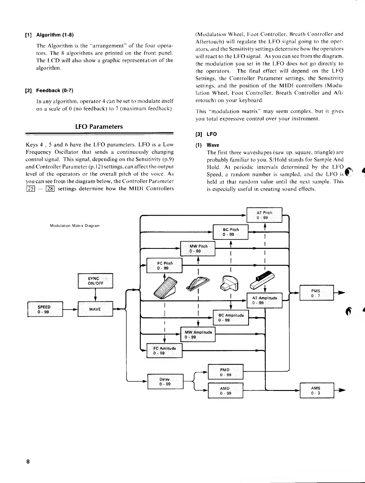
(T) CASSETTE: Use the included cassette cable to connect
adata cassette recorder for saving and loading DXl 1
data.
(D MIDI THRU: All messages received at MIDI IN are re-
transmitted unchanged iVom this terminal.
@MIDI OUT: DX 11bulk data can be sent from this terminal
to another DX 11 or to abulk data storage device such
as the MDF MIDI Data Recorder.
(4) MIDI IN: MIDI messages coming into this terminal can
control the DXl 1, and DXl 1bulk data can also be
received here.
®FS: Afoot switch such as the FC4 or FC5 connected to
this jack can control Sustain or Portamento.
®FC: Afoot control pedal such as the FC7 or FC9 con-
nected to this jack can control Volume, Pitch Mod-
ulation or Amplitude Modulation.
®VOLUME: Afoot control pedal such as the FC7 or FC9
connected to this jack can control volume in the same
way as the front panel volume slider.
®OUTPUT l/ll: Sound produced by the DXl 1is sent from
here to an external mixer or amp. Each instrument
in aPerformance can be assigned to either or bott^^x,
outputs. If only output Iis plugged in, it will transmit"-'
the combined signal for both outputs.
®PHONES: Ajack for standard stereo or mono head-
phones. Using this jack will not affect the rear panel
outputs.
INTRODUCING THE DX11
There are two ways to play the DXl 1: SINGLE mode and
PERFORMANCE mode. In Single mode, you can play a
single voice (sound) using chords of up to 8notes, In Per-
formance mode, the 8tone generators (sound-producing
circuits) can act independently as up to 8different instru-
ments, each assigned to its own section of the keyboard or
producing sound in response to incoming MIDI signals.
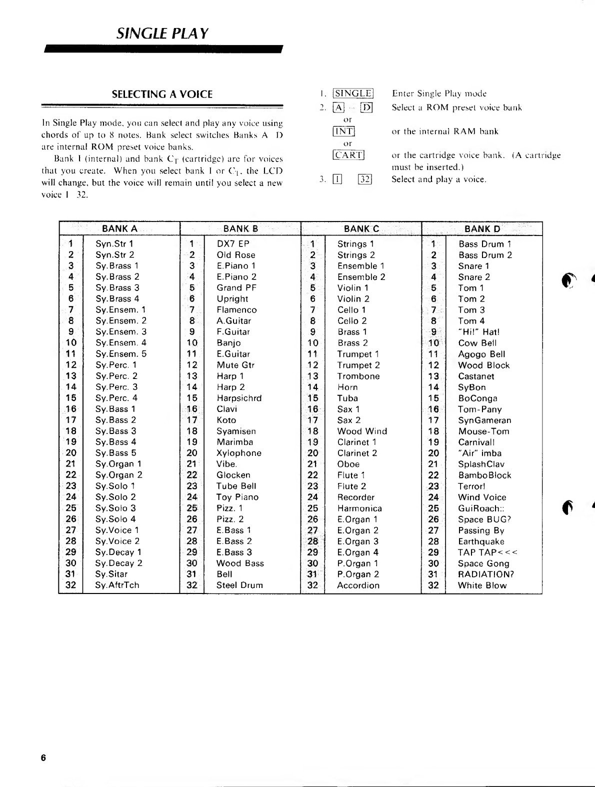
SINGLE PLAY: Select and play any voice using chords of up
to 8notes.
SINGLE EDIT: Create your own voices or modify an existing
voice.
PERFORMANCE PLAY: The DX 11acts as up to 8independent
instruments as specified in the Performance Memory
you select. Each instrument can play adifferent voice
over adifferent section of the keyboard, and can be
controlled independently.
PERFORMANCE EDIT: Change the settings of aPerformance
Memory.
UTILITY: Various useful functions for data storage, micro
tuning, effects, etc.
MEMORY
Here are the main types of memory in the DXl 1.
Voice Memory: There are 5voice memory banks, each with
32 voices. Banks A-D are preset, and cannot be changed.
Bank I(internal) is for you to store your own voices in.#^
(For details please see p. 6)
BANKS ABCD1
voices 1-32 132 1-32 132 1-32
Performance Memory: Each performance memory can set
the DXl 1to act as up to 8independent instruments,
each on its own area of the keyboard.
_i_^^^_J__A_±:j^^-t-i:|.7 ^g
}isMi^Ljssij!m^
.fttB^Ch(1-,i<l,<»>if>,i)
Jjffi'U.ti..„,J£igr.fl.81-,
SmM>!<...tM.:z....mi..
OutAasWp VoW.l.lt.HI)
.lf^„s»,tea
Effect Memory: Each performance can use one of three types
of effects; Delay, Pan or Chord. (There are four memories
for each of the three effects.)
CONNECTIONS
^
Effect 1(Delay)
Oelay Tirm
Pitch Shift
Feedback
EffKit Level
Effect 2(Pan)
Select
Direction
Part Range
Etteci3 (Chord)
Chofd note I
ilIM?P*F
Connect the audio output of the DXl 1to an amp/speaker
system, or plug in aset of headphones. When you turn the
power on, the DXIl will display "**** YAMAHA
**** <How are you? >"for afew seconds (this greeting
can be changed, see p. 24), and then will display whatever
function was selected when the power was turned off.
US
O
z.
o
3
a
Q
tr
H
z
Program Change Table: Incoming program change messages
can select voice or performance memories.
Program Change Table
Incoming Elected
1B19
PF?42
3107
127
128
A32
C14
Micro Tune: You can use scales other than the standard "equal
jj^ temperament" found on pianos and organs. POl—PU
~are preset, Octave and Full are programmable.
1/8 Tone
V4Tone
User Full
C-2 —
-
C#-2
-1- '
1: .
..';
.
.»
t
r; .
.. (;
.t' '
.
G8
PI WVattattt &Voung
/
POl Pure (maior)
Equal
UserOctawe
C3
C#3
1D
!D#
!E
IF/
Jm/
IG/
1G#
iA
!A#
B3
SINGLE PLAY
SELECTING AVOICE
In Single Play mode, you can select and play any voice using
chords of up to 8notes. Bank select switches Banks AD
are internal ROM preset voice banks.
Bank 1(internal) and bank Cj (cartridge) are for voices
that you create. When you select bank Ior C-[, the LCD
will change, but the voice will remain until you select anew
voice 132.
ISINGLEl Enter Single Play mode
Select aROM preset voice bank
or the internal RAM bank
2. [A] [D]
or
llNTl
or
[cart] or the cartridge voice bank. (A cartridge
must be inserted.)
3. Q] |32i Select and play avoice.
BANK ABANKB BANKt BANKD
1Syn.Str 1iDX7 EP 1Strings 11Bass Drum 1
2Syn.Str 22Old Rose 2Strings 22Bass Drum 2
3Sy. Brass 13E. Piano 13Ensemble 13Snare 1
4Sy. Brass 24E. Piano 24Ensemble 24Snare 2
5Sy. Brass 35Grand PR 5Violin 15Tom 1
6Sy. Brass 4 6 Upright 6Violin 26Tom 2
7Sy.Ensenn. 1-r\' Flamenco 7Cello 17Tom 3
BSy.Ensem. 28A. Guitar 8Cello 28Tom 4
9Sy.Ensem. 39F. Guitar 9Brass 19"HI!" Hat!
10 Sy.Ensenn. 410 Banjo 10 Brass 210 Cow Bell
11 Sy.Ensem. 511 E. Guitar 11 Trumpet 111 Agogo Bell
12 Sy.Perc. 112 Mute Gtr 12 Trumpet 212 Wood Block
13 Sy.Perc, 213 Harp1 13 Trombone 13 Castanet
14 Sy.Perc. 314 Harp 2 14 Horn 14 SyBon
15 Sy.Perc. 415 Harpsichrd 15 Tuba 15 BoConga
16 Sy.Bass 116 Clavi 16 Sax 116 Tom-Pany
17 Sy.Bass 217 Koto 17 Sax 217 SynGameran
18 Sy.Bass 318 Syamisen 18 Wood Wind 18 Mouse-Tom
19 Sy.Bass 419 Marimba 19 Clarinet 119 Carnival 1
20 Sy.Bass 520 Xylophone 20 Clarinet 220 "Air" imba
21 Sy.Organ 121 Vibe. 21 Oboe 21 SplashClav
22 Sy.Organ 2M.' Glocken 22 Flute 122 BamboBlock
23 Sy.Solo 123 Tube Bell 23 Flute 223 Terror!
24 Sy.Solo 224 Toy Piano 24 Recorder 24 Wind Voice
25 Sy.Solo 325 Pizz. 125 Harmonica 25 GuiRoach::
26 Sy.Solo 426 PIzz. 226 E. Organ 126 Space BUG?
27 Sy.Voice 127 E.Bass 127 E. Organ 227 Passing By
28 Sy.VoJce 228 E.Bass 228 E. Organ 328 Earthquake
29 Sy. Decay 129 E.Bass 329 E. Organ 429 TAP TAP<<<
30 Sy. Decay 230 Wood Bass 30 P. Organ 130 Space Gong
31 Sy.Sitar 31 Bell 31 P. Organ 231 iRADIATION?
32 Sy.AftrTch 32 Steel Drum 32 Accordion 32 White Blow
SINGLE EDIT
STORING AVOICE
You can store the currently selected voice (edited or not) in
bank 1(internal). While in SINGLE PLAY mode, hold down
the STORE switch and press a switch 132 to select the
destination memory. To store avoice to bank Ci(cartridge),
press CARTRIDGE, then hold down STORE and select the
destination I32.
MEMORY PROTECT
%
When Memory Protect is On, you will not be able to store
voices or performances, nor will the DXl 1be able to receive
incoming MIDI bulk data. Press M. PROTECT, move the
blinking cursor and use the OFF/ON switches to turn the
Internal and Cartridge protect off/on. Memory Protect is reset
to On when the power is turned on.
This is where you create your own voices or edit the preset
voices. We will assume that you know something about FM
synthesis, If you are new to FM, please turn to page 28 and
read "What's FM?" before continuing.
The DXl 1has some "Quick Edit" parameters that you can
use to easily change the overall character of the sound. See
page 13.
THE EDIT BUFFER
When you select avoice, the data is read into aplace called
the "Edit Buffer," and this data tells the DXl 1how to make
sound. Changes you make in Edit mode will affect only the
data in this buffer, and are not permanent until you Store.
(See above on how to Store.)
EDIT/COMPARE
When you first enter Single Edit mode, the LCD will show
an "E" in the upper left corner, indicating "Edit", As soon
as you modify the data, this will change to "e". Once you
have modified the data, you can compare the results of your
editing with the original voice. Press EDIT/COMPARE. The
LCD will show a"c" in the upper left corner, indicating
"Compare". You can select the various parameters to see the
original data, but will not be able to modify the settings. To
return to Edit mode, press EDIT/COMPARE once more.
You cannot leave Compare mode before returning to Edit.
55
^
Original data
I
Modified
i
Compare original data
i
:: L11 1Ai,c 1-1111 Ai,(;i
"(;(:dbcick(0P4) cU 11A[,(^l
rc'efiback (OP 4)=6
PARAMETERS
A"parameter" is something you can change to affect the
sound. Press the 130 and 32 switches to select the parameters
printed above them. (Some switches have several
parameters—press the key repeatedly to access them.) Use
the ^>switches to move the blinking cursor, and use the
Data Entry slider or -1/ +1switches to change the data.
OPERATOR ON/OFF
When editing, it is often useful to hear only certain operators
by themselves. In Single Edit mode you can use the bank select
keys A- Dto turn operators 1--4 off or on. (This will be
indicated in upper left of the LCD, For example, "1 101"
indicates that operator 3is off.) Obviously, if all carriers
are turned off, there will be no sound.
[1] A[gorithm(1-8)
The Algorithm is the ''arrangement" of the four opera-
tors. The 8algorithms are printed on the front panel.
The LCD will also show agraphic representation of the
algorithm.
[2] Feedback (0-7)
In any algorithm, operator 4can be set to modulate itself
on ascale of (no feedback) to 7(maximum feedback).
LFO Parameters
Keys 4,5and 6have the LFO parameters. LFO is aLow
Frequency Oscillator that sends acontinuously changing
control signal. This signal, depending on the Sensitivity (p.9)
and Controller Parameter (p. 12) settings, can affect the output
level of the operators or the overall pitch of the voice. As
you can see froiji the diagram below, the Controller Parameter
[25] —[28] settings determine how the MIDI Controllers
(Modulation Wheel, Foot Controller, Breath Controller and
Aftertouch) will regulate the LFO signal going to the oper-
ators, and the Sensitivity settings determine how the operators
will react to the LFO signal. As you can see from the diagram,
the modulation you set in the LFO does not go directly to
the operators. The final effect will depend on the LFO
Settings, the Controller Parameter settings, the Sensitivity
settings, and the position of the MIDI controllers (Modu-
lation Wheel, Foot Controller. Breath Controller and Aft-
ertouch) on your keyboard.
This "modulation matrix" may seem complex, but it gives
you total expressive control over your instrument.
[3] LFO
(1) Wave
The first three waveshapes (saw up, square, triangle) are
probably familiar to you. S/Hold stands for Sample And
Hold. At periodic intervals determined by the LFO
Speed, arandom number is sampled, and the LFO is
held at that random value until the next sample. This
is especially useful in creating sound effects.
^-.AT-Pitch;;
1
^M'y..:-.
-
t
Modulation Matrix Diagram BC Pitch
0-99 1
MW Pitch
0-99 t.'
*-
11
k
FC Pitch
-:;:0;-;99;..-; .;.
^'.'
-
SYNC ?;
ON/OFF ^:phAs
.Q7.
1'
^.^^^t 'Sn.-^-viJP ^r
'-AT Amplitude
0-99
5PEED
.;-6>:S9-'.-: WAVE
L
1
1
111
*s
I8C Amjplitgde
1
1.f
i
MWAmptilude
0-89
1^
1r"PMD
0-99
:.; Delay :^^
:0-99
^^ »- —
<
JI.^AMD :AMS
0*3
0-99
f
saw up
(saw tooth wave) ^---^
squ^e
(square wave)
1
1
triangle
(triangle wave) ^-x^
S/Hold
(sample &hold) nT^flArUi
(2) Speed (0-99)
At asetting of 35, the LFO will make 6.7 cycles every
second, and at 99, 55 cycles every second.
(3) Delay (0-99)
fIn many acoustic instruments, the vibrato begms ashort
time after the note begins sounding. This can be simulated
using the LFO Delay, which is adjustable from (no
delay) to 99 (about 10 seconds).
(4) Sync (off/on)
When Sync is on, each note will reset the LFO wave to
its beginning. For example, the Saw Up wave would begin
again from the lowest position at the beginning of the
note. When sync is off, the LFO wave will keep repeating
regularly, regardless of notes being played.
continues fcgaidless of key on
(changes continuously.)
AA
Key Key
[5] Sensitivity
This is where you set the sensitivity of the voice to LFO
Pitch Modulation, and set the sensitivity of each operator
to incoming LFO and other control signals.
(1) PMod Sens. (0-7)
This determines the Pitch Modulation Sensitivity (0—7)
of the entire voice. If it is 0, there will be no pitch mo-
dulation (vibrato).
(2) AMS (0—3, on/off for each operator)
The overall AmpHtude Modulation Sensitivity of the
operators is adjustable from 0—3, and each operator can
be set to react to LFO Amplitude Modulation (on) or
not (off). For example, if the carrier operators were
sensitive to LFO amplitude modulation, the LFO would
affect the volume of the voice (tremolo). If the modulator
operators were sensitive to LFO amplitude modulation,
the LFO would affect the tone of the voice (wah-wah).
(3) EBS (0 7for each operator)
This sets the EG (envelope generator) Bias Sensitivity
of each operator. EG Bias is acontrol signal that directly
affects the output level of an operator. (It has nothing
to do with the LFO.) The EG Bias you set here can
be controlled from aBreath Controller or with After-
touch.
If acarrier has EBS, the EG Bias signal will affect
the volume of the voice. If amodulator has EBS. the
EG Bias signal will affect the tone o^ the voice. When
programming wind instruments, it is effective to set the
carriers to an EBS of 7and set BC EG Bias to 99 so that
the volume will depend totally on how hard you blow
into the Breath Controller (see p. 13). Set the modulators
to alower value of sensitivity, so that the tone will become
somewhat sharper as you blow harder. Setting EG Bias
Sensitivity 17will automatically lower the output of
the operator by 0- 96dB in order to give it "somewhere
to go" when an EG Bias signal comes in from the Breath
Controller or from Aftertouch.
[4] LFO Depth
(1) Pitch Modulation Depth (0—99)
This controls the amount of Pitch Modulation that will
be present regardless of the Function Settings. When this
value is abtive 0, the LFO will always produce some Pitch
Modulation, regardless c>^ the position of the Foot
Controller, Modulation Wheel, Breath C^ontroller. or
Aftertouch.
(2) Amplitude Modulation Depth (0—99)
This controls the amount of Amplitude Modulation that
will be sent to each operator regardless of the Function
settings. When this value is above 0, the LFO will always
send some Amplitude Modulation, regardless of the
position of the Foot Controller, Modulation Wheel,
Breath Controller, or Aftertouch.
[6] KVS {0-7 for each operator)
This sets the Key Velocity Sensitivity of each operator.
Each MIDI Note On message has aVelocity byte that
tells how hard the key was struck. If an operator has
KVS, it will adjust its output level according to the ve-
locity of the note. If acarrier has KVS, strongly played
notes will be louder, if amodulator has KVS, strongly
played notes will have asharper tone. Extremely high
KVS settings will make the voice difficult to control,
and you will need to play quite strongly to get any sound
at all. Setting KVS 1-7 will automatically lower the
output of the operator by 7-16dB in order to give it
"somewhere to go" when you play strongly.
OSCILLATOR
This is where you set the frequency of each operator. Each
operator can be set to Ratio or Fixed mode. In Ratio mode.
the frequency will depend on the key you play (ie. the
"normal" way). In I-'ixed mode, the frequency will be the
same no matter which key you play. This can be useful for
special effects, or for creating 'ibrmants" (fixed character-
istics of spectral emphasis found in human voices and some
instruments). While making Coarse [8] or Fine [9] frequency
settings, move the cursor to (xxx) and use 1,M 1to switch
between Fix and Ratio modes.
[7] Fix Range
This is where you set the frequency range of an oscillator
set to Fixed mode (see below). Repeatedly press 7to
make settings for each operator. A"*" indicates that
the operator is set to Ratio mode.
This parameter is effective only when the oscillator
mode is set to "Fixed". Think of it as being an "extra
coarse" adjustment of aFixed Frequency,
Setect(Hz) Fix Range (Hz) One Ftrve St0]? (Hz)
255 8-255 1
510 16-510 2
1K 32-1020 4
2IC 64-2040 8
4K 128-4080 16
8K 256-8160 32
16K 512-16320 64
32K 1024-32640 128
Due to hardware limitations, the very highest frequencies
will not actually be output.
[8] [9] Frequency Coarse/Fine
Repeatedly press 8or 9to set Frequency Coarse or
Fine for each operator 1-4. The "standard" ratio is
1.00; when an operator set to 1.00 frequency ratio it
will produce a440H/ tone for an A3 note (standard
pitch). Aratio of 2.00 would be an octave higher, and
4.00 would be two octaves higher.
[10] Oscillator Wave (W1—W8)
The DXl 1can perform FM synthesis using non-sinewave
waveforms. Each operator can be independently set to
one of the following 8waveforms. The selected waveform
will be graphically indicated in the LCD.
eI111-, --'-^ V-- -
OSW W5 WZ W6 W7 W1 :C\y W5: 0^
W2: ^y" W6: >^ >
^j^2-
JZ^ W7: ffl—
<
W4: "^-^^^ 1\J^Q:^^ 1
These waveforms can be used as both carriers and
modulators. Sine waves {waveform I) are pure tones,
The other seven waveforms have iidditional harmonics
already in ihem. This allows for complex waveforms to
be created from fewer operators. For ideas on how to
use the various waveforms, examine the preset voices.
The harmonic content of each waveform is describedi
on p. 25, '
[11] Detune {+3)
The frequency of each operator can be moved slightly
higher or lower. By detuning two carriers in opposite
directions, you can create adetune- chorus effect. By
detuning amodulator and carrier, you can create slightly
irregular, "natural-sounding" harmonic structures. The
amount of detune will differ over the keyboard. At C?>
asetting of +3 is equivalent to ±2.6 cents.
Envelope Generator
The Envelope Generator (EG) determines how the operator
output level changes over time. The EGs in the DXll have
4rate (speed) parameters and 1level parameter. In addition,
you can "shift" the range of the entire envelope by aspecified
amount, so that there will be some operator output even when ^
anote is not being pressed.
(LEVEL)
Key On Key Off (TIME)
[12] EG Rate
Repeatedly press 12 to set the four rates.
(1) AR(0-31)
Attack Rate determines how quickly the level will rise
up to maximum level. When AR is 0, the rate is intmitely
slow (ie. it never changes), and when AR is 31,the attack
is fastest.
10
(2) D1R(0-31)
1st Decay Rate determines how quickly the level will
decay from maximum to the 1st Decay Level. Obviously,
if the 1st Decay Level is 15 (max), the 1st Decay Rate
will have no effect
(3) D2R(a-31)
2nd Decay Rate determines how quickly the level will
decay from the 1st Decay Level down to 0. If the 2nd
Decay Rate is set to 0, the sound will continue as long
as the note is held.
(4) RR{1-15|
Release Rate determines how quickly the level will decay
from the level at the time the note is released down to
0,
[13] EG Level
^Repeatedly press 13 to set the 1st Decay Level and the
•EG Shift value.
(1) D1L{0-15)
1st Decay Level is the point where the 2nd Decay Rate
begins.
(2) EGS(off, 48, 24, 12)
EG Shift sets the range of the envelope. When "oft^'
is selected, the EG will change the operator output level
over arange of to -96dB (the full range). However,
when 12, 24 or 48 is selected, the EG range is
"compressed" to the specified range. For example, if
EG Shift is 24, the EG will change the operator output
level over arange of to -24dB, and the operator output
level will be at "24dB even before the note is pressed.
EG Shift OFF (normall 24dB
OdB
Key On Key Off Key On Key Off Key- On
This can be used to limit the ECj range of amodulator
for very subtle changes in tone, or used on acarrier to
create an instantaneous attack or effects that wit! sound
even when akey is not being pressed, The EGS setting
will not affect the time the envelope takes, even though
the "distance'' of the level change may be different (i.e.,
"rates" are automatically compensated).
EGS cannot be set for operator 1, It is fixed at "off".
EG Copy
When trying to imitate an acoustic instrument sound, it is
usually agood idea to first program the carrier envelope
(volume envelope) and copy it to the modulating operators.
(You will probably need to make fine adjustments later by
ear.) Usually, as the volume oi' asound increases (or de-
creases), the tone also gets brighter (or softer), so the mo-
dulator envelopes will resemble the carrier envelopes.
To copy an envelope while in Single Edit mode, press and
hold the STORE switch. Move the blinking cursor and use
the OPERATOR ON/OFF switches to select the source and
destination operators. The envelope (AR, DIR, DIL, D2R,
RR) and scaling parameters (LS, RS) will be copied.
[14], [15] Pitch EG
The Pitch Envelope Generator lets you change the pitch
of the sound over time. 14 sets the Rate (speed) ofchange
and 15 sets the pitch Level to make apitch envelope as
shown in the diagram.
High piich
Normal pitch
Low pitch
KEY OFF
KEY ON
[16] Operator Out Level (0—99)
This sets the output level of each operator. The output
level of acarrier will affect the volume, and the output
level of amodulator will affect the tone. If you set output
levels of over 90, the output will be distorted slightly.
Sometimes this may be desirable to create athicker
sound. What the human ear interprets as loudness is
closely related to timbral complexity (tone), and raising
the level of amodulator will often increase the "loudness"
as well.
[17] Rate Scaling (0-3)
On an acoustic instrument, high notes usually have a
faster attack and decay than low notes. Rate Scaling
simulates this. When RS is 3, high notes will have a
much shorter EG. (Even when RS is 0. high notes will
be slightly shorter,)
Low Notes High Notes
Slow EG \l^
Fast EG
Q
Ul
Ul
z
CO
11
[18] Level Scaling (0-99)
High notes on an acoustic instrument tend to have aless
complex tone than low notes. You can use Level Scaling
to simulate this by decreasing the output level of amo-
dulator as you play up the keyboard. (Level Scaling
operates on acurve starting from about Ci.) When LS
is 0, the operator output level will be the same for all
notes. When LS is 99, the output level will have dropped
to by the lime you get to the top of the keyboard.
long as you continue pressing them), and in
PERLORMANCE mode, up to 5notes will
be remembered.
[21] Pitch Bend Range (0—12)
This determines the range (0 12 semitones) of the pitch
bend effect. When set to 12, the Pitch wheel will have
amaximum effect of one octave up or down. When set
to 0, the Pilch wheel will have no effect.
Low Notes High Notes
More output Less output
[19] Transpose (+24)
The voice can be transposed up or down 2octaves in
steps of asemitone. The next key you press after selecting
this parameter will be the new transpose point (within
2octaves of middle C). You may also use the Data Entry
slider to set the transpose point. The display indicates
the note that will actually be sounded when the middle
Ckey is pressed.
[20] Poly/Mono
Poly Mode: In SINGLE mode, the voice will play up to 8
notes simultaneously; and in PERFORMANCE mode,
the voice will play as many notes as permitted in the
"Max Notes" setting for that instrument (p. 16). If there
are not enough notes available, the oldest note will be
turned off to 'make room' for the newly played note.
See EG Damp, p.23)
Mono Mode: Only the most recent note you press will be
sounded. This can be desirable when playing solos. Also,
Mono Mode gives you achoice of portamento (see [22]
Portamento Mode).
AMax Notes (p. 18) setting of 1is not quite the same
as Mono mode. In Mono mode, anote played before
the previous one is released will not re-trigger the en-
velope, and the decay will continue from the previous
note. However in Poly mode, each note starts its envelope
from the beginning even if the previous note has not been
released. Thus, if you want to have only one note
sounding at atime, but want each note to re-trigger the
envelope, use Poly mode and set Max Notes to L
Note: If you play anote in Mono Mode without re-
leasing the previous note, and then release the
second note, the sound will "jump back'" to the
previous note. In SINGLE mode, up to 8of
these previous notes will be remembered (as
[22] Portamento Mode
There are two modes oi' Portamento (the ''glide" between
notes), but you have achoice only in Mono Mode. If
Poly Mode is selected, this will always be "Full Time
Portamento".
Fingered Portamento: Portamento is applied only if you press
anote before releasing the previous one. Fingered Por-
tamento cannot be switched off. If you don't want tof^
have Portamento, set the Portamento Time to (see
below).
Full Time Portamento: Portamento is applied between all
notes. This can be turned on or off by afootswitch
connected to the rear panel FS jack.
[23] Portamento Time (0—99)
This sets the speed of the "glide" effect between notes.
When Portamento Time is at 99, athree-octave glide
will take about 30 seconds. Portamento Time of 1is the
fastest glide. When Portamento Time is at 0, there will
be no ghde. If you don't want avoice to have portamento,
set the Portamento Time to 0.
[24] Foot Switch Assign
Aon/off type controller (FC4 or FC5) plugged into the
rear panel FS jack can control either Sustain On/Off j^
or Portamento On/Off for the voice.
In Performance mode, the first voice in the per-
formance memory will determine the Foot Switch as-
signment.
CONTROLLER PARAMETERS
Parameters 25—28 allow you to regulate the amount of LFO
modulation using continuous-type controllers connected (or
built into) the DXI 1.The diagram on p,8 explains how these
control LFO modulation. Each parameter can be set between
and 99. When it is set to 0, the position of the controller
will have no effect on the amount of LFO modulation.
For example, when the FC Volume setting is at 99, the
volume of the voice will be regulated completely by the Foot
Controller. Thus, when the Foot Controller pedal is at mi-
nimum position, there will be no sound, and when the FC
Volume setting is at some middle value such as 50, there will
12
be some sound even when the Foot Controller pedal is at
minimum position.
Volume: The controller will affect the overall volume of the
voice.
Pitch: The controller will affect the amount of Pitch Modu-
lation,
Amplitude: The controller will affect the amount of Amplitude
Modulation.
Pitch Bias: The controller will directly control the pitch. (This
is a"pitch-bending" effect, and has nothmg to do with
the LFO.) When BC Pitch Bias is set at (the normal
value), the controller will not affect the pitch. Settings
of +1-+50 will allow the controller to raise the pitch,
and settings of -1—~50 will allow the controller to
lower the pitch. The further away from 0, the greater
the effect.
yEG Bias: The controller will directly control the output level
of the operators. The amount of control will depend on
the EG Bias Sensitivity for each operator (see p.9).
[25] Foot Control
Acontinuous-type controller (FC7 or FC9) connected
to the rear panel FC jack can control the voice.
(1) FC Volume
(2) FC Pitch
(3) FC Amplitude
[26] IVIodulation Wheel
The front panel Modulation Wheel can control the voice.
(1) MW Pitch
(2) MW Amplitude
[27] Breath Controller
ABreath Controller (BCl or BC2) connected to the front
panel jack can control the voice.
(1) BC Pitch
(2) BC Amplitude
(3) BC Pitch Bias
(4) BC EG Bias
[28] After Touch
Pressing down on the keyboard after you play the note
can control the voice, (i.e., "Aftertouch" as opposed to
the 'Tnitial touch" or velocity.) Aftertouch is common
to the whole keyboard—the strongest pressure on any
key will apply to all notes.
(1) AT Pitch
(2) AT Amplitude
(3) AT Pitch Bias
(4) AT EG Bias
[29] Reverb Rate {off, 1-7)
This is a"pseudo-reverb" effect created by slowing the
EG release rates after acertain point. It depends on the
OPl EG. (PPI on/off or OPl output level does not
matter.) When the OP EG level descends to -18dB,
this ^'pseudo-reverb" is triggered, and the Release Rates
of all operators will be slowed down to the Reverb Rate,
producing alingering effect characteristic of reverb.
Rev. Rate Effect
off
1
7
No effect
EG -Release Rate ^1{long "reverb")
EG -Release Rate == 7{short "reverb")
Note that if the OPl EG Attack Rate is 0, the OPl EG
level will stay below the reverb threshold, and all EG
rates will be lengthened, causing the note to sound 'slow'.
Also, if the EG Release Rate is already less than the
Reverb Rate, there will be no effect. This "pseudo-re-
verb" must be programmed with the other voice pa-
rameters in mind.
[30] Voice Name (10 characters)
You can name your newly created voice (or rename a
preset voice). Use the CURSOR switches to move the
blinking cursor, and use the DATA ENTRY switches
to step through the characters shown below.
Space ["f$-'h 'i]*+,-./Q1234:> b789:
;< =>?? AHcu!; Fc, ]\ I..; Kr, y, \opqhstuvwxy/.
\—'abcd c !" gh1^kImi^, (j pt| rs-i tti vwx>z
[|1 --
[32] Quick Edit
These Quick Edit parameters let you make overall adjust-
ments in the sound. Attack and Release adjust the attack
(and Dl rate) and release rates of all operators equally.
Volume adjusts the output level of all carriers. Brilliance
adjusts the output level (and first decay rate) ol' all modula-
tors. Whenever you enter this parameter, the Quick Edit
Setting "+"will be at the middle position.
{!) Attack
(2) Release
(3) Volume
(4) Brilliance
b
o
LU
z
5)
13
PERFORMANCE PLAY
In performance mode, you can use the DXl 1as up to eight
independent instruments, and specify the maximum number
notes, note limit, MIDI reception channel, voice number,
etc. for each instrument. The DXI 1will remember 32 of these
"Performances".
Switches 1—32 will select performances. The upper line of
the LCD will show the Performance Name, and the lower
line will show the voice numbers for each instrument. (Move
the cursor to the right to see the voice numbers for instruments
58.) If the "Max Notes" setting of an instrument is 0, the
voice number will show a"*", indicating an inactive in-
strument.
Performance number and name
rrOl y.vPt^rtName
AO 4/1332/1 VA17-.
Instruments 14
PFOl MyS'or«ame
.COl/ */*/Hi 1
Instruments 5—8
Each Performance Memory (1-32) contains the following data.
Instrument 12345678
Assign Mode Normal /Alternate
Max Notes (0-8)
Voice No. (101-D32)
Receive Ch. (1 -1 6, omni)
Limit/L (C-2~G8)
Unr)tt/H (C-2-G8)
tnst Detune ^-7- +7)
Note Shift (-24- +24)
Volume (0-99)
Out Assign (off, t, II, 1If)
LFO Select (off, 1,2,vib)
Micro Tune (select) off/on off/on off/on off/on off/on off/on off/on off/on
Effect Select off/Delay/Pan/Chord 1/2/3/4
Performance name
There is ablank Performance Memory chart on p. 31 that you may copy and use as amemo for your own settings.
SELECTING APERFORMANCE
Vo select aperformance,
!. [PBRr^ Enter Performance Play mode.
2- [j] [111 Select and play aperformance setting.
Note: When the DXil is shipped, the performance me-
mories contain data which you may want to save
before storing your own performances. See pages m^ ^
19 20 for instructions on how to save the full set
of 32 performances to cassette tape or cartridge.
STORING APERFORMANCE
You can store the currently selected performance (edited or
not) in any performance memory 1---32. While in PLAY
PERFORMANCE mode, press and hold the STORE switch,
and press akey I-32 to select the destination. The current
performance will be stored into the selected memory. (Me-
mory Protect must be off. See p. 7.) To store aperformance
to cartridge, press CARTRIDGE, then hold down STORE
and select the destination i32. If the perft)rniance uses
Internal voices (bank I), they will be changed to Cartridge
voices (bank G,). Eor the reason why, see [3] Voice Number
on p. 16.
14
FACTORY-SET PERFORMANCE DATA
When the DX1 1is shipped, the performance memories contain the following data.
1. BRASS N01! A03 Sy, Brass 1doubled,
2. Tight BASS A1 6Synth bass doubled, B28 electric bass doubled.
3. Glocken Glocken with pitch shift delay effect, rising in perfect 4ths,
4. Analog Str Press down on the keyboard to move the stereo image.
5. Hit 1Key! Afour-note chord for each note, in two banks- --one using the chord effect, and the other
using note shift.
6. Power Rap Noisy drums arranged across the keyboard.
7. EP/Flute Electric piano {6-notes) and flute (2-notes), split at G3.
8. Wind Band This uses alternate assign mode. Various wind instruments alternate.
9. PROGRESSIV Horn and synth strings (octave down)
10. Syn Lead Single voice layered for solos. Uses short delay effect.
11. LyricSplit Classic guitar and oboe split at G3,
12. Church Two pipe organs layered.
13. Rotary Str Strings with pan effect.
14. Sax Solo Two types of sax, two of each layered on each key. 2-note polyphonic.
15. Floating? Pan effect. Nice for sequencer arpeggios.
16. Brastrings Brass and strings.
17. Rich Str Smooth strings.
18. Orchestra "Orchestra hit" with brass, strings and timpani. Single-note only.
19. FolkGuitar Dual acoustic guitars.
20. Synth BASS Two types of synth bass, four of each on every note. Single-note only.
21. Latin Perc Various latin percussion arranged over the keyboard.
22. Rich Horns Stacked and detuned horns.
23, Magic Slam Delay effect. Try the aftertouch.
24. Tension Chord effect, with high tension chord.
25. Honky Tonk Alternate assign to mistune alternate notes.
26. B(R)ASS Brass or Bass?
27. "Fantasy" Synth strings with white noise as you raise the modulation wheel.
28. Power Solo Short delay effect. 2-note polyphonic.
29. HeavyBrass Stacked voices for depth.
30. Blues Time C1 -F2 has normally tuned bass. White keys G2-C6 play the blues scale. Black keys above
F2 play ajazzy chord C,F,G.
31. Brass Band Trumpet and trombone.
32, I'm ZOMBI Sound effects and percussion arranged across the keyboard.
UJ
O
z
<
cc
s
cc
111
a.
TRANSMIT CHANNEL/RECEIVE CHANNEL
Each of the up to eight instruments in ti performance can
have its own Receive Channel 116. (see p. 16). Thus,
messages coming into MIDI IN on eight different channels
can control each instrument independently. In the same way,
the keyboard built into the DXll has its own Transmit
Channel (see p. 18), and in Performance mode, will control
only the instruments that have amatching Receive Channel.
See the diagram at right.
The DXII's
built-in keyboard
pill III II III II III II III
MIDI OUT Transmit channel
External keyboards
or sequencers
MIDI I
The DX1 1sbuilt-m tone
generators (separate Receive
Channel ^or each voice)
15
PERFORMANCE EDIT
In PERFORMANCE mode, press EDIT. The LCD will show
the previously edited parameter. When you first enter Edit
Performance mode, the upper left character of the LCD will
be a"P'\ but as soon as you make achange, this will change
to "p'\ indicating that the performance data has been mod-
ified, As in Single Edit mode, you can Compare the results
of your editing with the original data by pressing COMPARE.
The upper left character will change to "c" to indicate this.
You cannot leave Compare mode before returning to Edit.
Original data unchanged Modified
1i
Comparing original
i
nss ign Mode^nonn PERFORMANCE EDIT
Assign Mode=altr CERFOR>'ANCE EDIT
Assign Mode^norm
EDITING PROCEDURE
Press the 114 switches to select the parameters. Most Per-
formance Parameters have independent settings for instru-
ments 1-8. The LCD has space to show only four instruments
at once, so an arrow on the edge of the lower line indicates
that there is more data to be seen. Move the cursor to set
the data for instruments 5-8. Use the DATA ENTRY slider
and switches to change the data value at the blinking cursor.
If the Max Notes setting (see [2] Maximum Notes) of an
instrument is 0, that instrument is inactive, and its data will
be indicated by a"*'\ (You can not edit an inactive in-
strument.) In the example below, instruments 2and 3are
inactive.
IJ.liD HECiilVE CH
1/ */*/if)-.
Instruments 12 34
p. ED RECfc;iVE CH
^7/ omn /12/ =
5678
THE PERFORMANCE EDIT BUFFER
When you select aPerformance Memory, the data is loaded
into the Performance Edit Buffer, and this data tells the DX 1
1
how to behave. Changes you make in Edit mode affect this
buffer, and are not permanent until Stored into one of the
Performance Memories 132. (See Storing APerformance,
p.l4.)
[1] Assign Mode
There are two Key Assign Modes.
Normal mode: Incoming MIDI Note On messages (or the
keyboard) will play the instrument that has amatching
Receive Channel (see [2] Maximum Notes).
Allernale mode: This is rather special. Only instrument i
is used, but the voice data used will depend on how many
16
notes are already sounding. Eunction settings (channel,
note limit, portamento, etc.) will always be the settings
of instrument 1. Each sucessive note will alternate
through the instruments. Setting each instrument to a
slightly different voice can be quite effective.
[2] Maximum Notes (0—8)
This sets the maximum number of notes that an instru-
ment can produce. The DXl 1can produce atotal of
up to 8notes at once. These 8notes must be divided
among 8instruments. If one instrument is to play chords
of up to 8notes, the Max Notes setting for the other 7
instruments must be 0. Any combination is possible.
If Max Notes is set to 0, that instrument will be inactive.
When editing other Performance Parameters, a"*'' will
appear in place of an inactive instrument's data, and you
will not be able to edit it. AMax Notes setting of 1is
not exactly the same as setting the voice to Mono mode.
See p. 12. ,<f
[3] Voice Number
Select the voice number for each instrument. Use the
Data Entry slider to step through voices. The upper Hne
of the LCD will show the Voice Name for the instrument
indicated by the blinking cursor. If the Performance
was selected from acartridge, you will not be able to
select voices from bank I(internal). The idea is that
cartridge performances should use cartridge (or ROM)
voices, since different voices may be in bank 1next time
you use the cartridge.
[4] MIDI Receive Channel
Select the MIDI reception channel (1 -16 or omni) for
each instrument. Remember that the keyboard will play
only the voices which are receiving the same channel
as the Keyboard Transmit channel (p. 18). When set to
"omni", messages on any channel (1-16) will be re-
^
ceived.
For details on how each instrument receives incoming
MIDI messages, see [18] MIDI Channel Information and
[19] Program Change on p. 18.
[5], [6] Note Limit Low/High
Each instrument can be limited to acertain range. In-
coming notes outside of this range will be ignored.
You can use the Low and High note Umits to create a
"split" effect. One instrument could play notes below
C3, and another instrument (set to a different voice) play
notes above D#3. You can set the Low limit above the
High limit, in which case the instrument would play notes
at the ends of the keyboard and not in the middle range.
You can overlap the range of several instruments to
create complex sounds.
[7] Instrument Detune (+7)
Each instrument can be tuned independently over arange
of +7. Two slightly detuned instruments can be played
together to create athick, rich sound.
[8] MIDI Note Shift (+24)
Incoming notes can be transposed independently for each
instrument in steps of asemitone. Asetting of -24 is two
octaves down, and +24 is two octaves up.
In the display below, instrument 1is inactive (its Max
Notes setting is 0), so instrument 2is the "first'" in-
strument. Set as shown, instrument 2will use its own
LFO (with Amplitude modulation), instrument 3will
use its own LFO (without Amplitude modulation), and
instrument 4will use the LFO of instrument 3(with
Amplitude modulation).
p.tu Li-'O st:LiiC'r
*/2/vib/ i.
[9] Volume (0-99)
The volume of each instrument can be set independently
(0—99). Avertical bar beside each number graphically
indicates the volume.
Note When aPerformance Memory is selected, the in-
struments will be set to these volume levels. However
^when an instrument receives aMIDI Control
Change Bn.07.xx (volume), or when you move the
Volume pedal, this setting will be defeated, i.e.,
MIDI will set the volume regardless of this setting.
If you want to set the volume of an instrument so
that MIDI (or the Volume pedal) will control the
volume of several instruments while preserving the
balance between voices, set the operator output
levels of the carriers (p. 11) in the voice data.
off, (first), (second),vib
[12] Micro Tuning Select
The DXll has 13 Microtone Tables (see p. 22) in its
memory; 11are preset and the other two (one Octave
and one Full) can be edited. You can select one of these
tables for use in aperformance, and specify whether or
not (on/off) each instrument 1--8 will use the selected
Microtone Table. When Micro Tune is on, that instru-
ment will produce the pitch indicated by the data in the
selected Microtone Table. When Micro Tune is off, that
instrument will play the normal (equal tempered) scale.
For preset tunings 25, you may also specify the key
of the scale. In the example below, instruments 2and 3
will use the preset no. 2scale in the key o\^ Db.
[10] Output Assign
The output of each instrument can be assigned to either,
both or neither of the rear panel outputs.
[11] LFO Select
This selects the source of LFO modulation for each in-
strument. Amplitude Modulation can be taken from ei-
ther the first or second mstrument. Pitch Modulation
}k (vibrato) can be taken from the instrument's own settings.
off: The instrument will use neither Amplitude mo-
dulation nor Pitch modulation.
vib: The instrument will use the LFO settings from
its own currently selected voice memory, but
there will be no Amplitude modulation. (Thus,
if you need only Pitch modulation, each instru-
ment can have its own independent vibrato
generator.) The LFO waveform will be fixed at
Triangle, and aPMS setting equivalent to 5will
be used.
1/2: If an instrument is to use Amplitude modulation,
it must share the LFO of either the first or second
instrument in the performance (not counting
instruments with Max Notes =0). The display
will indicate the instrument number (18) of the
LFO that will be used. If only one instrument
IS active, "--" will be displayed instead of the
second instrument number.
Oct. /Full /1~1
1
off/ on/ on/o ff
-
on/off
When aPerformance memory is selected from car-
tridge, the cartridge Micro Tuning data will be used,
[13] Effect Select
The DXl 1can store four settings for each of the three
types of effect; Delay, Pan and Chord (page 21). Each
performance can use one of these twelve effects. How-
ever, the Delay and Chord effects will use only the first
instrument o\' the performance. The Pan effect will use
only the instruments which are assigned to output Ior
II (not both).
When aPerformance memory is selected from car-
tridge, the cartridge Effect data will be used.
[14] Performance Name
You can give aPerformance Memory a10-character
name as explained in [30] Voice Name on page 13.
m
i
17
UTIUTY
This is where you save and load data to external devices, and
perform various other useful functions. These settings are
not part of aPerformance Memory. They are set for the entire
DXll. To enter Utility mode, press the UTILHY switch.
Then press switches 17-32 to access the functions printed
under the switches.
[17] Master Tune
This is the master tune for the entire DXl Kadjustable
64 +63. Use it to tune the DXll to other instru-
ments. The tuning range is one semitone (100 cents)
below and above standard pitch (A3=440Hz).
[18] MIDI Channel Information
(1| MIDI on/off
When this is Off, the DXll will neither transmit nor
receive from the rear panel MIDI terminals. When it is
On, continue pressing 18 to cycle through the following
MIDI settings.
(2) Basic Receive Channel
This is the MIDI channel (I 16 or omni) on which the
DXll will be controlled when in Single Play mode. (In
Performance mode, each instrument has its own receive
channel number.) When this is set to "omni", all channels
will be received.
Incoming exclusive data (see pT9) on this channel
will be received.
(3) Transmit Channel
This is the MIDI channel (1-16) on which the keyboard
will transmit. To play an instrument in Performance
mode, this Transmit Channel must match the receive
channel of the instrument.
This is also the Transmit Channel for exclusive data
(see p. 19).
(4) MIDI Local
When Local is OtT, the DXll keyboard will contmue
to send MIDI signals, but will be disconnected from the
internal tone generators. For example, asequencer
connected to DXll MIDI IN could play the DXl 1tone
generators while the DXl 1keyboard played another tone
generator connected to DXl 1MIDI OUT.
(5) Control Change
(6} Aftertouch
(7) Pitch Bend
Reception of these three incoming MIDI messages can
be set as follows. In Performance mode, these settings
will affect transmission as well.
Off: Control Change messages (MIDI messages
Bn.xx.yy) will be ignored. This includes mes-
sages such as Modulation Wheel. Breath Con-
troller, etc. Sustain pedal on/off will always
be received.
Norm: Control change message are received normally
by each channel.
Gl-16: You can specify a"Global MIDI Channel" for
control change messages. In PERFORMANCE
mode when acontrol change arrives on this
channel, it will affect all instruments regardless
of their channel setting. I"or example, if aMIDI
guitar transmitted Note On messages with a
different channel for each strmg, aModulation
Wheel on the guitar could control all channels
simultaneously.
(8) Note
This determines how incoming MIDI notes are received.
All: All notes are received (the normal mode).
Even: Even notes are received.
Odd: Odd notes are received.
By using two DXl Is together (or connecting aTX81Z)^
and setting one to Even and the other to Odd, you can
effectively raise the simultaneous-note capacity to 16
notes.
(9) Data Entry Assign
You may specify aMIDI Control message (0 3!) to
be sent when you move the front panel Data Entry slider
while in Play mode. The usual definition of each is
displayed along with the number (1. Mod Wheel, 2.
Breath Controller, etc.).
[19] Program Change
These settings determine what incoming MIDI Program
Change messages will do.
(1) Program Change
This determines how the DXll will react to incoming
Program Change messages.
Off: Ignore program change messages. This also
turns off Program Change transmission. •
Common: Look up the corresponding Voice Number
or Performance Number in the Program
Change Table (see below).
individual: Each instrument receives program changes
separately and looks up its Voice Number
from the table. If the table entry is aPer-
formance Number, it is ignored.
(2) Progiam Change Table Initialize
When you press YES, the Program Change Table (see
below) will be initialized as follows.
Incoming Program Change willsel^t
PGM1
PGM 2
PGM 32
PGM 33
PGM 128
101
102
132
A01
C32
18

Other manuals for DX11

3

Other Yamaha Synthesizer manuals

Yamaha P-120 User manual

Yamaha

Yamaha P-120 User manual

Yamaha MM8 User manual

Yamaha

Yamaha MM8 User manual

Yamaha VP1 User manual

Yamaha

Yamaha VP1 User manual

Yamaha JOGR JOGRR CS50 User manual

Yamaha

Yamaha JOGR JOGRR CS50 User manual

Yamaha MOX6 User manual

Yamaha

Yamaha MOX6 User manual

Yamaha P-150 User manual

Yamaha

Yamaha P-150 User manual

Yamaha TX816 Manual

Yamaha

Yamaha TX816 Manual

Yamaha S90 XS Editor VST S70 XS Editor VST User manual

Yamaha

Yamaha S90 XS Editor VST S70 XS Editor VST User manual

Yamaha 20M User manual

Yamaha

Yamaha 20M User manual

Yamaha PSR-S770 User manual

Yamaha

Yamaha PSR-S770 User manual

Yamaha CS-5 User manual

Yamaha

Yamaha CS-5 User manual

Yamaha Electone D-3 User manual

Yamaha

Yamaha Electone D-3 User manual

Yamaha PortaTone PSR-450 User manual

Yamaha

Yamaha PortaTone PSR-450 User manual

Yamaha MOTIF 6 Instruction Manual

Yamaha

Yamaha MOTIF 6 Instruction Manual

Yamaha P-120 User manual

Yamaha

Yamaha P-120 User manual

Yamaha Portatone PSR A1000 User manual

Yamaha

Yamaha Portatone PSR A1000 User manual

Yamaha MOX6 User manual

Yamaha

Yamaha MOX6 User manual

Yamaha S-80 Instruction Manual

Yamaha

Yamaha S-80 Instruction Manual

Yamaha ME-100FS User manual

Yamaha

Yamaha ME-100FS User manual

Yamaha DX100 User manual

Yamaha

Yamaha DX100 User manual

Yamaha Portatone PSR-9000 User manual

Yamaha

Yamaha Portatone PSR-9000 User manual

Yamaha CS-5 User manual

Yamaha

Yamaha CS-5 User manual

Yamaha DX5 User manual

Yamaha

Yamaha DX5 User manual

Yamaha CS-10 User manual

Yamaha

Yamaha CS-10 User manual

Popular Synthesizer manuals by other brands

Roland SH-1000 Instrction manual

Roland

Roland SH-1000 Instrction manual

Arturia MiniFreak user manual

Arturia

Arturia MiniFreak user manual

Dubreq Stylophone S1 instructions

Dubreq

Dubreq Stylophone S1 instructions

Clavia Nord Lead 2X user manual

Clavia

Clavia Nord Lead 2X user manual

Keithley 3940 Service manual

Keithley

Keithley 3940 Service manual

Hohner DUO Service manual

Hohner

Hohner DUO Service manual

Abstrakt Instruments Avalon Reference manual

Abstrakt Instruments

Abstrakt Instruments Avalon Reference manual

Korg X5D Service manual

Korg

Korg X5D Service manual

Arturia ACID V user manual

Arturia

Arturia ACID V user manual

Roland XP-10 Service notes

Roland

Roland XP-10 Service notes

Racal Instruments 3153 user manual

Racal Instruments

Racal Instruments 3153 user manual

Behringer MonoPoly User Support Bulletin

Behringer

Behringer MonoPoly User Support Bulletin

Technics SX-KN3000 reference guide

Technics

Technics SX-KN3000 reference guide

Oberheim Matrix-6R owner's manual

Oberheim

Oberheim Matrix-6R owner's manual

u-he Bazille user guide

u-he

u-he Bazille user guide

Casio CDP-S350 manual

Casio

Casio CDP-S350 manual

Sunshine Jones SE-02 user guide

Sunshine Jones

Sunshine Jones SE-02 user guide

Nektar Impact LX49 user guide

Nektar

Nektar Impact LX49 user guide

manuals.online logo
manuals.online logoBrands
  • About & Mission
  • Contact us
  • Privacy Policy
  • Terms and Conditions

Copyright 2025 Manuals.Online. All Rights Reserved.