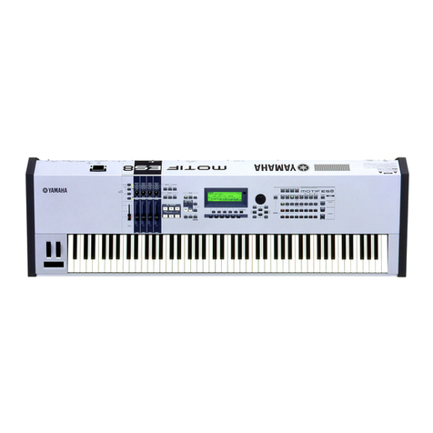
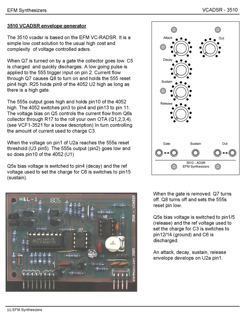
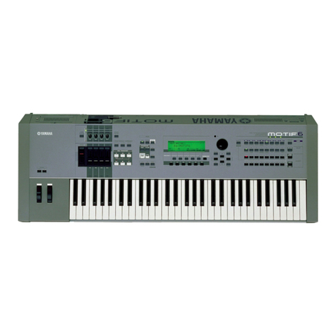
Yamaha Motif XS Series User manual

SERVICE MANUAL
HAMAMATSU, JAPAN
SERVICE MANUAL
MOTIF XS6: 200703-262500
MOTIF XS7: 200703-299250
MOTIF XS8: 200703-378000
SY 011856
Copyright (c) Yamaha Corporation. All rights reserved. PDF ’07.04
SPECIFICATIONS(総合仕様)............................... 4/6
PANEL LAYOUT(パネルレイアウト)....................... 8
CIRCUIT BOARD LAYOUT(ユニットレイアウト)... 14
DISASSEMBLY PROCEDURE
(MOTIF XS6/MOTIF XS7)(分解手順).................... 16
DISASSEMBLY PROCEDURE (MOTIF XS8)
(分解手順)................................................................ 32
INSTALLING OPTIONAL HARDWARE
(拡張部品(別売)の取り付け).......................... 55/59
LSI PIN DESCRIPTION(LSI 端子機能表).............. 63
IC BLOCK DIAGRAM(IC ブロック図)................... 74
CIRCUIT BOARDS(シート基板図)........................ 77
TEST PROGRAM(テストプログラム)...........111/138
SAVING and LOADING A FILE
(ファイルのセーブ&ロード).......................... 165/167
CONTENTS(目次)
FACTORY SET(ファクトリーセット).......... 169/170
FIRMWARE UPDATING PROCEDURES
(ファームウェアバージョンアップ手順)........ 171/173
MOTIF XS BOOT SEQUENCE
(MOTIFXS ブートシーケンス)...................... 175/176
DISPLAY MESSAGES
(メッセージリスト)........................................ 177/179
MIDI IMPLEMENTAION CHART ............................ 181
MIDI DATA FORMAT .............................................. 183
PARTS LIST
BLOCK DIAGRAM(ブロックダイアグラム)
WIRING(基板結線図)
OVERALL CIRCUIT DIAGRAM(総回路図)
•
•
•
MOTIF XS6
MOTIF XS7
MOTIF XS8

MOTIF XS6/MOTIF XS7/MOTIF XS8
2
WARNING
WARNING: CHEMICAL CONTENT NOTICE!
The solder used in the production of this product contains LEAD. In addition, other electrical/electronic and/or plastic (Where applicable)
components may also contain traces of chemicals found by the California Health and Welfare Agency (and possibly other entities) to cause
cancer and/or birth defects or other reproductive harm.
DO NOT PLACE SOLDER, ELECTRICAL/ELECTRONIC OR PLASTIC COMPONENTS IN YOUR MOUTH FOR ANY REASON WHAT SO EVER!
Avoid prolonged, unprotected contact between solder and your skin! When soldering, do not inhale solder fumes or expose eyes to solder/
flux vapor!
If you come in contact with solder or components located inside the enclosure of this product, wash your hands before handling food.
IMPORTANT NOTICE
This manual has been provided for the use of authorized Yamaha Retailers and their service personnel. It has been assumed that basic
service procedures inherent to the industry, and more specifically Yamaha Products, are already known and understood by the users,
and have therefore not been restated.
WARNING : Failure to follow appropriate service and safety procedures when servicing this product may result in personal injury,
destruction of expensive components and failure of the product to perform as specified. For these reasons, we advise
all Yamaha product owners that all service required should be performed by an authorized Yamaha Retailer or the
appointed service representative.
IMPORTANT : This presentation or sale of this manual to any individual or firm does not constitute authorization certification,
recognition of any applicable technical capabilities, or establish a principal-agent relationship of any form.
The data provided is belived to be accurate and applicable to the unit(s) indicated on the cover. The research engineering, and service
departments of Yamaha are continually striving to improve Yamaha products. Modifications are, therefore, inevitable and changes in
specification are subject to change without notice or obligation to retrofit. Should any discrepancy appear to exist, please contact the
distributor’s Service Division.
WARNING : Static discharges can destroy expensive components. Discharge any static electricity your body may have accumulated
by grounding yourself to the ground bus in the unit (heavy gauge black wires connect to this bus.)
IMPORTANT : Turn the unit OFF during disassembly and parts replacement. Recheck all work before you apply power to the unit.
Components having special characteristics are marked and must be replaced with parts having specification equal to those
originally installed.
IMPORTANT NOTICE FOR THE UNITED KINGDOM
Connecting the Plug and Cord
WARNING: THIS APPARATUS MUST BE EARTHED
IMPORTANT. The wires in this mains lead are coloured in accordance with the following code:
GREEN-AND-YELLOW : EARTH
BLUE : NEUTRAL
BROWN : LIVE
As the colours of the wires in the mains lead of this apparatus may not correspond with the coloured markings identifying the terminals in
your plug proceed as follows:
The wire which is coloured GREEN-and-YELLOW must be connected to the terminal in the plug which is marked by the letter E or by the
safety earth symbol or colored GREEN or GREEN-and-YELLOW.
The wire which is coloured BLUE must be connected to the terminal which is marked with the letter N or coloured BLACK.
The wire which is coloured BROWN must be connected to the terminal which is marked with the letter L or coloured RED.
• This applies only to products distributed by Yamaha-Kemble Music (U.K.) Ltd. (3 wires)
印の部品は、安全を維持するために重要な部品です。交換する場合は、安全のために必ず指定の部品をご使用ください。

3
MOTIF XS6/MOTIF XS7/MOTIF XS8
SAVING DATA(データの保存)
Saving and backing up your data
• DRAM data is lost when you turn off the power to the instrument.
Save the data to the flash ROM/a USB storage device/external device such as a computer.
Data stored to the flash ROM may be lost due to malfunction or incorrect operation. Save important data to a USB storage
device/external device such as a computer.
• Never attempt to turn off the power while data is being written to Flash ROM (while an “Executing...” or “Please keep
power on” message is shown). Turning the power off in this state results in loss of all user data and may cause the system
to freeze (due to corruption of data in the Flash ROM). This means that this synthesizer may not be able to start up prop-
erly, even when turning the power on next time.
Backing up the USB storage device/external media
• To protect against data loss through media damage, we recommend that you save your important data onto two USB stor-
age devices/external media.
Be sure to
perform it
作成したデータの保存とバックアップ
DRAM のデータは電源を切ると消えてしまいます。保存しておきたいデータはフラッシュ ROM/USB 記憶装置 / コン
ピューターなどの外部機器に保存してください。
また、フラッシュ ROM に保存 ( ストア ) したデータは故障や誤操作などのために失われることがあります。大切なデー
タは、USB 記憶装置 / コンピューターなどの外部機器に保存してください。
フラッシュ ROM への書き込み中 ( 画面に「Executing...」または「Pleasekeeppoweron.」と表示されます ) に、絶対に
電源を切らないでください。ユーザーメモリー上のデータが失われたりシステムデータが壊れたりして、次に電源を入れ
たときに正常に起動しなくなる恐れがあります。
USB記憶装置 /外部メディアのバックアップ
保存した USB記憶装置 /外部メディアの万一の事故に備えて、大切なデータは予備の USB 記憶装置 / 外部メディアにバッ
クアップとして保存されることをおすすめします。

MOTIF XS6/MOTIF XS7/MOTIF XS8
4
SPECIFICATIONS
Keyboards MOTIF XS8
MOTIF XS7
MOTIF XS6
88 keys, Balanced Hammer Effect Keyboard (Initial Touch/Aftertouch)
76 keys, FSX Keyboard (Initial Touch/Aftertouch)
61 keys, FSX Keyboard (Initial Touch/Aftertouch)
Tone Generator
block
Tone Generato
Polyphon
Multi Timbral
Capacity
16 Parts (internal), Audio Input Parts (A/D, mLAN*)
*1 stereo Part
Voice
GM: 128 Normal Voices + 1 Drum Kit
User: 128 x 3 (selected and copied from Preset bank), Normal Voice + 32 Drum Kits
Performance User: 128 x 3 (up to 4 Parts)
Filter 18 types
Effect System Reverb x 9 types, Chorus x 22 types, Insertion (A, B, L) x 53 types x 8 blocks, Master
Effect x 9 types, Master Equalizer (5 bands), Part EQ (3 bands, stereo)
Sampling block Samples Up to 1,024 Waveforms (Multi Samples)
Up to 128 Key Banks per Waveform
Up to 4,096 Key Banks
Sampling Sources Analog input L/R, Stereo output (Resampling),
mLAN (available on the MOTIF XS6 and 7 when the mLAN16E2 has been installed)
A/D Conversion
D/A Conversion
24-bit, 64 x oversampling
24-bit,128 x oversampling
Sample Data Bits 16
Sampling Frequency 44.1 kHz, 22.05 kHz, 11.025 kHz, 5.5125 kHz (Stereo/Mono)
Sampling Frequency via mLAN (when the mLAN16E2 has been installed): 44.1 kHz (fixed)
Sampling Memory Optionally installed, expandable to 1 GB (512 MB DIMM x 2 slots)
*DIMMs are not installed to the instrument when shipped from the factory.
Sample Length Mono: 32 MB
Stereo: 64 MB
Sampling Time 44.1 kHz: 6 min. 20 sec.
22.05 kHz: 12 min. 40 sec.
11.025 kHz: 25 min. 20 sec.
5.0125 kHz: 55 min. 40 sec.
*Mono/Stereo
Sample Format Original format, WAV, AIFF
Sequencer block Note Capacity Approx. 130,000 notes
Note Resolution 480 ppq (parts per quarter note)
Maximum Polyphony 124 notes
Tempo (BPM) 5 – 300
Recording type Real time replace
Real time overdub (with the exception of the Pattern Chain)
Real time punch in/out (Song only)
Tracks Pattern: 16 Phrase tracks
Pattern Chain: Pattern track, Tempo track, Scene track
Song: 16 sequence tracks (Loop on/off can be set for each track), Tempo track, Scene
track
Patterns 64 Patterns (x 16 sections), Measures: 256 maximum
Mixing Voices: 16 Voices per Pattern and up to 256 Voices for all Patterns
Mixing Templates: 32 for all Songs and Patterns
Phrases User Phrases: 256 per Pattern
Songs 64 Songs
Mixing Voices: 16 Voices per Song and up to 256 Voices for all Songs
Mixing Templates: 32 for all Songs and Patterns
Arpeggio Preset: Approx. 6,000 types
User: 256 types
*MIDI Sync, MIDI transmit/receive channel, Velocity Limit, and Note Limit can be set.
Scene Memory 5 per Song
Sequence Format Original format, SMF format 0, 1 (Format 1 load only)
AWM2, with Expanded Articulation
128 notes
Wave 355 MB (when converted to 16-bit linear format), 2,670 waveforms
Preset: 1,024 Normal Voices + 64 Drum Kits
5
MOTIF XS6/MOTIF XS7/MOTIF XS8
Others Master User: 128
*8 Zones (Master keyboard settings), Assignable Knob/Slider settings, Program Change Table
Sequence Software
compatible with the
Remote Control
function
For Windows®: Cubase 4, SONAR 5.2
For Macintosh®: Cubase 4, Logic 7.2, Digital Performer 5.1
*Functions to be controlled differ depending on the software.
Controllers Pitch Bend wheel, Modulation wheel, Ribbon Controller, Assignable Control Sliders x 8,
Assignable Knobs x 8, Assignable Function buttons x 2, Data dial
Display 320 x 240 dot, 5.7 inch graphic color backlit LCD
Connectors OUTPUT L/MONO, R (standard phone jack)
ASSIGNABLE OUTPUT L, R (standard phone jack)
A/D INPUT L, R (standard phone jack)
DIGITAL OUT
PHONES (standard stereo phone jack)
FOOT CONTROLLER 1, 2
FOOT SWITCH x 2 (SUSTAIN, ASSIGNABLE)
MIDI IN/OUT/THRU
USB (TO HOST, TO DEVICE)
AC IN
ETHERNET
mLAN (MOTIF XS8 only)
Power Consumption 30 W
Dimensions, Weight MOTIF XS8: 1,457 (W) x 466 (D) x 168 (H) mm, 28.6 kg
MOTIF XS7: 1,252 (W) x 391 (D) x 122 (H) mm, 17.0 kg
MOTIF XS6: 1,045 (W) x 391 (D) x 122 (H) mm, 14.8 kg
Accessories AC Power cord, Media (disc) x 1, Owner’s Manual, Data List

MOTIF XS6/MOTIF XS7/MOTIF XS8
6
総合仕様
鍵盤 MOTIF XS8
MOTIF XS7
MOTIF XS6
88鍵BH (バランスドハンマー )鍵盤(イニシャルタッチ/アフタータッチ付)
76鍵FSX鍵盤(イニシャルタッチ/アフタータッチ付)
61鍵FSX鍵盤(イニシャルタッチ/アフタータッチ付)
音源部 音源方式 AWM2+アーティキュレーション機能
最大同時発音数 128音
マルチティンバー数 内蔵音源16パート、オーディオ入力パート(A/D、mLAN*)
*1ステレオパート
波形メモリー 355MB相当 (16bitリニア換算)、2,670ウェーブフォーム
ボイス数 プリセット: 1,024ノーマルボイス+ 64ドラムキット
GM: 128ノーマルボイス+1ドラムキット
ユーザー : 128×3 (プリセットからのピックアップ)ノーマルボイス+32ドラムキット
パフォーマンス数 ユーザー : 128×3音色(最大4パート)
フィルター 18タイプ
エフェクター リバーブ×9タイプ、コーラス×22タイプ、インサーション (A、B、L)×53タイプ×8系統、
マスターエフェクト×9タイプ、マスター EQ (5バンド)、パートEQ (3バンド、ステレオ)
サンプラー部
(DIMM装着時のみ)
最大サンプル数 1,024ウェーブフォーム(マルチサンプル)、ウェーブフォームごとに128キーバンク
合計4,096キーバンク
サンプリングソース アナログ入力L/R、ステレオアウト(リサンプリング)
mLAN (MOTIF XS6/7は、mLANボードmLAN16E2装着時)
A/D変換、D/A変換 A/D変換: 24ビット 64倍オーバーサンプリング
D/A変換: 24ビット128倍オーバーサンプリング
サンプルデータビット 16bit
サンプリング周波数 44.1kHz、22.05kHz、11.025kHz、5.5125kHz (ステレオ/モノ)
<mLAN入力時 (MOTIF XS6/7は、mLANボードmLAN16E2装着時)> 44.1kHz固定
波形メモリー 最大拡張時1GB (512M B DIMM×2)
※工場出荷時にはDIMMは装着されていません。
最大サンプルサイズ 1モノサンプル: 32MB
1ステレオサンプル: 64MB
1回あたりのサンプリング
時間
44.1kHz: 約6分20秒、22.05kHz: 約12分40秒
11.025kHz: 約25分20秒、5.0125kHz: 約55分40秒
※ステレオ/モノいずれの場合でも同様
サンプルフォーマット MOTIF XSオリジナルフォーマット、WAV、AIFF
シーケンサー部 シーケンサー容量 約130,000音
音符分解能 四分音符/480
最大同時録再音数 124音
テンポ(BPM) 5〜300
レコーディング方式 リアルタイムリプレース、リアルタイムオーバーダブ(パターンチェーン除く)、
リアルタイムパンチ(ソングのみ)
トラック数 <パターンモード> フレーズトラック×16
<パターンチェーンモード> パターントラック、テンポトラック、シーントラック
<ソングモード> シーケンサートラック×16 (トラックごとにループ設定可)、
テンポトラック、シーントラック
パターン数 64パターン(×16セクション)
小節数: 最大256
フレーズ数 ユーザーフレーズ: 1パターンあたり256ユーザーフレーズ
ソング数 64ソング
ミキシングボイス: 1ソング/1パターンあたり16個 (最大で256個)
ミキシングテンプレート: 32個

7
MOTIF XS6/MOTIF XS7/MOTIF XS8
シーケンサー部 アルペジエーター プリセット: 約6,000タイプ
ユーザー : 256タイプ
※MIDIシンク、MIDI送受信チャンネル、ベロシティーリミット、ノートリミット設定可
シーンメモリー数 ソングごと5シーンメモリー
シーケンスフォーマット MOTIF XSオリジナルフォーマット
SMFフォーマット0/1 (フォーマット1はロードのみ)
その他 マスターモード設定数 ユーザー : 128設定
※8ゾーン(マスターキーボード設定)、アサイナブルノブ/スライダー設定、プログラムチェンジテーブル
リモート対応ソフトウェア <Windows®> Cubase 4、SONAR 5.2
<Macintosh®> Cubase 4、Logic 7.2、Digital Performer 5.1
※各ソフトウェアの機能によって、リモートコントロールできる内容が異なります。
主な操作子 ピッチベンドホイール×1、モジュレーションホイール×1、リボンコントローラー×1、
アサイナブルコントロールスライダー×8、アサイナブルノブ×8、
アサイナブルファンクションボタン×2、データダイアル×1
ディスプレイ 320×240ドット 5.7インチ グラフィックカラー LCD (バックライト付)
接続端子 OUTPUT L/MONO, R (標準フォーンジャック)、ASSIGNABLE OUTPUT L, R
(標準フォーンジャック)、A/D INPUT L, R(標準フォーンジャック) 、DIGITAL OUT、
PHONES (ステレオ標準フォーンジャック)、FOOT CONTROLLER 1, 2、
FOOT SWITCH×2 (SUSTAIN, ASSIGNABLE)、MIDI IN/OUT/THRU、
USB (TO HOST , TO DEVICE)、AC IN、ETHERNET、mLAN (MOTIF XS8のみ)
消費電力 20W (本体のみ16W)
寸法・質量 MOTIF XS8: 1,457 (W) × 466 (D) × 168 (H) mm、 28.6kg
MOTIF XS7: 1,252 (W) × 391 (D) × 122 (H) mm、17.0kg
MOTIF XS6: 1,045 (W) × 391 (D) × 122(H) mm、14.8kg
電源コード、2P-3P変換器、メディア(disc)×1枚、保証書、取扱説明書、データリスト品属付

MOTIF XS6/MOTIF XS7/MOTIF XS8
8
TONE 2
PAN
TONE 1
MASTER
VOLUME
LOCATE 1 2
ASSIGNABLE
FUNCTION
1
67
ARP FX
REVERB
CHORUS
SELECTED PART
CONTROL
CONTROL
MULTI PART
ON/OFF ON/OFF
EQ LOW EQ MID F
CUTOFF RESONANCE
SWING
QUANTIZE
VAL UE
EQ MID EQ MID Q
ATTACK DECAY
QUANTIZE
STRENGTH GATE TIME
REMOTE ARPEGGIO
EFFECT BYPASS
SEQ TRANSPORT
VOLUME 1VOLUME 2VOLUME 3VOLUME 4VOLUME 5VOLUME 6VOLUME 7VOLUME 8
EQ HIGH PAN
SUSTAIN RELEASE
VELOCITY OCT RANGE
ASSIGN 1 ASSIGN 2
REVERB CHORUS
UNITMULTIPLY
TEMPO
F1 F2
SF1
OCTAVE
MASTER
EFFECT
1
2
UPDOWN
INSERTION SYSTEM
TONE 2
ARP FX
REVERB
CHORUS
PAN
TONE 1
MASTER
VOLUME
LOCATE 1 2
ASSIGNABLE
FUNCTION
CONTROL
12345
67890-
SELECTED PART
CONTROL
MULTI PART
ON/OFF ON/OFF
EQ LOW EQ MID F
CUTOFF RESONANCE
SWING
QUANTIZE
VAL UE
EQ MID EQ MID Q
AT TACK DECAY
QUANTIZE
STRENGTH GATE TIME
REMOTE ARPEGGIO
EFFECT BYPASS
SEQ TRANSPORT
VOLUME 1VOLUME 2VOLUME 3VOLUME 4VOLUME 5VOLUME 6VOLUME 7VOLUME 8
EQ HIGH PAN
SUSTAIN RELEASE
VELOCITY OCT RANGE
ASSIGN 1 ASSIGN 2
REVERB CHORUS
UNITMULTIPLY
TEMPO
F1 F2 F3 F4 F5 F6
SF1 SF2 SF3 SF4 SF5 SF6
OCTAVE
MASTER
EFFECT
1
2
UPDOWN
INSERTION SYSTEM
C3C2B1A1G1F1E1D1C1
C1 D1 E1 F1 G1 A1 B1 C2B0A0G0F0E0
234
7890
F2 F3 F4 F5
F1 SF2 SF3 SF4
S
DEC/NO
EXIT
C
C3
*
2
-
1
6
4
)
0
4)
0
/
/
*
2
-
1
6
A
A'
MOTIF XS6
MOTIF XS7
PANEL LAYOUT(パネルレイアウト)
• Top Panel(トップパネル)

9
MOTIF XS6/MOTIF XS7/MOTIF XS8
1
67
F1 F2
SF1
-
F6
5SF6
EXECUTE
FFO/NOPRATCELESTRAP
DLOHPRAETUMTRAP
FILE UTILITY
SEQUENCER
COMPARE
SEQ
SETUP
SCENE STORE
SECTION
I-P
SECTION
A-H
PERFORMANCE
CONTROL
SUB CATEGORY
MODE
2345
7890
PRE 1 PRE 2 PRE 3 PRE 4 PRE 5 PRE 6 PRE 7 PRE 8
USER 1 USER 2 USER 3 GM DRGM PRE DR USER DR
PROGRAM
ABC DEFGH
-
F2 F3 F4 F5 F6
DEC/NO INC/YES
SONG PATTERN
EDIT JOB STORE
SET LOCATE
CATEGORY SEARCH
PIANO KEYBOARD ORGAN GUITAR BASS BRASSSTRINGS SAX/
WOODWIND
SYN LEAD PA D S /
CHOIRS SYN COMP CHROMATIC
PERCUSSION
DRUM/
PERCUSSION SOUND
EFX
MUSICAL
EFX ETHNIC
8654321 7
910111213141516
COMMON EDIT TRACK
MUTE SOLO
EXIT ENTER
F1 SF2 SF3 SF4 SF5 SF6
MULTI PART
VOICE PERFORM MASTER
INTEGRATED
SAMPLING MIXING
FFO/NOPRATCELESTRAP
DLOHPRAETUMTRAP
FILE UTILITY
SEQUENCER
COMPARE
SEQ
SETUP
SCENE STORE
SECTION
I-P
SECTION
A-H
PERFORMANCE
CONTROL
SUB CATEGORY
MODE
PRE 1 PRE 2 PRE 3 PRE 4 PRE 5 PRE 6 PRE 7 PRE 8 PROGRAM
ABC DEFGH
DEC/NO INC/YES
SONG PATTERN
EDIT JOB STORE
SET LOCATE
8654321 7
910111213141516
COMMON EDIT TRACK
MUTE SOLO
EXIT
MULTI PART
VOICE PERFORM MASTER
INTEGRATED
SAMPLING MIXING
EXECUTE
USER1 USER 2 USER 3 GM DRGM PRE DR USER DR
CATEGORY SEARCH
PIANO KEYBOARD ORGAN GUITAR BASS BRASSSTRINGS SAX/
WOODWIND
SYN LEAD PA D S /
CHOIRS SYN COMP CHROMATIC
PERCUSSION
DRUM/
PERCUSSION SOUND
EFX
MUSICAL
EFX ETHNIC
ENTER
C6C5C4
C6C5C4C3
A
A'

MOTIF XS6/MOTIF XS7/MOTIF XS8
10
MASTER
VOLUME
LOCATE 12
ASSIGNABLE
FUNCTION
1
67
ON/OFF ON/OFF
REMOTE ARPEGGIO
EFFECT BYPASS
SEQ TRANSPORT
F1 F2
SF1
OCTAVE
MASTER
EFFECT
1
2
UPDOWN
INSERTION SYSTEM
TONE 2
PAN
TONE 1
ARP FX
REVERB
CHORUS
SELECTED PART
CONTROL
CONTROL
MULTI PART
EQ LOW EQ MID F
CUTOFF RESONANCE
SWING
QUANTIZE
VALUE
EQ MID EQ M ID Q
ATTACK DECAY
QUANTIZE
STRENGTH GATE TIME
EQ HIGH PAN
SUSTAIN RELEASE
VELOCITY OCT RANGE
ASSIGN 1 ASSIGN 2
REVERB CHORUS
UNITMULTIPLY
TEMPO
VOLUME 1VOLUME 2VOLUME 3VOLUME 4VOLUME 5VOLUME 6VOLUME 7VOLUME 8
C1E0 F0 G0 A0 B0C0 D0 2C1-B1-A C
12345
7890 -
F2 F3 F4 F5 F6
SF1 SF2 SF3 SF4 SF5 SF6
3C
4
)
0
/
*
2
-
1
6
B
B'
MOTIF XS8
qKeyboard
wPitch Bend wheel
eModulation wheel
rRibbon Controller
t[ASSIGNABLE FUNCTION 1, 2] buttons
y[MASTER VOLUME]
uControl rotary knobs
i[SELECTED PART CONTROL] button
o[MULTI PART CONTROL] button
!0 Control Sliders [VOLUME 1-8]
!1 [REMOTE ON/OFF] button
!2 [ARPEGGIO ON/OFF] button
!3 [EFFECT BYPASS] buttons
!4 [MASTER EFFECT] button
!5 [OCTAVE DOWN, UP] buttons
!6 [SEQ TRANSPORT] buttons
[
] (Top) button
[
] (Reverse) button
[
] (Forward) button
[
] (Record) button
[
] (Stop) button
[
] (Play) button
q鍵盤
wピッチベンドホイール
eモジュレーションホイール
rリボンコントローラー
t[ASSIGNABLEFUNCTION1,2](アサイナブルファンクション)
ボタン
y[MASTERVOLUME](マスターボリューム)スライダー
uコントロールロータリーノブ
i[SELECTEDPARTCONTROL](セレクテッドパート
コントロール)ボタン
o[MULTIPARTCONTROL](マルチパートコントロール)ボタン
!0 コントロールスライダー [VOLUME1 〜 8]
!1 [REMOTEON/OFF](リモートオン/オフ)ボタン
!2 [ARPEGGIOON/OFF](アルペジオオン/オフ)ボタン
!3 [EFFECTBYPASS](エフェクトバイパス)ボタン
!4[MASTEREFFECT](マスターエフェクト)ボタン
!5[OCTAVEDOWN,UP](オクターブダウン、アップ)ボタン
!6[SEQTRANSPORT](シーケンサートランスポート)ボタン
[
](トップ)ボタン
[
](リワインド)ボタン
[](フォワード)ボタン
[
](レコード)ボタン
[
](ストップ)ボタン
[
](プレイ)ボタン
• Top Panel(トップパネル)

11
MOTIF XS6/MOTIF XS7/MOTIF XS8
2
1
67
O
RT
F1 F2
SF1
A
STER
F
FECT
C
FFO/NOPRATCELESTRAP
DLOHPRAETUMTRAP
FILE UTILITY
SEQUENCER
COMPARE
SEQ
SETUP
SCENE STORE
SECTION
I-P
SECTION
A-H
PERFORMANCE
CONTROL
SUB CATEGORY
MODE
12345
7890
PROGRAM
ABC DEFGH
-
F2 F3 F4 F5 F6
DEC/NO INC/YES
SONG PATTERN
EDIT JOB STORE
SET LOCATE
8654321 7
910111213141516
COMMON EDIT TRACK
MUTE SOLO
EXIT ENTER
SF1 SF2 SF3 SF4 SF5 SF6
MULTI PART
VOICE PERFORM MASTER
EXECUTE
INTEGRATED
SAMPLING MIXING
PRE 1 PRE 2 PRE 3 PRE 4 PRE 5 PRE 6 PRE 7 PRE 8
USER 1 USER 2 USER 3 GM DRGM PRE DR USER DR
CATEGORY SEARCH
PIANO KEYBOARD ORGAN GUITAR BASS BRASSSTRINGS SAX/
WOODWIND
SYN LEAD PADS/
CHOIRS SYN COMP CHROMATIC
PERCUSSION
DRUM/
PERCUSSION SOUND
EFX
MUSICAL
EFX ETHNIC
7C6C5C4C3C
B
B'
!7 LCD Display
!8 [F1] – [F6] (Function) buttons
!9 [SF1] – [SF5] (Sub Function) buttons
@0 Data dial
@1 [INC/YES] button
@2 [DEC/NO] button
@3 Cursor buttons
@4 [EXIT] button
@5 [ENTER] button
@6 [MODE] buttons
@7 Bank buttons
@8 Group [A] – [H] buttons
@9 Number [1] – [16] buttons
#0 [COMMON EDIT] button
#1 [PROGRAM] button
#2 [CATEGORY SEARCH] button
#3 [PERFORMANCE CONTROL] button
#4 [TRACK] button
#5 [MUTE] button
#6 [SOLO] button
#7 Studio Connections logo
!7LCD(液晶ディスプレイ)
!8[F1] 〜 [F6](ファンクション)ボタン
!9 [SF1] 〜 [SF6](サブファンクション)ボタン
@0 データダイアル
@1 [INC/YES](インク/イエス)ボタン
@2 [DEC/NO](デック/ノー )ボタン
@3 カーソルボタン
@4 [EXIT](エグジット)ボタン
@5 [ENTER](エンター )ボタン
@6 [MODE](モード)ボタン
@7 バンクボタン
@8 グループ[A] 〜 [H]ボタン
@9 ナンバー[1] 〜 [16]ボタン
#0 [COMMONEDIT](コモンエディット)ボタン
#1 [PROGRAM](プログラム)ボタン
#2[CATEGORYSEARCH](カテゴリーサーチ)ボタン
#3[PERFORMANCECONTROL](パフォーマンスコントロール)ボタン
#4[TRACK](トラック)ボタン
#5[MUTE](ミュート)ボタン
#6[SOLO](ソロ)ボタン
#7StudioConnectionsロゴ

MOTIF XS6/MOTIF XS7/MOTIF XS8
12
POWER
ON/ OFF
AC IN
LCD CONTRASTETHERNET
USB
TO DEVI CETO HOST
POWER
ON/ OFF
AC IN
LCD CONTRASTETHERNET
USB
TO DEVICETO HOS T
POWER
ON/ OFF
AC IN
USB
TO DEVICETO HOS T LCD CONTRASTETHERNET
/
)01
24
MOTIF XS6
MOTIF XS7
MOTIF XS8
/
)01
24
/
)01
6
4
C
C'
• Rear Panel(リアパネル)
q[POWER ON/OFF] switch
w[AC IN] (AC Power Cord Socket)
e[ETHERNET] connector
r[USB] connectors
t[LCD CONTRAST] Control
y[mLAN 1, 2] (IEEE 1394) connectors
(only MOTIF XS8)
umLAN expansion board (mLAN16E2)
cover (MOTIF XS6, MOTIF XS7)
i[DIGITAL OUT] connector
q[POWERON/OFF](パワーオン/オフ)スイッチ
w[ACIN](ACイン)端子
e[ETHERNET](イーサーネット)端子
r[USB]端子
t[LCDCONTRAST](LCDコントラスト)ノブ
y[mLAN1,2](IEEE1394)端子
(MOTIFXS8のみ)
umLAN拡張ボード(mLAN16E2)取り付け口
(MOTIFXS6/7のみ)
i[DIGITALOUT](デジタルアウトプット)端子

13
MOTIF XS6/MOTIF XS7/MOTIF XS8
THRU
MIDI
OUT IN PHONES
ASSIGNABLE SUSTAIN
FOOT SWITCH FOOT CONTROLLER
21
ASSIGNABLE OUTPUT OUTPUT
RRLL/MONO
DIGITAL OUT
A/D INPUT
RLGAIN
THRU
MIDI
OUT IN PH ONESPH ONES
ASSIGNABLE SUSTAIN
FOOT SWITCH FOOT CONTROLLER
21
ASSIGNABLE OUTPUT OUTPUT
RR L L/MONO
DIGITAL OUT
A/D INPUT
RLGAIN
THRU
MIDI
OUT IN PH ONESPH ONES
ASSIGNABLE SUSTAIN
FOOT SWITCH FOOT CONTROLLER
21
ASSIGNABLE OUTPUT OUTPUT
RR L L/MONO
DIGITAL OUT
A/D INPUT
RLGAIN
*-
*-
*-
C
C'
o[MIDI IN, OUT, THRU] connectors
!0 [FOOT SWITCH] jacks
!1 [FOOT CONTROLLER 1, 2] jacks
!2 [ASSIGNABLE OUTPUT L, R] jacks
!3 [OUTPUT L/MONO, R] jacks
!4 [PHONES] (Headphone) jack
!5 [A/D INPUT L, R] jacks
!6 [GAIN] knob
o[MIDIIN,OUT,THRU]端子
!0 [FOOTSWITCH](フットスイッチ)端子
!1 [FOOTCONTROLLER1,2](フットコントローラー 1,2)端子
!2
[ASSIGNABLEOUTPUTL,R](アサイナブルアウトプット左、右)端子
!3 [OUTPUTL/MONO,R](アウトプット左/モノラル、右)端子
!4[PHONES](ヘッドフォン)端子
!5[A/DINPUTL,R](A/Dインプット左、右)端子
!6[GAIN](ゲイン)ノブ

MOTIF XS6/MOTIF XS7/MOTIF XS8
14
CIRCUIT BOARD LAYOUT(ユニットレイアウト)
PNA PNC
DM
PNB-PN
PNB-BLG
LCD
(液晶ディスプレイ)
JKAN-LC
MK61L MKH-D
JKAN-JA
• MOTIF XS6/XS7
<XS7 Keyboard assembly (FSX鍵盤) >
* This figure shows the MOTIF XS6.
(このイラストはMOTIFXS6を表しています。)
PNB-RB
Powewr supply unit
(電源ユニット)
Wheel assembly
(ホイールAss’y)
Touch volume
(タッチボリューム)
MKC MKH-DMK76L
EMKS-FD
EMKS-FD
JKAN-ML

15
MOTIF XS6/MOTIF XS7/MOTIF XS8
PNA PNC
DM
PNB-PN
PNB-BLG
MLAN
LCD
(液晶ディスプレイ)
JKAN-LC
GHD EBUS L HEDaf H
JKAN-JA
• MOTIF XS8
HEDaf M
MK SUB GHDPC
PNB-RB
Powewr supply unit
(電源ユニット)
Wheel assembly
(ホイールAss’y)
Touch volume
(タッチボリューム)
JKAN-ML

MOTIF XS6/MOTIF XS7/MOTIF XS8
16
1. Side Panel R, Side Panel L
(サイドパネル R,サイドパネル L)..........................17
2. Control Panel Assembly(コンパネ Assy)..........17
3. JKAN-JA Circuit Board(JKAN-JA シート)..........18
4. DM Circuit Board(DM シート).............................18
5. JKAN-ML Circuit Board(JKAN-ML シート).........20
6.
Power Supply Unit, AC-IN Connector, Power Switch
(電源ユニット、AC インレット、電源スイッチ)...........20
7. Display Assembly(ディスプレイ Assy).............21
8. JKAN-LC Circuit Board, LCD
(JKAN-LC シート、液晶ディスプレイ)..................21
9. PNA Circuit Board(PNA シート)..........................22
10. PNB-PN Circuit Board(PNB-PN シート).............23
11. PNC Circuit Board(PNC シート)..........................24
12. End Block R(拍子木 R).........................................25
13. PNB-RB Circuit Board, Wheel Assembly
(PNB-RB シート、ホイール Assy)...........................25
14. End Block L, Touch Volume
(拍子木 L、タッチボリューム)................................25
15. Keyboard Assembly(FSX 鍵盤 D).......................27
16. Keys (White and Black Keys)
(鍵盤(白鍵、黒鍵))...............................................27
17. Installing Keys (Black and White Keys)
(鍵盤(黒鍵、白鍵)の取り付け)............................29
18. Disassembling Keyboard Assembly
(FSX 鍵盤 D の分解)................................................29
18-1 Rubber Contact(接点ゴム)...................................29
18-2 MK61L Circuit Board (MOTIF XS6 only)
(MK61L シート(MOTIFXS6 のみ))......................30
18-3 MK76L Circuit Board (MOTIF XS7 only)
(MK76L シート(MOTIFXS7 のみ))......................30
18-4 MKC Circuit Board (MOTIF XS7 only)
(MKC シート(MOTIFXS7 のみ))..........................31
18-5 MKH-D Circuit Board, EMKS-FD Circuit Board
(MKH-D シート、EMKS-FD シート)......................31
DISASSEMBLY PROCEDURE (MOTIF XS6/MOTIF XS7)(分解手順)
The unit is heavy. Treat the unit with enough care
when lifting it up.
If you want to turn the unit or control panel
assembly upside down, prepare supporting
materials and put the unit or control panel on them
with the end portions of the unit or control panel
placed on the supporting materials. (Fig. A)
Attach the filament tapes in the same way as they
were before removal.
When removing buttons attached to the PNA
circuit board, PNB-PN circuit board or PNC circuit
board, be careful not to damage the buttons. Hold
side faces of a button to handle it with relative
safety.
Notes on Flat Cable
Contacts are visible through the back side. When
connecting to the connector, pay attention not to
insert the cable inversely. (Photo A)
During assembly, pay attention that connectors,
cables or the like are not pinched by circuit
boards, frames, etc.
•
•
•
•
•
•
本体の重量が大きいため、持ち上げるときは十分注意
してください。
本体またはコンパネ Assy を裏向きにして作業する
ときは、両端に枕木を敷いてください。(図 A)
フィラメントテープは、取り外す前と同じように取り
付けてください。
PNA シート、PNB-PN シート、PNC シートそれぞれ
から付属のボタンを外すときは、ボタンを損傷しない
ように十分注意してください。ボタンの側面を持つと
比較的安全です。
フラットケーブルの注意
接点が裏面から透けて見えます。コネクタにケーブル
の表・裏を逆に差し込まないように注意して取り付け
てください。(写真 A)
組み立てるときは、基板やフレームなどでコード類を
はさまないように注意してください。
•
•
•
•
•
•
Precautions(注意事項)
PhotoA( 写真 A) Fig.A( 図 A)

17
MOTIF XS6/MOTIF XS7/MOTIF XS8
<Bottom view>
<Top view>
<Rear view>
<Right side view>
Side panel R
(サイドパネルR)
Side panel L
(サイドパネルL)
Side panel L
(サイドパネルL)
[40A]
[40C]
[40B]
[40A]
[30A]
[40C]
[40C]
[40C]
[30A]
Side panel R
(サイドパネルR)
* This figure shows the MOTIF XS6.(この図は MOTIFXS6 です。)
1. Side Panel R, Side Panel L
(Time required: About 1 minute each)
1-1 Remove the five (5) screws marked [40A]. The
side panel R can then be removed. (Fig. 1)
* The side panel L can be removed in the same
manner.
2. Control Panel Assembly
(Time required: About 4 minutes)
2-1 Turn the unit upside down and remove the three (3)
screws marked [40B]. (Fig. 1)
2-2 Remove the side panel R and side panel L. (See
procedure 1.)
2-3 Remove the seven (7) screws marked [30A] and
six (6) screws marked [40C]. (Fig. 1)
1. サイドパネル R,サイドパネル L
(所要時間:各約 1 分)
1-1 [40A] のネジ 5 本を外して、サイドパネル R を外
します。(図 1)
※ サイドパネル L も同様にして外すことができます。
2. コンパネ Assy(所要時間:約 4 分)
2-1 本体を裏向きにして、[40B]のネジ3 本を外します。
(図 1)
2-2 サイドパネル R とサイドパネル L を外します。
(1 項参照)
2-3 [30A] のネジ 7 本と [40C] のネジ 6 本を外します。
(図1)
[30A]: BindHeadTappingScrew-B(B タイト+ BIND)4.0X8MFZN2B3(WE962000)
[40A],[40B],[40C]: BindHeadTappingScrew-S(S タイト+ BIND)3.0X8MFZN2B3(WE877800)
Fig.1( 図 1)

MOTIF XS6/MOTIF XS7/MOTIF XS8
18
(パネル支持金具)
Panel holder
Insert into 2 holes
Control panel assembly
(コンパネAssy)
<Right side view>
(2箇所差し込み)
2
1
Installing the service stay(ステイの取り付け方)
1.ステイの先端をシールド板 L の切り込みに挿入し、切り込みの奥で引っ掛けます。
2.コンパネ Assy の A 部にステイを掛けます。
1. Insert the end of the stay into the slot of the shield plate L and engage the stay at the end of the slot.
2. Make the other end of the stay in engagement with the portion A of the control panel assembly.
A
Service stay (V6295700)
(サービス用ステイ)
2-4
Insert your fingers under the middle portion of the
control panel assembly and open to the position
shown in Fig. 3 and then pull the control panel
assembly in the direction of the white arrow in Fig. 3.
(Fig. 2, 3)
*
When installing the control panel assembly, tilt
the control panel assembly as shown in Fig. 3 and
insert the panel holders into the two holes. (Fig. 3)
* When closing the control panel assembly, take
care not to pinch connector assemblies.
3. JKAN-JA Circuit Board
(Time required: About 4 minutes)
3-1 Remove the side panel R and side panel L. (See
procedure 1.)
3-2 Open the control panel assembly (see procedure 2)
and use the service stay (V6295700) to make the
panel secured. (Photo 1)
3-3 Remove the nine (9) screws marked [370], the
screw marked [385] and two (2) screws marked
[390]. The JKAN-JA circuit board can then be
removed. (Fig. 4)
4. DM Circuit Board
(Time required: About 4 minutes)
4-1 Remove the side panel R and side panel L. (See
procedure 1.)
4-2 Open the control panel assembly. (See procedure
3-2.)
4-3 Remove the connector assembly from the cable
clamp on the DM cover.
2-4 コンパネ Assy の中央部に指を掛けて図 3 の位置
まで開き、コンパネ Assy を図 3 の白矢印の方向
に引き上げて外します。(図 2、図 3)
※ コンパネ Assy を取り付けるときは、コンパネ
Assy を図 3 のように斜めにして、2 個所の穴に
パネル支持金具を差し込んでください。(図 3)
※ コンパネ Assy を閉めるときは、束線を挟まない
よう注意してください。
3. JKAN-JA シート(所要時間:約 4 分)
3-1 サイドパネル R とサイドパネル L を外します。
(1 項参照)
3-2 コンパネ Assy を開き(2 項参照)、サービス用の
ステイ(V6295700)でパネルを固定します。(写真 1)
3-3 [370] のネジ 9 本と [385] のネジ 1 本、[390] のネ
ジ 2 本を外して、JKAN-JA シートを外します。(図 4)
4. DM シート(所要時間:約 4 分)
4-1 サイドパネル R とサイドパネル L を外します。
(1 項参照)
4-2 コンパネ Assy を開きます。(3-2 項参照)
4-3 カバー DM 上のケーブルクランプから束線を外し
ます。
Fig.3( 図 3)
Fig.2( 図 2)
Photo1( 写真 1)

19
MOTIF XS6/MOTIF XS7/MOTIF XS8
<Top view>
<Rear view>
JKAN-JA
[390] [385] [350] [270][350]
[350]
DM cover
(カバーDM)
DM earth plate
(DMアースプレート)
Earth plate B
(アースプレートB)
PS guard
(ガードPS) [270][270][267]
[370] [370]
[350]
DM
<Top view>
[320] [210]
(電源ユニット)
Power supply unit
[230][230]
[200] [200] [310]
(ACIN束線)
AC IN connector assembly
(ACインレット)
AC-IN connector
(電源スイッチ)
Power switch
<Rear view>
[310]
(ACインレット)
AC-IN connector
(電源スイッチ)
Power switch
[190]
(PSWアングル)
Power switch holder
• AC IN connector assembly(ACIN束線)
* This figure shows the MOTIF XS7.(この図は MOTIFXS7 です。)
Fig.4( 図 4)
[267]:CupScrew-B(B タイト+ CUP)3.0X8MFZN2W3(WK386600)
[270]:BindHeadTappingScrew-B(B タイト+ BIND)3.0X6MFZN2W3(WE936300)
[350]:BindHeadTappingScrew-B(B タイト+ BIND)3.0X6MFZN2W3(WE936300)
[370]:BindHeadTappingScrew-B(B タイト+ BIND)3.0X10MFZN2B3(WE972200)
[385]:CupScrew-B(B タイト+ CUP)3.0X8MFZN2W3(WK386600)
[390]:BindHeadTappingScrew-B(B タイト+ BIND)3.0X6MFZN2W3(WE936300)
Fig.5( 図 5)
[190]:BindHeadScrew(小ネジ+ BIND)3.0X6MFZN2B3(WE878300)
[200]:BindHeadTappingScrew-B(B タイト+ BIND)3.0X10MFZN2B3(WE972200)
[210]:BindHeadTappingScrew-S(S タイト+ BIND)4.0X8MFZN2W3(WE941800)
[230]:BindHeadTappingScrew-B(B タイト+ BIND)3.0X6MFZN2W3(WE936300)
[310]:BindHeadScrew(小ネジ+ BIND)3.0X6MFZN2B3(WE878300)
[320]:BindHeadTappingScrew-B(B タイト+ BIND)3.0X6MFZN2W3(WE936300)
4-4 [350] のネジ 11 本を外して、カバー DM とアース
プレート B、DM アースプレートを外します。(図 4)
4-5 [310] の ネ ジ 5 本 と [320] の ネ ジ 1 本 を 外 し て、
DM シートを外します。(図 5)
※ DM シートを交換するときに、CN705 と CN706
に拡張基板が差し込まれていれば、DM シートか
ら拡張基板を外してから交換してください。
※ DM シートを交換した場合は MACAddress の書
き込みを行ってください。詳しくは 140 ページを
参照してください。
4-4 Remove the eleven (11) screws marked [350]. The
DM cover, earth plate B and DM earth plate can
then be removed. (Fig. 4)
4-5 Remove the five (5) screws marked [310] and the
screw marked [320]. The DM circuit board can
then be removed. (Fig. 5)
* If you find extension circuit boards attached
to the CN705 and CN706 when replacing the
DM circuit board, remove the extension circuit
boards from the DM circuit board and then re-
place the DM circuit board.
* If you replaced the DM circuit board, execute
MAC Address writing. See page 113 for details.

MOTIF XS6/MOTIF XS7/MOTIF XS8
20
mLAN support angle
(mLANサポート金具)
[290]
JKAN-ML
[30B]
mLAN cover(mLAN 蓋)
<Rear view>
* This figure shows the MOTIF XS7.(この図は MOTIFXS7 です。)
5. JKAN-ML Circuit Board
(Time required: About 6 minutes)
5-1 Remove the side panel R and side panel L.
(See procedure 1.)
5-2 Open the control panel assembly.
(See procedure 3-2.)
5-3 Remove the DM circuit board. (See procedure 4.)
5-4
Remove the four (4) screws marked [290]. The
JKAN-ML circuit board can then be removed. (Fig. 6)
* When installing the JKAN-ML circuit board, fit
the notch of the mLAN support angle to the
notch of the JKAN-ML circuit board.
* If the mLAN16E2 is inserted, remove the
mLAN16E2 and then remove the JKAN-ML
circuit board.
• Removing the mLAN16E2
a-1 Remove the two (2) screws marked [30B] and
remove the mLAN cover. The mLAN16E2 can
then be removed. (Photo 2)
6.
Power Supply Unit, AC-IN Connector,
Power Switch
(Time required: About 6 minutes)
6-1 Remove the side panel R and side panel L.
(See procedure 1.)
6-2 Open the control panel assembly.
(See procedure 3-2.)
6-3 Remove the screw marked [267] and five (5)
screws marked [270]. The PS guard can then be
removed. (Fig. 4)
6-4
Power Supply Unit (Time required: About 6 minutes)
6-4-1 Remove the five (5) screws marked [230]. The
power supply unit can then be removed. (Fig. 5)
6-5 AC-IN Connector, Power Switch
(Time required: About 5 minutes)
6-5-1 Remove the four (4) screws marked [200] and
the screw marked [210]. The AC IN connector
assembly can then be removed. (Fig. 5)
6-5-2 Remove the AC-IN connector from the AC IN
connector assembly. (Fig. 5)
6-5-3 Remove the two (2) screws marked [190] and
remove the power switch holder from the AC IN
connector assembly. The power switch can then
be removed. (Fig. 5)
5. JKAN-ML シート(所要時間:約 6 分)
5-1 サイドパネル R とサイドパネル L を外します。
(1 項参照)
5-2 コンパネ Assy を開きます。(3-2 項参照)
5-3 DM シートを外します。(4 項参照)
5-4 [290] のネジ 4 本を外して、JKAN-ML シートを外
します。(図 6)
※ JKAN-ML シートを取り付けるときは、mLAN サ
ポート金具の切りかきと JKAN-ML シートの切り
かきをはめ合わせて取り付けてください。
※ mLAN16E2 が挿入されている場合は、mLAN16E2
を取り外してから JKAN-ML シートを外してくだ
さい。
•mLAN16E2 の外し方
a-1 [30B] の ネ ジ 2 本 を 外 し て mLAN 蓋 を 外 し、
mLAN16E2 を取り外します。(写真 2)
6. 電源ユニット、AC インレット、
電源スイッチ(所要時間:約 6 分)
6-1 サイドパネル R とサイドパネル L を外します。
(1 項参照)
6-2 コンパネ Assy を開きます。(3-2 項参照)
6-3 [267] のネジ 1 本と [270] のネジ 5 本を外してガー
ド PS を外します。(図 4)
6-4 電源ユニット(所要時間:約 6 分)
6-4-1 [230] のネジ 5 本を外して、電源ユニットを外し
ます。(図 5)
6-5 AC インレット、電源スイッチ(所要時間:約 5 分)
6-5-1 [200] の ネ ジ 4 本 と [210] の ネ ジ 1 本を外して、
ACIN 束線を外します。(図 5)
6-5-2 ACIN 束線から AC インレットを外します。(図 5)
6-5-3 [190] のネジ 2 本を外して、ACIN 束線から PSW
アングルを外してから、電源スイッチを外します。
(図5)
Fig.6( 図 6)
[290]:BindHeadTappingScrew-B(B タイト+ BIND)
3.0X6MFZN2W3(WE936300)
Photo2( 写真 2)
[30B]:BindHeadScrew(小ネジ+ BIND)4.0X6MFZN2B3(WE878400)
This manual suits for next models
3
Table of contents
Other Yamaha Synthesizer manuals

Yamaha
Yamaha PF-85 User manual

Yamaha
Yamaha CP-20 User manual

Yamaha
Yamaha CS01 User manual

Yamaha
Yamaha P-120 User manual

Yamaha
Yamaha Loopfactory DX200 User manual

Yamaha
Yamaha MODX6 User manual

Yamaha
Yamaha DS-55 User manual

Yamaha
Yamaha PF2000 User manual

Yamaha
Yamaha Harmony Director HD-300 Operating manual

Yamaha
Yamaha CS-30 User manual

Yamaha
Yamaha SY-77 User manual

Yamaha
Yamaha DX21 Quick start guide

Yamaha
Yamaha SY85 User manual

Yamaha
Yamaha AN1x Instruction Manual

Yamaha
Yamaha YP-10 User manual

Yamaha
Yamaha P-150 User manual

Yamaha
Yamaha P-120 User manual

Yamaha
Yamaha EOS B700 User manual

Yamaha
Yamaha CX5M User manual

Yamaha
Yamaha PortaTone PSR-400 User manual