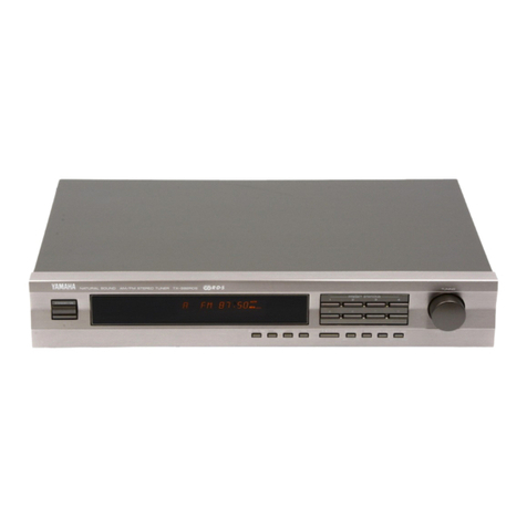
Yamaha T-1000 User manual

E
$:
E
pests
Seu
nessa
pester
E
f
pelleted
eed
toe
an
TRS
poe
taint
AAK
Sari
e
`
ATRA
nega.
r
poema
7
:
eae
Pe
ñ
o
E
TN
;
E
E
eae
Exo
wer
tease
rs
i :
3
SARETE
REET
U
y,
or
i
j
p
é
nu
E
Rea
5;
ss)
5
E
H
ia
Pew
ac
wages
i
y
itis
:
ae
yen
plait
Soa
srr
ee:
ze
5
ma
;
i
g
ees
aig
goat
A
nat
eo
Sr
Sac
;
4
ate
$
AP
y
4
AEBS
$
ss
4
;
i
pS
$
4
A
:
à
a
e
i
E
-o
o
AR
oi
ai
cate
i
sta
ARI
f;
shit
i
pee
aera
4
aS
neces
age
aes
Bia
Y
ES
ees
38
A
ees
EiS
as
7
Paes
ERA
7
NEARTAN
:
Spacer
Ronee
ca
ane
a
pen
+
:
ee
eatin
ARO
y
OM
:
-
Peeps
: >
E
ES
A
ARE
GIES
a
if
EAN
ae
ed
$
SEDE
:
pias
2
20
2
Bs
E
s
i
of
feels
caw
Serial
No.
e
,
The
serial
number
is
located
on
the
rear
of
the
chassis.
e
7
3
Retain
this
Owner’s
Manual
in
a
safe
place
for
future
reference.
-
WARNING
3
To
prevent
fire
or
shock
hazard
do
not
expose
this
appliance
to
rain
or
moisture.
. . .
»
.
»
.
.
. .
‘
.
.
a
»
>
.
.
.
. .
.
»
.
L
*
. .
. . . `
—
=
-à

A
PS
CAUJTION
(PREPARED
IN
ACCORDANCE
WITH
UL
STANDARD
1270)
1
Read
Instructions
—
All
the
safety
and
operating
instructions
should
be
read
before
the
appliance
is
operated.
2
Retain
instructions
—
The
safety
and
operating
instructions
should
be
retained
for
future
reference.
3
Heed
Warnings
—
All
warnings
on
the
appliance
and
in
the
operating
instructions
should
be
adhered
to.
A
Follow
Instructions
—
All
operating
and
other
instruc-
tions
should
be
followed.
=)
Water
and
Moisture
—
The
appliance
should
not
be
used
near
water
—
for
example,
near
a
bathtub,
washbowl,
kitchen
sink,
laundry
tub,
in
a
wet
basement,
or
near
swimming
pool,
etc.
i
pagni
Gb
Carts
and
Stands
-
—
The
appliance
shauld
be
used
only
with
a
cart.
or
stand
that
is
recommended
by,
the
manufac-
turer..
i
7
\
Wall
or
Ceiling
Mounting
—
The
appliance
should
be
mounted
to
a
wail
or
ceiling
only
as
recommended
by
the
manufacturer.
E
Ventilation
—
The
appliance
should
be
situated
so
that
its
locat.on
or
position
does
not
interfere
with
its
proper
ventilation.
For
example,
the
appliance
should
not
be
situated
on
a
bed,
sofa,
rug,
or
similar
surface
that
may
block
the
ventilation
openings;
or
placed
in
a
built-in
installa-
tion,
such
as
a
bookcase
or
cabinet
that
may
impede
the
flow
of
air
through
the
ventilation
openings.
g
Heat
—
The
appliance
should
be
situated
away
from
heat
sources
such
as
radiators,
stoves,
or
other
appliances
that
preduce
heat.
“|
O
Power
Sources
—
The
appliance
should
be
connect-
ed
to
a
power
supply
only
of
the
type
described
in
the
operating
instructions
or
as
marked
on
the
appliance.
1 1
Power-Cord
Protection
—
Power-supply
cords
shouid
be
routed
so
that
they
are
not
likely
to
be
walked
on
or
pinched
by
items
placed
upon
or
against
them,
paying
particular
attention
to
cords
at
plugs,
convenience
receptacles,
and
the
point
where
they
exit
from
the
appliance.
1
aa]
Cleaning
—
The
appliance
should
be
cleaned
only
as
recommended
by
the
manufacturer.
4
3
Nonuse
Periods
—
The
power
cord
of
the
appliance
should
be
unplugged
from
the
outlet
when
left
unused
for
a
long
period
of
time.
q
A
Object
and
Liquid
Entry
—
Care
should
be
taken
so
that
objects
do
not
fall
into
and
liquids
not
spilled
into
the
inside
of
the
appliance.
4
ES
Damage
Requiring
Service
—
The
appliance
should
be
serviced
by
qualified
service
personnel
when:
A.
The
power-supply
cord
or
the
plug
has
been
damaged;
or
B.
Objects
have
failen,
or
liquid
has
been
spilled
into
the
appliance;
or
C.
The
appliance
has
been
exposed
to
rain;
or
D.
The
appliance
does
not
appear
to
operate
normally
or
exhibits
a
marked
change
in
performance;
or
The
appliance
has
been
dropped,
or
the
cabinet
damag-
ed.
Mm
1
6
Servicing
—
The
user
shouid
not
attempt
to
service
the
appliance
beyond
those
means
described
in
the
operat-
ing
instructions.
All
other
servicing
shouid
be
referred
to
qualified
service
personnel.
4
/
Power
Lines
—
An
outdoor
antenna
should
be
jocated
away
from
power
lines.
1
S
Outdoor
antenna
grounding
—
|f
an
outside
antenna
is
connected
to
the
tuner,
be
sure
the
antenna
system
is
grounded
so
as
to
provide
some
protection
against
voltage
surges
and
built
up
static
charges.
Section
810
of
the
National
Electrical
Code,
ANSI/NFPA
No.
70
—
1981,
provides
information
with
respect
to
proper
grounding
of
the
mast
and
supporting
structure,
grounding
of
the
lead-in
wire
to
an
antenna
discharge
unit,
size
of
grounding
con-
ductors,
location
of
antenna-discharge
unit,
connection
to
grounding
electrodes,
and
requirements
for
the
grounding
electrode.
EXAMPLE
OF
ANTENNA
GROUNDING
AS
PER
NATIONAL
ELECTRICAL
CODE
INSTRUCTIONS
Antenna.
b
Lead-in
Wire
To
Tuner
or
Receiver
Antenna
Discharge
~~
Ground
Unit
c
Ground
,
y
Wire,
y
Wire
:
Ground
frat
Clamps
Grounding
y
Electrode
Driven
SB1682
8’
into
the
Earth
(2.44
Meters)
a.
Use
No.
10
AWG
(5.3
mm?)
copper,
No.
8
AWG
(8.4
mm?)
aluminium,
No.
17
AWG
(1.0
mm?)
copper-clad
steel
or
bronze
wire,
or
larger,
as
ground
wire.
b.
Secure
antenna
lead-in
and
ground
wire
to
house
with
stand-off
insulators
spaced
from
4
feet
(1.22
meters)
to
6
feet
(1.83
meters)
apart.
c.
Mount
antenna
discharge
unit
as
closely
as
possible
to
where
lead-in
enters
house.

ATT
RISK
OF
ELECTRIC
SHOCK
DO
NOT
OPEN
CAUTION:
TO
REDUCE
THE
RISK
OF
l
ELECTRIC
SHOCK,
DO
NOT
REMOVE
COVER
(OR
BACK).
NO
USER-SERVICEABLE
PARTS
INSIDE.
REFER
SERVICING
TO
QUALIFIED
SERVICE
PERSONNEL.
ə
Explanation
of
Graphical
Symbols
The
lightning
flash
with
arrowhead
symbol,
within
an
equilateral
triangle,
is
intended
to
alert
you
to
the
presence
of
uninsulated
"dangerous
voltage”
within
the
product's
enclosure
that
may
be
of
sufficient
magnitude
to
constitute
a
risk
of
electric
shock
to
persons.
The
exclamation
point
within
an
equilateral
triangle
is
intended
to
alert
you
to
the
presence
of
important
operating
and
maintenance
{servicing}
instructions
in
the
literature
accom-
panying
the
appliance.
The
T-1000
is
a
sophisticated
AM/FM
stereo
tuner.
To
ensure
proper
operation
for
the
best
possible
performance,
please
read
this
manual
carefully.
2
Choose
the
installation
location
of
your
T-1000
carefully.
Avoid
placing
it
in
direct
sunlight
or
close
to
a
source
of
heat.
Also
avoid
locations
subject
to
vibration
and
excessive
dust, heat,
cold
or
moisture.
Keep
it
away
from
such
sources
of
hum
as
transformers
or
motors.
3
Do
not
open
the
cabinet
as
this
might
result
in
damage
to
the
set,
or
electrical
shock.
If
a
foreign
object
should
get
into
the
set,
contact
your
dealer,
4
To
prevent
lightning
damage,
pull
out
the
power
cord
and
‘remove
the
antenna
cable
during
an
electrical
storm.
5
When
removing
the
power
plug
from
the
wali
outlet,
always
pull
directly
on
the
plug;
never
yank
the
cord.
6
Do
not
use
force
when
using
the
switches.
7
‘When
moving
the
set
be
sure
to
first
pull
out
the
power
plug
and
remove
cords
connecting
to
other
equipment.
8
Do
not
attempt
to
clean
the
T-1000
with
chemical
solvent
as
this
might
damage
the
finish.
Use
a
clean,
dry
cloth.
9
Be
sure
to
read
the
“troubleshoating'*
section
for
advice
on
common
operating
errors
before
concluding
that
your
T-1000
is
faulty.
10
Keep
this
manual
in
a
safe
place
for
future
reference.

Be
sure
to
connect
the
left
(L)
and
right
(R)
channels
consistently
from
component
to
component.
Outdoor
FM
antenna
l
Integrated
amplifier
C:
C
==
Direction
of
|
broadcasting
station
e
AM
antenna
lead:
If
recep-
e
tion
is
poor
with
the
loop
antenna,
run
a
5—10
meter
insulated
wire
outdoors
f
Don't
disconnect
the
AM
|!
loop
antenna.
FM
T-type
antenna
m
Connect
the
output
cords
to
the
amplitier’s
Tuner
jacks.
]
Connect
the
AM
loop
anten-
|
|
na
provided
(in
the
acces-
|
|
sories
envelope).
It
may
be
|
¿
detached
from
its
bracket
if
|
desired
and
placed
at
a
dis-
|
l
tance
from
the
set.
|
í
Connect
either
an
indoor
FM
T-type
i
antenna
or
an
out-
door
FM
antenna
but
¿
not
both,
Notes
on
connections
e
Plug
all
cords
in
firmly.
tf
the
connections
are
not
secure,
there
may
be
no
audio
output
or
there
may
be
noise.
e
Do
not
coil
up
excess
wire
on
the
floor.
Also,
do
not
bundle
with
cords
from
other
system
components.
T-1000
rear
panel
MAHA
v3
11WATTS
BOM:
FEC
ID:
AGASLVT-1000
NIPPON
GAKKI
CO.,LTD.
MADE
IN
JAPAN
z
RISK
DF
ELECTRIC
SHOCK
a
cp
OR
4
00
Aor
Grim
fa
E
GAS
WARNING-
ro
prevent
sire
an
SHOCK
“eal
HAZARD.
OQ
ADT
EXPOSE
DIS
APPLIANCE
TO
O
YA
a
“
0
9
RAIN
OR
MOISTLAE
IÓ
HISOUE
Ue
CHOC
ELECIRIQUE
RE
PAS
CUVRIR
*
Make
sure
to
connect
the
AM
loop
antenna
in
case
of
AM
reception.
Coaxial
cable
(75
ohms)
Eae
coa
naam
oee
ey
ee
am
m
gye
emae
A
ground
lead
is
not
necessary
for
normal
reception,
but
from
the
point
of
view
of
DUGH
safety
and
reduced
interference,
grounding
is
desirable,
Connect
a
heavy
wire
to
a
S
cold
water
pipe
or
a
grounding
rod
driven
Yyy
solidly
into
the
earth.
Connect
to
an
AC
power
outlet
or
to
the
amplifiers
auxiliary
power
outlet.
or
ame
omamo
ie
O
tin ata
ene
Flat
twin-lead
wire
{300
ohms)
Earth
|

E
~
CONNECTING
THE
FM
ANTENNA
Choose
an
FM
antenna
that
is
appropriate
to
the
local
reception
conditions,
Consider
the
distance
from
the
broadcast
station
and
possible
interfering
objects
such
as
surrounding
tall
buildings.
In
cases
where
there
is
a
strong
signal
from
a
local
station,
a
portable
T-type
antenna
is
usually
adequate.
Connect
the
feeder
wire
to
the
300
ohm
terminal,
stretch
the
wire
out
tight,
and
turn
to
obtain
optimum
reception.
Attach
to
a
suitable
support
such
as
a
wall.
Outdoor
FM
antenna
FM
T-type
antenna
Find
the
optimum
reception.
Direction
of
broad-
casting
Stations.
Do
not
bring
other
cords
close
to
the
feeder.
POT
i?
‘itil
Pl
With
75
ohms
|
Coaxial
cable
With
300
ohms
flat
twin-lead.
In
all
but
the
best
reception
conditions,
an
outdoor
FM
antenna
is
necessary
for
best
results.
Either
300
ohms
flat
twin-lead
wire
or
75
ohms
coaxial
cable
may
be
used.
In
locations
where
electrical
interference
is
a
problem,
coaxial
cable
is
preferable.
=m
COAXIAL
CABLE
CONNECTION
10mm
10mm
=
/
men"
AS
back
braid,
Center
conductor
e
Outer
covering
dia-
meter
less
than
6
mm:
Strip
outer
sheath
on
coaxial
cable
to
expose
10mm
10mm
|
A
covering
Outer
covering
|
|
f
5
DEN
7
ne
pu
Center
conductor
e
Outer
covering
diameter
greater
than
6
mm:
Strip
outer
sheath
on
coaxial
cable
to
expose
braid.
Then
cut
braid,
and
then
roll
back
off
braid
and
leave
it
10
mm
braid.
in
length.
1.
Loosen
screw
of
752
unbalanced
terminal
and
make
plate
free.
2.
Insert
the
center
conductor
of
the
coaxial
cable
into
its
hole
and
secure
cable
with
screw
so
that
the
braid
contacts
with
plate,
®
Secure
the
cable
with
screw
as
shown
above.
®
Insert
the
center
conductor
and
bend
it
to
the
plate
side.
æ
CONNECTING
THE
AM
ANTENNA
In
many
cases
it
will
be
possible
to
get
excellent
AM
recep-
tion
with
the
provided
AM
loop
antenna.
Attach
the
antenna
leads
to
the
Gnd
and
AM
Ant
terminals
and
rotate
the
antenna
in
its
bracket
for
best
reception.
The
loop
antenna
may
also
be
removed
and
hung
on
the
wall.
If
necessary,
an
outdoor
antenna
may
be
used
for
improved
AM
reception.
Connect
a
5-10
meter
length
of
insulated
wire
to
the
AM
Ant
terminal
and
run
it
outdoors.
The
loop
antenna
should
not
be
disconnected.
The
loop
antenna
may
also
be
`
removed
and
hung
on
the
wall.
1.
Clip
to
rear
panel.
2.
Try
changing
the
direction
of
the
loop
antenna.
"NOTE
ON
FM/AM
ANTENNA
INSTAL-
LATION
This
tuner
has
both
an
auto-search
type
tuning
system
with
100kHz
steps
on
FM
and
10kHz
steps
on
AM
and
a
manual
tuning
system.
Normally,
with
stations
stronger
than
104V
(3004V/m
on
AM
when
using
the
loop
antenna),
auto-search
tuning
can
be
used
to
find
and
tune
in
stations
automatically.
Weaker
stations
may
be
tuned
in
with
manual
step
tuning.
Try
rechecking
the
antenna
connections
and
adjusting
the
location,
direction,
and
height
of
the
antenna
to
increase
the
signal
strength
to
a
high
enough
level
for
proper
reception.
@
CONNECTING
THE
AMPLIFIER
Use
the
cable
supplied
to
connect
from
the
output
jacks
to
the
tuner
input
jacks
of
your
amplifier,
being
sure
to
observe
the
left
and
right
channel
markings.
Also
make
sure
that
the
connections
are
secure
and
that
the
connecting
cable
is
not
bundled
with
the
speaker
leads
or
power
cord
from
the
amplifier.

cs
RAT,
be
D
MENOR
Y
|
10
»
6
@
MULTIPATH
INDICATOR
This
indicator
lights
to
remind
you
that
the
MULTIPATH.
switch
is
pressed.
@
SIGNAL
QUALITY/MULTIPATH
INDICATOR
Indicates
the
quality
of
radio
waves
coming
into
the
tuner
when
broadcasts
are
being
received.
|
When
the
MULTIPATH
switch
is
ON
during
reception
of
FM
broadcasts,
it
also
detects
and
indicates
multipath
jamming.
When
positioning
the
antenna,
fix
it
so
that
it
points
in
a
direction
that
has
no
multipath
jamming
and
as
such
causes
the
fewest
number
of
lights
on
this
indica-
tor
to
light
up.
(For
details
refer
to
page
7.)
o
Switch
ON
indicates
multipath
[only
FM)
e
Switch
OFF
.
.
indicates
signal
quality
When
determining
the
position
of
the
antenna,
it
should
be
positioned
so
that
the
greatest
number
of
signal
quality
indicator
lights
light
up.
For
that
reason
direction
and
position
must
be
selected
so
that
the
fewest
number
of
multipath
indicator
lights
appear.
@
RX
MODE
INDICATORS
This
indicator
lights
to
remind
you
that
the
RX
MODE
switch
@
is
set
to
IF
modes.
@
REC
CAL
INDICATOR
This
indicator
begins
to
flash
to
remind
you
that
the
REC
CAL
switch
®
is
pressed.
lient
@
TUNING
MODE
INDICATOR
The
AUTO
indicator
lights
when
the
TUNING
MODE
switch
@®
is
set
to
AUTO,
and
remains
off
when
the
TUNING
MODE
switch
is
set
to
MAN’L.
@
FM
STEREO
INDICATOR
When
an
FM
STEREO
broadcast
is
being
received
this
indicator
lights.
The
FM
stereo,
indicator
will
not
light
if
®
is
set
to
MAN’L.
€)
DIGITAL
FREQUENCY
READOUT
©
Shows
the
frequency
of
the
station
tuned
in
with
the
TUNING
button
@
or
the
PRESET
STATION
buttons
@®
.
The
FM
frequency
range
is
87.5
—
108.0MHz,
while
the
AM
frequency
range
is
510
—
1620
kHz.

(8)
PRESET
STATION
INDICATOR
This
indicator
of
the
station
selected
with
the
PRESET
STATION
button
lights.
@
MEMORY
INDICATOR
Lights
for
about
3
seconds
after
the
MEMORY
button
®
is
pressed.
During
this
interval
the
preset
memory
loca-
tions
may
be
programmed.
@
POWER
SWITCH
|
When
power
is
turned
on,
illumination
lamps
above
the
PRESET
STATION
button
will
igiht,
and
in
a
moment
the
station
selected
with
INITIAL
STATION
SET
will
be
tune
in.
See
page
8
for
INITIAL
STATION
SET.
@
MULTIPATH
SWITCH
Operates
only
during
FM
reception.
Pushing
the
switch
lights
up
the
indicator,
detects
multipath,
and
indicates
MULTIPATH
interference.
(Refer
to
page
7.)
(B
RX
MODE
SWITCH
This
switch
only
operates
during
FM
reception.
The
mode
is
a
three
state
switch-over
(AUTO
DX
>
ENFORCED
DX
>
ENFORCED
LOCAL)
mode.
It
switches-over
in
the
above
order
each
time
the
switch
is
pushed
and
is
shown
on
the
indicators.
(Refer
to
page
?
for
details)
@®
REC
CAL
SWITCH
This
switch
provides
a
signal
for
setting
record
levels
prior
to
recording
from
the
tuner.
Pressing
the
switch
activates
the
REC
CAL
oscillator
to
send
a
333Hz
50%
FM
-
modulated
signal
to
the
output
jacks.
This
allows
the
recording
level
to
be
set
for
a
"typical"
program
level
regardiess
of
the
current
level
of
the
broadcast
being
received.
*
The
REC
CAL
switch
takes
precedence
over
all
other
tuner
functions;
therefore,
it
should
be
left
off
when
not
in
use,
@
TUNING
MODE
SWITCH
Sets
the
Tuning
button
for
either
Auto
or
Manual
opera-
tion,
e
AUTO
Position
(FM
STEREO)
The
TUNING
MODE
indicator
6)
lights,
and
the
auto-
search
tuning
function
of
the
Tuning
button
His
activated.
-
In
the
AUTO
position,
any
FM
stereo
broadcast
will
be
received
in
stereo.
e
MAN'L/MONO
Position
(MONO)
The
TUNING
MODE
indicator
is
off,
and
the
manual
tuning
function
of
the
Tuning
button
@®
is
activated.
*
in
the
MAN'L/íMONO
position,
even
FM
stereo
broad-
casts
will
be
heard
in
mono.
(BD
FM/AM
BUTTON
These
switches
select
either
FM
or
AM
broadcasts.
@
TUNING
BUTTON
Use
this
button
to
tune
in
broadcast
stations.
@
When
the
TUNING
MODE
switch
@
has
been
set
to
AUTO.
Pressing
the
DOWN
side
of
the
button
scans
the
broadcast
band
downwards
until
a
station
is
encountered,
then
stops
with
the
station
perfectly
tuned
in
(Auto-Search
Tuning).
Pushing
the
button
again
scans
progressively
lower
frequencies
until
the
next
station
is
found,
When
the
bottom
of
the
band
is
reached,
the
frequency
is
set
to
the
top
of
the
band
and
the
scan
continues
downward.
Press-
ing
the
Up
side
of
the
button
scans
the
band
upwards
in
the
same
way.
e
When
the
TUNING
MODE
switch
®
has
been
set
to
MAN‘L.
Pressing
the
DOWN
side
of
the
buttan
scans
down
the
band
only
as
Jong
as
the
button
is
held,
and
pressing
the
Up
side
scans
upwards
as
long
as
the
button
is
held.
In
either
case
scanning
stops
when
the
button
is
released.
Pushing
the
Tuning
button
briefly
causes
the
frequency
to
advance
0.1MHz
on
FM
or
10kHz
on
AM.
T-IDOO
@®
PRESET
STATION
BUTTONS
Use
these
buttons
to
select
the
broadcast
station
preset
with
MEMORY
button.
A
total
of
10
stations
may
be
preset
into
the
tuner's
MEMORY.
It
is
not
necessary
to
select
the
proper
band
(FM
or
AM)
before
using
one
of
the
PRESET
STATION
buttons
to
tune
in
a
station.
The
band
is
memorized
to
together
with
the
station.
The
tuning
mode
(FM
stereo
or
mono)
and
RX
MODE
are
also
memorized.
|
@
MEMORY
BUTTON
Pushing
this
button
causes
the
indicator
on
the
button
to
light
for
3
seconds.
Pressing
one
of
the
PRESET
STATION
-
buttons
(HP
while
the
indicator
is
lit
causes
the
frequency
of
the
station
currently
tuned
in
to
be
memorized,
This
button
is
also
used
to
control
the
Initial
Station
Set
function.
You
can
preselect
the
station
to
be
tuned
in
when
power
is
first
turned
on,
For
details
refer
to
page
8.

Depending
on
radio
wave
conditions,
those
most
suitable
for
FM
broadcasts
are
selected
by
switch-over
of
the
|F
mode.
e
AUTO
DX
When
interference
of
radio
waves
is
not
strong,
reception
is
made
using
the
wide
IF
range
LOCAL
mode.
If
the
radio
waves
are
weak
or
jammed,
the
DX
made,
which
has
a
high
degree
of
sensitivity,
automatically
switches
over
enabling
reception
with
little
or
no
static.
Furthermore,
in
this
mode
the
high
cut
filter
operates
in
accordance
to
the
antenna
input
level.
When
the
radio
-
waves
become
weak,
the
high
filter
is
activated
and
high
range
noise
is
eliminated.
(In
the
LOCAL
mode
the
high
filter
turns
off
automatically.)
*
Having
gone
from
LOCAL
mode
to
DX
mode
once,
even
if
radio
wave
conditions
revert
to
normal,
return
to
LOCAL
mode
is
not
automatic.
When
this
happens,
release
the
control
once
and
reset
the
station
or
use
the
ENFORCED
LOCAL
mode.
e
ENFORCED
DX
To
receive
from
a
station
far
away
or
when
the
radio
waves
are
weak
or
jammed,
use
of
this
mode
enables
increased
selectivity
and
clear
low-static
reception.
e
ENFORCED
LOCAL
This
position
should
be
used
in
areas
where
the
radia
station
is
nearby
and
the
radio
waves
are
sufficiently
strong
with
little
interference,
or
when
reception
of
only
strang
radio
stations
and
not
that
of
weak
ones
is
desired.
Switch-over
order
RXMODE
e
AUTO
DX
MODE
RAXMODE
RXMUDE
Ox
LOCAL
-
ox
LOCAL
’
C
-EWS
<automatic
|
EE-
C
auro”
|
*
l
AUTO
i
“|
9
5
ES
(High
Cut
Filter
Auto)
®
ENFORCED
DX
MODE
RXMODE
OX
LOCAL
-Bem
Co
,
|
“|
aura
(High
Cut
Filter
OFF)
C7
e
ENFORCED
LOCAL
MODE
(High
Cut
Filter
OFF)
Switches
are
made
in
the
above
order
each
time
the
switch
is
pushed
(effective
only
for
FM
reception).
Normally
operate
in
the
AUTO
DX
mode.
Multipath
is
an
effect
similar
to
television
ghosting;
it
distorts
the
received
signal
and
alsc
causes
poor
stereo
separation
and
noise.
As
shown
in
fig,
radio
waves
which
travel
directly
from
the
transmitter
to
the
receiving
antenna
are
mixed
with
waves
which
reflect
off
nearby
objects
such
as
buildings.
Because
the
path
taken
by
the
reflected
waves
is
longer
than
the
direct
path,
the
time
required
for
the
waves
to
arrive
at
the
antenna
is
also
longer.
The
mixing
of
the
directly
received
signal
and
the
delayed
signal
notice-
ably
degrades
reception
quality.
Multipath
interference
can
be
greatly
reduced
by
the
use
of
a
high-quality
directional
antenna
oriented
in
the
proper
direction.
®
MULTIPATH
DETECTION
The
signal
quality
indicator
of
this
unit
uses
a
jamming
detector
which
shows
the
quality
of
radio
wave
reception
when
the
MULTIPATH
switch
is
OFF
(indicator
light
out).
If
the
MULTIPATH
switch
is
ON
(indicator
light
on)
when
receiving
FM
boradcasts,
multipath
jamming
is
detected
and
indicated.
Because
reception
is
distorted
if
the
multipath
is
detected,
it
is
necessary
to
make
adjustments
by
recorrecting
the
height,
direction,
and
position
of
the
antenna
or
by
replacing
it
with
a
good
directional
antenna.
Broadcast
antenna
waded
se
es)
ui
Wave
received
directly
Outdoor
antenna
=
Reflected
we
wave
LIGHT
SIGNAL
QUALITY
|
/MULTIPATH
~N
a
-
MLLTIPATH
~
“o...
40
60
60
Rake
tie
Ge
ieee
CO:
Multipath
jamming
=
—J
Only
works
during
FM
reception
aie
Use
when
fixing
the
FM
antenna
positiort
qu

=
AUTO
SEARCH
Tuning
1)
Press
the
FM/AM
button
to
select
FM
or
AM.
2)
Set
the
TUNING
MODE
switch
to
“AUTO”,
3)
Press
the
DOWN
or
the
UP
side
of
the
TUNING
button.
The
tuner
will
automatically
scan
the
band
and
stop
when
a
station
is
found.
Set
to
“AUTO”
|
(TUNING
MODE
|
indicator
will
light.)
4)
If
the
frequency
of
the
desired
station
has
not
yet
been
reached,
press
the
button
repeatedly
until
your
station
has
been
tuned
in.
*
tf
no
antenna
is
connected
or
when
an
indoor
antenna
is
being
used,
there
may
be
no
stations
strong
enough
to
stop
the
automatic
scan.
Set
the
TUNING
MODE
switch
to
MAN'L
to
stop
the
scan
in
this
case.
|
u
MANUAL
Tuning
When
the
signal
strength
of
the
desired
station
is
very
weak
there
are
cases
when
the
auto
search
tuning
feature
will
not
be
able
to
find
the
station.
In
this
case
manual
tuning
should
be
used,
F
u
TUNING
~c
OCWN
ur
<
A
ce
er
q...
-Y
-Y
Se
ee
aw
af
Set
to
“MAN'L”
¡(TUNING
MODE
f
|
indicator
will
go
out.)
|
A
=”
1)
Press
the
FM/AM
button
to
select
FM
or
AM.
2)
Set
the
TUNING
MODE
switch
to
"MAN'L
/MONO”
3)
Press
the
DOWN
or
the
UP
side
of
the
TUNING
button
continuously.
Release
the
button
slightly
before
the
frequency
of
the
desired
station
is
reached,
and
use
light
presses
of
the
button
to
tune
the
station
in
exactly.
T-1000
=
PRESET
Tuning
In
addition
to
the
Auto
Search
Tuning
and
Manual
Tuning
functions
of
the
TUNING
button,
this
tuner
has
PRESET
STATION
buttons
which
provide
convenient
preset
tuning.
This
one-touch
tuning
method
is
easier,
faster
and
more
precise
than
ordinary
tuning
methods,
e
Presetting
Stations
into
the
Memory
The
following
example
shows
how
to
preset
station
fre-
quencies
into.memory
1.
1)
Press
the
FM/AM
button
to
select
FM
or
AM.
.
2)
Tunes
in
the
desired
station's
frequency
with
AUTO
SEARCH
Tuning
or
MANUAL
MONO
Tuning.
3)
Press
the
MEMORY
button,
and
it
will
light
about
3
seconds.
4)
While
it
is
lit
press
the
desired
button
on
the
PRESET
STATION
bottons.
The
station's
frequency
will
be
memorized
and
the
MEMOR
Y
indicator
will
go
out.
|
is
lit
press
PRESET
STATION
|
|
button.
*
When
you
want
to
change
a
previously
preset
memory,
simply
repeat
the
preset
procedure
given
above
and
the
previously
memorized
frequency
will
be
automatically
erased.
@
Tuning
in
a
Preset
Station
By
pressing
only
PRESET
STATION
buttons
a
total
of
10
FM
and
AM
stations
can
be
tuned
in
without
having
to
manually
select
FM
or
AM
with
the
FUNCTION
buttons.

@
INITIAL
STATION
SET
Feature
You
can
have
the
T-1000
tune
in
the
station
you
most.
often
listen
to
automatically
when
power
is
first
turned
on,
This
feature
is
also
useful
for
turning
the
tuner
on
with
a
timer
to
begin
recording
an
FM
or
AM
broadcast
while
“away.
1)
Tune
the
station
(by
AUTO,
MAN'L,
or
PRESET)
tuning
that
you
want
to
listen
to
{or
record)
when
power
is
turned
on.
.
2)
Press
the
MEMORY
button
and
hold
it
until
its
indi-
cator
begins
to
flash.
Now,
power
may
be
turned
off.
Now,
every
time
power
is
turned
back
on,
the
selected
station
will
automatically
be
tuned
in.
*
When
you
want
to
change
a
previously
preset
memory,
simply
repeat
the
preset
procedure
given
above
and
the
previously
memorized
frequency
will
be
automatically
erased.
saast
Tune
in
the
station
to
be
|
|
listened
to
or
recorded.
|
Hold
the
MEMORY
bee
i
button
until
its
f
|
indicator
begins
to
|
flash.
@
Using
the
Station
Cards
Station
Cards
as
shown
below
come
with
the
T-1000.
The
following
cards
are
provided
for
your
use:
«
+
-
fora
wireless
FM
mic
inserting,
replacing
station
cards:
1.
Remove
the
card
holder.
Card
holder
2.
Remove
the
attached
card.
3.
After
appropriately
labelling
a
station
card,
remove
it
from
the
film
sheet
and
attach
it
to
the
card
holder.
<7
card
holder
fl
i
-rear
side
card
holder
ES
Es
=!
C=]
=)
[==]
pa] E=z
==
To
[ews
ee
e
Jo
e
JE
—
Em
=
E =
=
ra
L=1
=
=
Blank
station
cards
are
provided
for
you
to
fill
in
according
to
the
particular
stations
in
your
area
you
wish
to
program
into
the
preset
memory.
They
can
be
changed
at
your
discre-
tion,
Accessories
Please
confirm
the
accessories
included.
AM
Loop
antenna
FM
T-type
antenna
(300
ohms)

T-lOOC
Before
assuming
that
your
tuner
is
faulty,
check
the
following
troubleshooting
list
which
details
corrective
action
you
can
take
yourself
without
having
to
call
a
service
engineer.
If
you
have
any
doubts
or
questions,
get
in
touch
with
your
nearest
Yamaha
dealer.
Crackling
sounds
from
time
to
time
(especially
Ignition
noise
from
vehicles,
The
FM
antenna
should
be
put
up
as
high
as
possible,
away
in
weak
signal
areas).
from
the
road,
and
a
coaxial
cable
used.
Noise
from
thermostats
or
other
electrical
equipment.
Attach
a
noise
suppressor
to
the
equipment
causing
the
noise,
Check
the
antenna
connections.
Try
using
a
multiple
element
FM
antenna.
Set
the
TUNING
MODE
switch
to
the
“MAN'L
Z
MONO”
position,
Because
of
the
characteristics
of
FM
stereo
broadcasts,
this
is
limited
to
cases
where
the
transmitter
is
far
away
or
the
antenna
input
is
poor,
The
FM
stereo
reception
is
noisy.
The
FM
Stereo
indicator
flickers
on
and
off
and
insufficient
antenna
input.
reception
is
noisy.
Use
an
antenna
appropriate
for
the
reception
conditions
in
your
area.
Not
tuned
correctly.
Tune
again.
There
is
distortion
and
clear
reception
can
not
be
There
is
multipath
interference.
Adjust
antenna
placement
to
eliminate
multipath
inter-
obtained
even
with
a
good
FM
antenna.
ference.
The
TUNING
MODE
switch
is
set
to
the
"MAN'L/
MONO”
position.
No
stereo
effect
even
with
a
stereo
broadcast.
Set
the
switches
properly.
Use
a
high-quality
directional
FM
antenna.
Use
Manual
tuning
mode.
Repeat
the
preset
procedure.
The
station
ts
too
weak.
A
desired
station
can
not
be
tuned
in
with
Auto
Tuning.
Previously
preset
stations
can
no
longer
be
The
tuner
has
been
unplugged
for
a
long
period.
tuned
in.
Tighten
the
AM
loop
antenna
connections
and
rotate
ft
for
best
reception.
Use
an
outdoor
antenna.
.
These
noises
result
from
lightning,
fluorescent
lamps,
Use
an
outdoor
antenna
and
a
groundwire.
This
will
help
motors,
thermostats
and
other
electrical
equipment.
somewhat
but
it
is
difficult
to
eliminate
all
noise.
This
is
impossible
to
remedy.
Move
the
television
a
distance
away.
|
10
Insufficient
sensitivity.
Weak
signal
or
loose
antenna
connections.
A,
desired
station
can
not
be
tuned
in
with
Auto
Tuning.
There
are
continuous
crackling
and
hissing
noises.
There
are
buzzing
and
whining
noises
(especially
in
the
evening).
Another
station
is
interfering
with
the
received
station.
A
television
set
is
being
used
nearby.

u
FM
SECTION
Tuning
Range
...............
37.6
~
108.0MHz
50dB
Quieting
Sensitivity
MOMO?
sie
Sem
Good
oaks
E
dee
3.2uV
(15.3dBf)
STEED?
pdas
Un.
Yeas
Wet
oe
404V
(37.2dBf)
Usable
Sensitivity
(30dB
Quieting
Mono)
75Q9..,..
0.9u4V
(10.3dBf)
Image
Response
Ratio...
.
.
Bers
Beh
Nap
ek
Sak
ete
80dB
IF
Response
Ratio
..................
110dB
Spurious
Response
Ratio
..............
110d8
AM
Suppression
Rati0
............
e
65dB
Capture
Ratio
Cocal
se
a
chance
A
O
as
A
es
1.2dB
Alternate
Channel
Selectivity
DA
shea
ct
ees
Beste
Cai
das
ease
Ares
a
a
ese
85dB
Adjacent
Channel
Selectivity
Ue
eat
theo,
wk
od
aah
ey
petiole
at
alte
ae
ee
20dB
Signal
to
Noise
Ratio
(IHF}
MONG:
cbse
con
E
a
bla
92dB
A
eaten
sagt
eke
ce
8
nae
eats
85dB
Distortion
Mono
1kHz
..........
DX
0.15%,
Local
0.03%
Stereo
kHz.
......2.2...
DX
0.5%,
Local
0.04%
Stereo
Separation
(1kHz)
...........
Local
65dB
Frequency
Response
;
02
50Hz
to
TOKH2
looa
wed
in
tia
0
+,
3dB
Subcarrier
Product
Ratio
...............
55dB
=
AM
SECTION
Tuning
Range................
510
™
1620kHz
Usable
Sensitivity
..................
250u4V
Selectivity
.
o.
Gea
ge
oe
gg
a
PS
Ree
BLS
25dB
Signal
to
Noise
Ratio
.................
55dB
Image
Response
Ratio
.................
40dB
Suprious
Response
Ratio
...............
50dB
Distortion
(400Hz)...................
0.2%
=
AUDIO
SECTION
Output
Level/Impedance
FM
(100%
MOD
1kHz)
.........
500mV/1.5k8
AM
(30%
MOD
400Hz)
.........
150mV/1.5k
92
REC
CAL
(333Hz).....
pes
Buch
250mV/1.5kQ
m
GENERAL
Power
Supply
.................--
120V
60Hz
Power
Consumption
................0..
11W
Dimension
(WxHxD)..........
435
x
72
x
316
mm
(17-1/8"x2-7/8"x12-1/2")
Weight
iaa
e
a
NS
3.8
kg
(8.4
lbs)
Specifications
subject
to
change
without
notice.
SINCE
1887
NIPPON
GAKKI
CO.,
LTD.
HAMAMATSU,
JAPAN
8305
Printed
in
Japan
ALG
Other manuals for T-1000
2
Table of contents
Other Yamaha Tuner manuals

Yamaha
Yamaha TX-930 User manual

Yamaha
Yamaha YT-1000 User manual

Yamaha
Yamaha TD-2 User manual

Yamaha
Yamaha TX-300 User manual

Yamaha
Yamaha T-960II User manual

Yamaha
Yamaha R S300 User manual
Yamaha
Yamaha T-2 User manual

Yamaha
Yamaha TX-1000 User manual

Yamaha
Yamaha T-S500 User manual
Yamaha
Yamaha T-7 User manual

Yamaha
Yamaha TX-590RDS User manual

Yamaha
Yamaha TD-38L User manual

Yamaha
Yamaha T-M555L User manual

Yamaha
Yamaha TX-550 User manual

Yamaha
Yamaha CT-7000 User manual

Yamaha
Yamaha T-S500 User manual

Yamaha
Yamaha TX-470 User manual

Yamaha
Yamaha YT-1200 User manual

Yamaha
Yamaha CT-610 User manual

Yamaha
Yamaha T-80 User manual