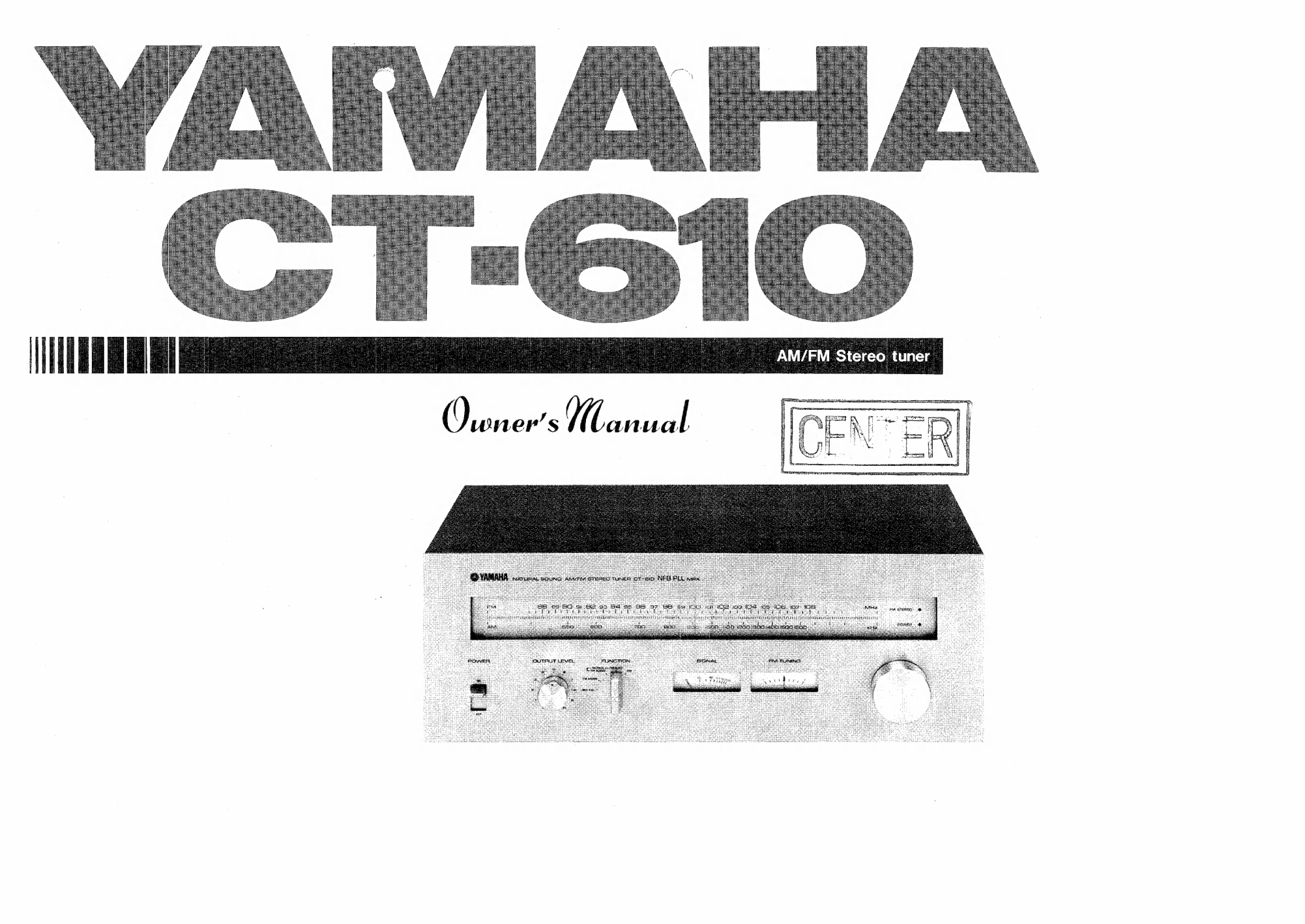
Yamaha CT-610 User manual
Other Yamaha Tuner manuals

Yamaha
Yamaha T-960II User manual

Yamaha
Yamaha CT-600 User manual

Yamaha
Yamaha T-32 User manual

Yamaha
Yamaha TX-500U User manual

Yamaha
Yamaha TX-930 User manual

Yamaha
Yamaha TD-38L User manual

Yamaha
Yamaha TX-590RDS User manual

Yamaha
Yamaha T-60 User manual

Yamaha
Yamaha YT-1100 User manual

Yamaha
Yamaha T-230 User manual

Yamaha
Yamaha TX-950 User manual

Yamaha
Yamaha YT-3000 User manual

Yamaha
Yamaha YT-140 User manual

Yamaha
Yamaha YT-150 User manual

Yamaha
Yamaha T-700 User manual

Yamaha
Yamaha TX-930 RS User manual

Yamaha
Yamaha TX-396L User manual

Yamaha
Yamaha T-09 User manual

Yamaha
Yamaha TX-497 User manual

Yamaha
Yamaha T-60 User manual


Popular Tuner manuals by other brands


MFJ
MFJ MFJ-928 instruction manual

NAD
NAD C 445 owner's manual

Sony
Sony ST-SA5ES operating instructions

Sirius Satellite Radio
Sirius Satellite Radio SC-FM1 user guide

Antique Automobile Radio
Antique Automobile Radio 283501B Installation and operating instructions

Monacor
Monacor PA-1200R instruction manual