Yamamoto Electric Works Manostar EMT1 User manual

R
I
N
1
-
R
EAD THE
I
NST
R
MAN
O
-
2-3,Nishi-sh
i
TEL. +8
I
NSTRUCT
R
UCT
O
STA
R
E
No. T
R
i
riike-cho,Na
g
1(78)-631-
6
ION MAN
U
ION
R
TRA
N
E
MT1
-EMT1
-
g
ata-ku,Kobe
,
6
000 FAX. +
8
U
AL BEFO
R
MA
N
N
SMIT
T
-
E09
,
Hyogo 653-
0
8
1(78)-631-
6
R
E USING
N
UAL
T
ER
0
031 JAPAN
6
020
RoH
S
S

1
INTRODUCTION
Thank you very much for purchasing of 「MANOSTAR TRANSMITTER EMT1」.
△
!
Caution
To ensure your safety in using this instrument:
・Be sure to read the instruction manual carefully before using this instrument so that you can
use it properly.
Wrong use may result in failure of this instrument and lead to its damage and accident. This
manual should be kept in a proper place so that you can refer to it any time you need.
△
!Warning
・Do not apply the pressure to the instrument more than it can withstand.
The diaphragm and the retainer are broken and cause of injury or accident, etc. disaster if the pressure
exceeding withstanding pressure of the pressure receiving element is applied to the instrument. The case
body and the transparent cover of the instrument are broken and cause of injury or accident, etc. disaster
if the pressure exceeding withstanding pressure of the instrument body is applied to the instrument.
・Avoid using where instrument is exposed to many vibration and impact.
Using this instrument where intensified vibration and impact may be damaged instrument. It is expected
that gas leaks of instrument which harms a parson.
・Do not exceed rated surrounding temperature, humidity and altitude in use.
Using this instrument by exceeding rated surrounding temperature and humidity and altitude it may be
damaged and cause the accident.
・Do not disassemble or reconstruct your instrument.
It may void your warranty.
△
!Caution
・As to where to install and how to install the instrument, be sure to follow the instruction manual
provided so as to ensure a proper method.
・In case of not being installed in dry and well-kept clean locations, the instrument must be enclosed in
box.
・Do not use organic solvent for cleaning.
Use of organic solvent, such as thinner and benzene, to remove surface dirt and stain may cause
melting and cracking on the surface. To remove dirt and stain, be sure to wipe them off with a wet cloth
using diluted neutral cleanser.
・Wrong terminal connection
If the signal input and output terminals are connected to the power supply, the internal mechanism burns
out.
・Dropping the product.
Product is a precision instrument. If you drop the product, there is a possibility that the exterior, also the
interior mechanism damage.
・Removal of the piping
If you replace the old pipes, please do not pull the pipe with a strong force. There is a possibility that the
pipe cap is broken.

2
Ⅰ.OUTLINE DRAWING
EMT1A (drip-proof indoor-use type)
EMT1B (exposed terminal connection type)
Ⅱ.ELECTRONICS CIRCUIT BLOCK DIAGRAM
Two wires method
Four wires method
3
2
1
4-
+
-
+
Diaphragm
Piping
connector
Grounding
Piping
connector
Amplifying circuit Linearizer
Out put
circuit
Oscillation
circuit Current check terminal
(4 to 20mA DC)
4 to 20mA DC
Wave detection
circuit
Span set Zero set
(H)
(L)
E
External
connection
instrument
Power supply
DC 24 V
100
Panel cut size
4 × φ 5 holes
or 4 × M4 holes tapped
100
116
88
φ7
115
55
32
91
116 ± 0.3
88 ± 0.3
4 × φ 5 installation long holes
G 1/2 internal thread
Panel cut size
4 × φ 5 holes
or 4 × M4 holes tapped
M4 terminal screws
φ7
4 × φ 5 installation long holes
94
88
100
100
116
55
32
116 ± 0.3
88 ± 0.3
3
2
1
4-
+
PT
Wave detection
circuit
Diaphragm
Piping
connector
Piping
connector
Amplifying circuit Linearizer
Out put
circuit
Oscillation
circuit 100V AC 50/60Hz
power supply input
Span se
t
Zero set
(H)
(L)
E
4 to 20mA DC
0 to 1mA DC
0 to 5V DC
1 to 5V DC
Power supply
circuit
Grounding
External
connection
instrument
No power
supply needed
for transmitter

3
Ⅲ.EXTERNAL CONNECTION DIAGRAM
・Two wires method transmitter receives 24V DC power
supply from outside and using power supply wiring,
transmits 4 to 20mA DC signal to external receiver units.
Note : Our receiver is equipped with AC-DC power supply
circuit for two wires method our transmitter,
therefore, In using combination with our receiver,
there is no need of the AC-DC power supply which
is separately available.
・Two wires method transmitter can monitor output signal
during operation, if they are connected with ampere
meter with internal resistance of less than 10Ω to check
terminal.
・Be careful about connection of two wires method
transmitter and four wires method transmitter as see
figures they are reverse in terms of current flow.
・Four wires method transmitter, which receives 100V AC
power supply, generates 24V DC inside transmitter to
work transmitting output signal to external receives.
Transmission output diagram (differential pressure - output signal)
Ⅳ.INSTALLATION AND TRIAL RUNNING
1.Installation
・Install this instrument at horizontal position (inclination angle at 5 °). If installation surface is vertical,
use the installation bracket on vertical wall to install horizontally. (refer to p.7)
・Take the space of 0.5 m above the transmitter for the purpose of adjustment and maintenance.
・Do not install the instrument outdoors directly. If you need to get it installed outdoors directly, store the
instrument at the storage casing with dew-proof construction.
・Avoid using where the instrument is subject to vibration, big impact and high humidity.
・Do not use at the place where corrosive gas (such as sulfuric gas and ammonia gas etc.) is present.
・Try to use the instrument away as far as possible from intensified power source and the unit generating
high frequency (high frequency welder and high frequency sewing machine etc.).
・The instrument is not designed for measurement of combustible gas and installation where explosive
danger risk area (hazardous area) exists. For flammable gas, be sure to provide by intrinsically-safe
system (EMT1H S).
Two wires method
Four wires method
0
4mA(1V)
12mA(3V)
20mA(5V)
0 50 100 -50 0 +50
(mA)
Pressure (
%FS)
For single pressure range For zero center range
Output signal
Pressure (%FS)
Output signal
(mA)
0mA(0V)
0.5mA(2.5V)
1mA(5V)
0 50 100 -50 0 +50
For single pressure range For zero center range
EMT 1
4 to 20 mA
1
2
4
3
Check terminal
from 4 to 20 mA
Grounding
Power supply DC 24 V
Receiving
equipment
4 to 20 mA
0 to 1 mA DC
0 to 5 V DC
0 to 5 V DC
EMT 1
1
2
4
3
Grounding
Receiving
equipmen
t
Power supply
AC 100 V 50 / 60 HZ

2.Con
VT
Th
e
tub
e
or
m
mo
r
pre
s
whe
hig
h
M
T
Thi
s
(O.
D
△
C
a
nectors an
d
connector f
o
[inst
a
e
se are conne
c
e
s. Be sure t
o
m
ore. Howev
e
r
e wall thickn
e
s
sure (includi
n
e
n the instru
m
h
er more tha
n
T
W connecto
r
s
t
s
is connector
D
. 6, the tole
r
△
!
a
ution
Tigh
t
torq
u
Do
n
than
dam
a
d
piping
o
r vinyl or pla
s
a
lled at EMT1
Pro
d
c
tors for vin
y
o
use I.D. 6
a
e
r, the vinyl
o
e
ss) with eno
u
n
g vacuum p
r
m
ent range or
n
50 kPa.
r
(double ring
t
eel made [ o
p
Product
can be conne
c
r
ance ± 0.1).
t
en the termin
a
u
e of 1.2 N・m.
n
ot apply exce
s
necessary, ot
h
a
ge the instru
m
s
tic tube, resi
n
FV type]
d
uct code:KG
y
l, plastic or
r
nd thickness
o
r plastic tub
e
u
gh withstan
d
r
essure) is re
q
the line pres
s
joint type) s
t
p
tion ]
code:KGAT1
M
c
ted to stainl
e
a
l screws with
s
sive torque m
o
h
erwise it will
m
ent body.
4
n-made
G
AT1VT
r
ubber
of 1 mm
e
(2 or
d
ing
q
uired
sure is
t
ainless
M
TW-S
e
ss tube
the
o
re
MT
c
This conn
made fro
m
the tolera
n
In case of
connecto
r
When thi
s
tube (O.
D
sleeve an
d
× 4) that
You need
I.D. 4) to
t
(Fig.Ⅲ-2)
c
onnector for
m
[installed a
t
e
ctor can be
m
copper, alu
m
n
ce ± 0.1, ri
n
connecting
w
r
.
connector i
s
D
. 6, I.D. 4),
r
d
use the resi
n
is the optio
n
Inner sleeve
t
his to conne
c
t
he connector
s
I
n
metal tube, b
r
t
EMT1FM ty
Product c
connected t
o
m
inum and so
n
g joint type)
w
ith stainless
t
s
connected t
o
r
emove the b
r
nous inner sl
e
n
al accessory
.
set [ option
]
Produc
c
t hard plastic
s
for metal tu
b
n
ner(resin
)
Sleeve(resin)
Plastic
t
r
ass-made
p
e]
ode:KGAT1V
T
o
the metal tu
b
on. (O.D. 6,
t
ube, use M
T
o
hard plasti
c
r
ass-made
e
eve set (XI
N
(Fig.Ⅲ-2)
]
t
code:XIN6X
4
tube (O.D. 6
,
b
e.(Fig.Ⅲ-2)
t
ube
T
b
e
T
W
c
N
6
4
,

5
3.Pressure of measurement and connection of piping
a) Measurement of positive pressure
Connect the tube to the high pressure side piping connector (indicated by red color or letter H).
The lower pressure port (blue or L) should opened to atmosphere, but do not remove the piping
connector.
b) Measurement of negative pressure
Connect the tube to the low pressure side piping connector (blue or L). The high pressure port (red or
H) should be opened to atmosphere, but do not remove the piping connector.
c) Measurement of differential pressure
Connect the tube from the high pressure piping connector to the high pressure port (red or H) and from
the low pressure piping connector to the low pressure port (blue or L).
△
!
Caution
Measurement of single pressure using an instrument with zero point center range.
Connect the tube to the high pressure side piping connector (red or H). In this case again,
leave the piping connector attached to the low pressure side, which is opened to atmosphere.
The single pressure is as displayed on a zero point center scale (+-).
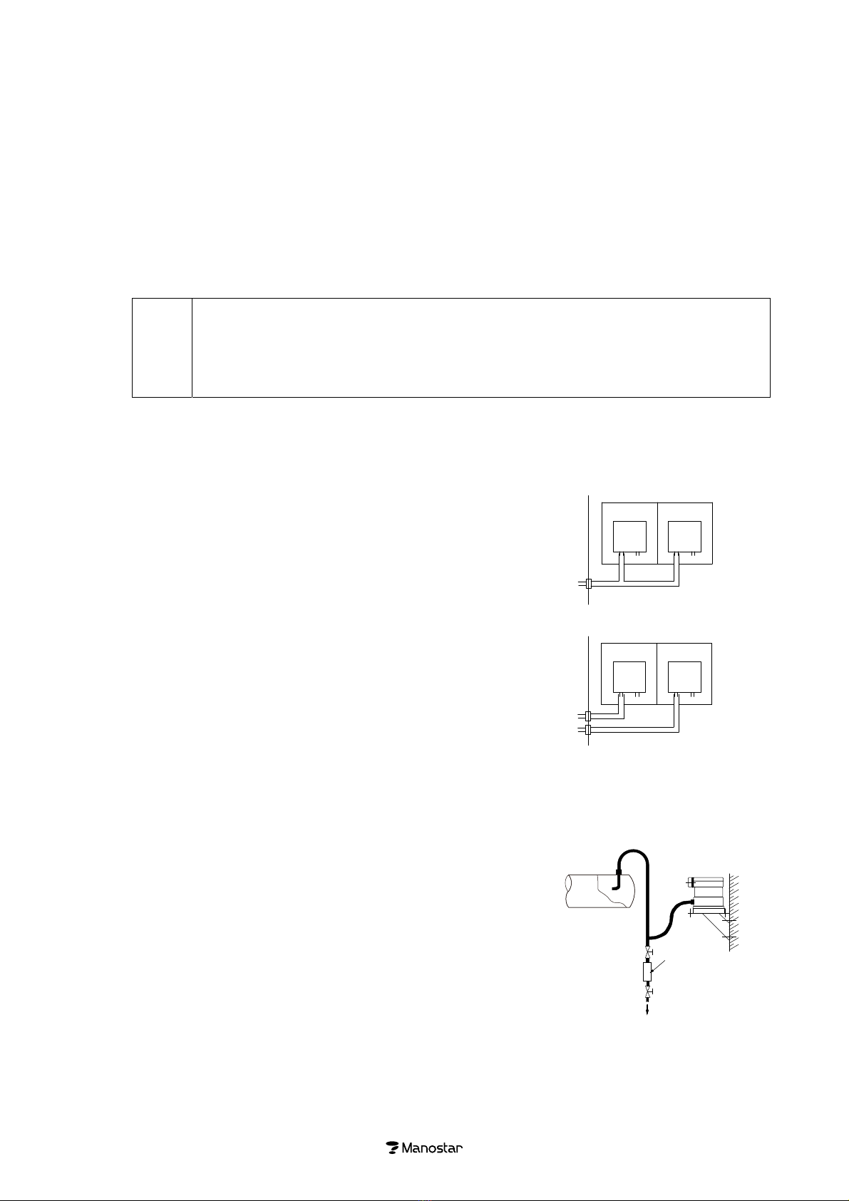
4.Caution of piping
・Prohibition of common piping
Piping each of pressure detectors and pressure receiving
instruments tube exclusively dedicated for it, and do not
connect the piping commonly with the adjacent system as
shown in the right figure.
Common piping causes measurement error because the
pressure of each system interferes.
・Prevention of clogged piping due to drain
If drain remains within the line, it causes measurement error.
Be sure to install the pressure receiving instrument above the
pressure outlet port of the pressure detector and arrange the
line so that the drain water should not remain in the slack
piping.
If the arrangement mentioned above in not possible, install a
drain tank within the line as shown in the right figure and clean
it once in a while.
After the cleaning of the tank, check that the air tightness is
fully kept.
・Measurement of high temperature gases
In the pressure measurement of high temperature gas, use the
pressure detector (pitot tube) made of the heat-proof metal
(such as stainless steel), and connect it with the pressure
receiving instrument through a metal tube which is long
enough to cool down the high temperature gas.
・Errors caused by long distance piping
The speed of response is delayed when the product is used for
remote monitoring.
In such application, the I.D. of the connection tube should be
as large as possible.
If the piping conditions of the high and low pressure side are
significantly different, the difference in the piping resistance
between high and low pressure side causes the difference in
pressure transmission time, and the measurement becomes
inaccurate.
Independent piping○
Passa
g
ewa
y
Passa
g
ewa
y
Room BRoom A
Room BRoom A
EMT1EMT1
EMT1EMT1
Common piping×
Drain
Drain
tank

6
5.Wiring and connection
・<EMT1A> can be used for cabling or conduit wiring. In addition, try to use wiring accessory or
connecting accessories that is separately available.
・Use shielded wire for input and output wiring on current and voltage signal, and do not put them near
power line. Moreover, do not let it go through the same conduit with power line.
・Use two core shielded wiring for four wires method cable and try to minimize the induction problems
coming from AC power supply of the same cable supply.
・Exercise care about terminal connection number because it is different according to types. Make sure
about a code of terminal connecting part on the terminal block, in accordance with the external
connection diagram.
・Use a crimping terminal suitable for M4 terminal screw. (refer to bellow the figure)
・Provide the the instrument on the grounding terminal with the class D grounding (grounding resistance
is 100 Ω or less).
Get grounding at the foot of installed unit. Also, EMT1A can get it from the grounding terminal inside
the upper cover.
・Make a one point grounding at the one end of shielded output signal cable.
△
!
Caution
Tighten the terminal screws with the torque of 1.0~1.3 N・m.
Do not apply excessive torque more than necessary, otherwise it will damage the instrument body.
6.Zero adjusting
1) Since zero point of the instrument is changed according to mounting posture, therefore, after installation of
horizontal posture is completed, be sure to perform zero adjustment.
2) After making sure that there is no mistake about wiring and connection, supply each equipment with power and
start a warm-up for 10 minutes.
3) Remove tubing of the instrument from High pressure side as well as Low pressure side and vent the
atmosphere.
4) Take out the upper cover of the instrument, turn the zero set adjuster inside and set zero point output of the
instrument at the value indicated on the table below.
5) As for span set adjusting, it has been adjusted already at our factory. Do not handle it.
Output signal table <EMT1A> <EMT1B>
For single
pressure range
For zero point
center range
Output signal
(DC) Zero point Zero point
4 to 20mA 4.0mA 12.0mA
0 to 1mA 0.0mA 0.5mA
0 to 5V 0.0V 2.5V
1 to 5V 1.0V 3.0V
φ9
φ8.2
φ4.3
E
Do not handle it.
Zero set
Printed circuit
bord
Do not handle it.
Zero set

Ⅴ.ACC
E
Fo
r
Pla
s
bus
h
Fo
r
For
If i
n
Ta
k
T
※
E
SSORY F
r
wirin
g
s
tic ground is
u
h
hold externa
l
r
wiring cond
u
installation br
n
stallation surf
a
k
e the space o
f
T
erminal cov
e
Adaptor f
o
※
Installation scr
e
OR PRES
S
Pla
s
u
sed to wiring
t
l
of cable as s
h
u
it
Inst
a
acket on verti
c
a
ce is vertical,
f
0.5 m above t
h
e
r set polyc
a
o
r conduit b
r
10
G 1/2
φ15
e
ws are not inclu
d
S
URE TR
A
s
tic ground(
fo
t
ransmitter wit
h
h
own right tabl
e
a
llation brack
e
c
al wall. Install
use the install
a
h
e transmitter
rbonate, bra
s
P
r
r
ass-made
[
Product code:
25
C19
Thread for
cable conduit
d
ed.
7
A
NSMITT
E
o
r EMT1A)
p
P
r
h
instrumentat
i
e
. Be carefully
e
t on vertical
this instrume
n
a
tion bracket
o
for the purpos
s
s-made [o
p
r
oduct code:
T
[
option]
ADPA-EMT1
22
110
135
φ
8×
φ
Manos
4×φ7 i
n
E
R
p
olyacetal-m
a
r
oduct code
R
AC4-2T
AC4-3T
AC4-4T
i
on cable. Cho
O.D. of cable
When y
o
19 or pl
tube, u
s
figure.
B
differ b
y
wall steel-
m
n
t at horizontal
o
n vertical wall
e of adjustmen
t
p
tion]
T
CA-T1
1.6
2555
100
12.5
135
30
5
installation holes
tar Transmitter
n
stallation holes on wall
a
de [option]
R
ubber bushin
g
color
Black
Red
Green
o
se the plastic
o
u wire the co
n
i
able metal co
n
s
e the adaptor
f
B
ecause wire i
n
y
internal threa
m
ade
[option
]
P
r
position (incli
n
to install hori
z
t
and mainten
a
0.5m or more
]
g
Applic
a
outer di
a
Min.
6.5
8.5
10.0
ground of the
n
duit tube of n
n
duit througho
u
for conduit as
n
let size of the
a
d of G 1 / 2.
]
r
oduct code:
B
n
ation angle at
z
ontally.
a
nce.
Vertical wall
a
ble cable
a
meter (mm)
Max.
9.0
11.0
12.5
size that rubb
e
o
rmal diamete
r
u
t the conduit
shown right
transmitter
B
RKT-T1GP1
5 °).
e
r
r

8
Ⅵ.PERIODIC INSPECTION
Generally speaking, it is important not to exert external stress to keep life and reliability of the instrument for a
long time.
Proper use of this instrument will ensure its faultless service over many years without any necessity of periodic
lubrication.
However, it is recommended that it is subjected to periodic inspection (calibration) once a year.
Ⅶ.PRODUCT WARRANTY
Warranty Period
This product warranty is valid for one year from the date of delivery to a place specified by an ordering party who
has transacted directly with Yamamoto Electric Works Co., Ltd.
Coverage
If a product breaks down due to a reason for which we are responsible during the warranty period and you return
the product to us, we will either repair or replace the product free of charge.
This warranty does not cover:
(1) Usage of the product under any inappropriate conditions or environment contrary to what is described in our
product catalog, specifications or manual.
Handling or usage of the product other than as described in our product catalog, specifications or manual.
(2) Breakdown due to a reason other than a fault within our product.
(3) Any product that has been modified or repaired by a party other than us.
(4) Any breakdown due to a reason that was not foreseeable based on scientific and technical standards applied
at the time of shipment.
(5) Any breakdown due to a reason not attributable to us such as a natural calamity or other disaster.
These terms of warranty represent our entire liability with respect to the product, and we shall have no liability
for any other loss arising in connection with a breakdown of the product.
*This product warranty is only valid within Japan.
This document is a translation from the original Japanese version, and the original Japanese version has priority
over this translation.
Be sure to refer to the original Japanese for the details of this warranty.
<Prior notice>
The specifications and description of the product explained in this instruction manual may be subject to
change without prior notice because of modification and the like.
Table of contents
Popular Transmitter manuals by other brands

Manta
Manta FMT002 user manual

Audiovox
Audiovox Prestige APS-2K4MS Programming guide

HomeAware
HomeAware HA360SSSC Installation and setup guide

Hama
Hama RTR-10 Operating instruction

Logic3
Logic3 MIP-165 instruction manual

Dwyer Instruments
Dwyer Instruments AVUL Series Installation and operating instructions

Lightware
Lightware HDMI-TPS-TX210 user manual

BWI Eagle
BWI Eagle AIR-EAGLE FM2 43-1000N4W-120VAC Product information bulletin

Ahlborn
Ahlborn ALMEMO 8390-1 Operating instruction

WIKA
WIKA GDT-20 operating instructions

Burkert
Burkert 8025 Series instruction manual

Emerson
Emerson Rosemount 2051 Wireless Series quick start guide