YAMIT AF-9800 Series User manual

Table of Contents
Subject Page No.
1.
Introduction
3
2.
Safety instructions
3
3.
Description
& Operation
4
4.
Technical
Data
6
5.
Initial Installation & Operation
8
6.
Maintenance & Periodical Checking
10
6.1
Electric motor Removal & Installation
10
6.2
Solenoid Removal & Installation
11
6.3
DP indicator Removal & Installation
12
6.4
Hydraulic Piston Assembly Removal & Installation
13
6.5
Coarse Screen Removal & Installation
14
6.6
Fine Screen Assembly Removal & Installation
15
6.7
Dirt Collector
Removal & Installation
17
6.8
Periodical
Checking
19
7.
IPB
21
8.
Appendix
28
8.1
ELI 02 Controller & Electrical Wiring
28
8.2
Control Loops Drawing
Baccara AC
34
8.3
Control Loops Drawing
Galsol AC
35
9.
International Warranty
36
ALL RIGHTS RESERVED, THIS MANUAL AND THE INFORMATION CONTAINED ARE NOT
ALLOWED TO BE USED WITHOUT WRITTEN PERMISSION FROM YAMIT Filtration &
Water Treatment Ltd.
AF9800

3
1. Introduction
General
YAMIT Filtration & Water Treatment Ltd. (hereinafter YAMIT) congratulates you on
purchasing the new AF-9800 SERIES self-cleaning filter. This filter now joins the wide
family of filters produced and supplied by YAMIT or agriculture, municipal water and
sewage systems, and all types of industrial applications. All products manufactured by
YAMIT are easy to install, use and service and don’t require special skills to operate
them.
For operation and maintenance of the filter please follow the instructions in this
manual.
2. Safety Instructions
1. It is necessary to use a noise protection device while the filter is in operation.
2. In the model with 12V DC power supply use the device which is provided by
YAMIT or equivalent (with certifications and power rating).
3. Verify that the control panel is grounded. Also verify that the AC power cord is
connected to the control panel through 3 x 6A-fuse protector.
4. Verify that the filter housing is grounded to the appropriate location.
5. Confirm AC power disconnection prior to service.
6. Confirm filter draining prior to service.
7. Take precautions while lifting, transporting or installing the filter.
8. Installation and operation of the filter should be performed so as to avoid direct
water splashing on the control unit.
9. Confirm that filter weight, when full, meets the support construction
requirements.
10. Prior to installation confirm line pressure matches filter’s operational pressure.
11. During installation, use standard flanges and connections only.
12. Check that all filter flanges bolts are properly secured.
13. Please note, the filter enters a flushing mode automatically, without prior
warning.
14. Use original parts only, while servicing the filter.
15. No changes or modifications to the equipment are allowed.
16. Do not perform any maintenance activities other than those given in this manual.
AF9800

4
1. INLET
2. Coarse screen
3. Fine screen
4. Flushing valve
5. Hydraulic piston
6. Flushing chamber
7. Dirt collector
8. Suction nozzle
9. Electric motor
10. Outlet
3. Description & Operation
Filter Assembly General Description
The AF-9800 Hydro electric self-cleaning screen filter enables high quality
filtering at filtering degrees of 10-3000 micron from different types of fluid
sources such as sewage, reservoirs, rivers, lakes, and wells.
The AF-9800 SERIES filter contains the following parts:
Figure 1: filter assembly
AF9800

5
Filter Operation General Description
Filtration
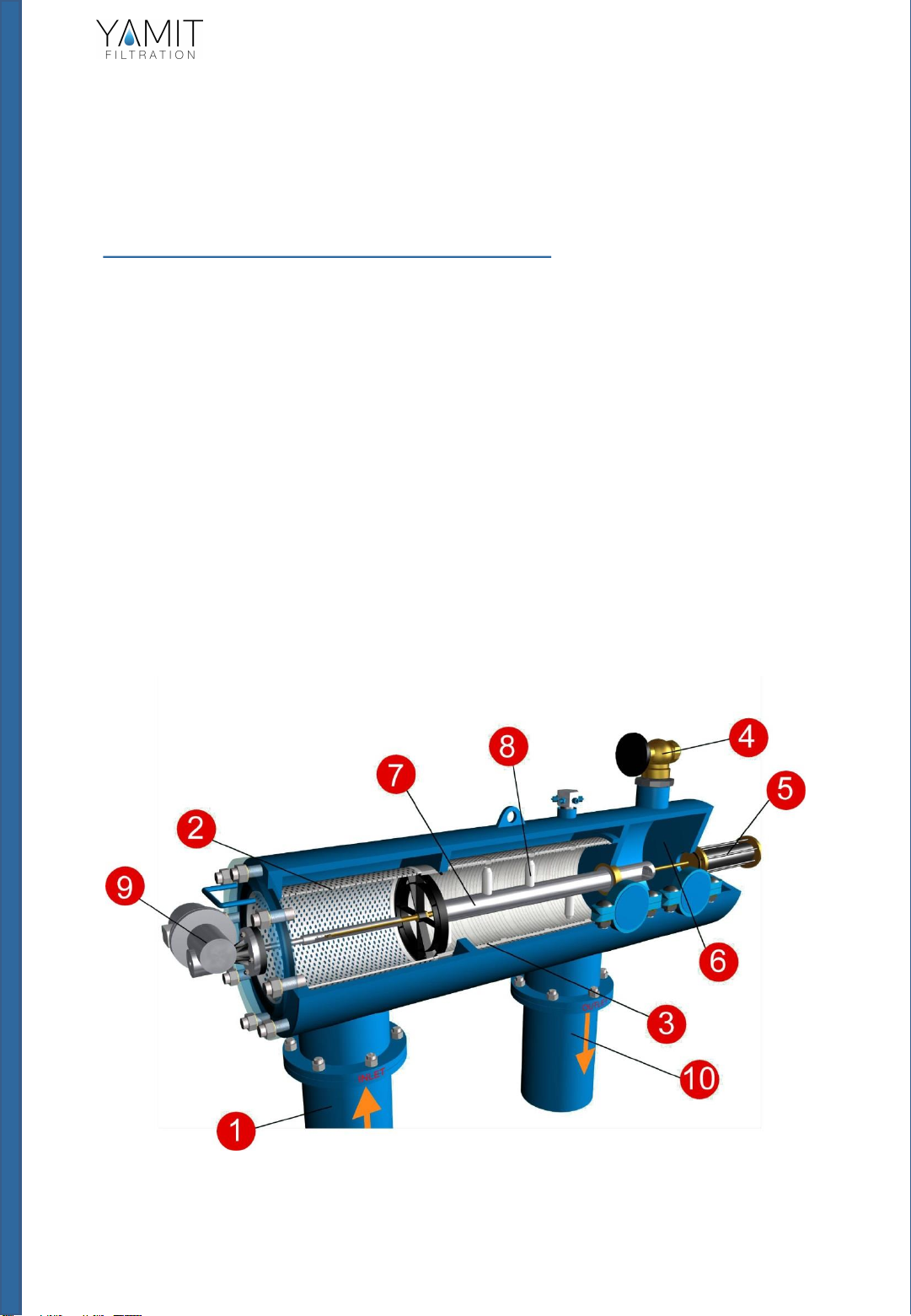
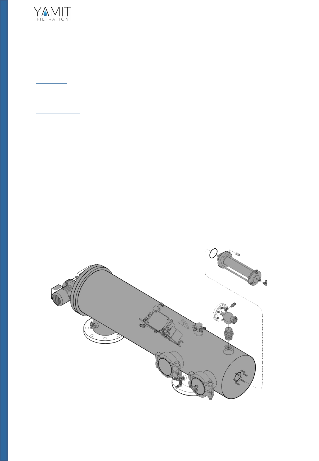
Water enters the filter through the “Inlet” (1) and passes through the coarse
screen (2) that functions as a “first stop” for rough particles. Water then
reaches the fine screen (3), which further purifies the flow by separating
smaller particles from the water. As more water flows through, impurities
build up on the fine screen. As impurities on the screen accumulate, a
pressure imbalance is built up between the internal section of the fine screen
(3) and its external section.
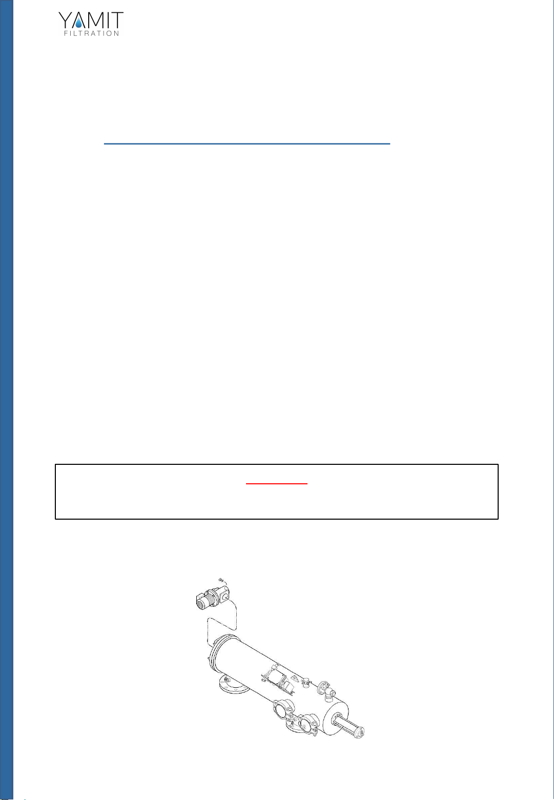
Cleaning Process
When the difference in pressure (ΔP) reaches the preset value on the
differential pressure indicator, Or when the preset time in the controller
arrives, a series of events is triggered while water continues to flow to the
system units. The controller transmits a signal for a 15 second flushing cycle.
The solenoid opens the flushing valve (4), and release the pressure from the
hydraulic piston (5). Water flows outside from the flushing valve (4). Pressure
in the hydraulic chamber (6) and the dirt collector (7) is significantly lowered
resulting in a suction process via the suction nozzles (8) to the dirt collector (7)
and from there to the hydraulic chamber (6) through the flushing valve (4)
outside. The electric motor (9) simultaneously rotates the dirt collector (7)
around its axis. The pressure is released from the piston (5) and the high
pressure inside the filter causes linear movement of the dirt collector. The
combination of the linear movement and rotation efficiently cleans the entire
internal screen (3) surface.
At the end of the 15 second cycle the flushing valve (4) closes and the
operation of the electric motor (9) is stopped. The increased water pressure
returns the hydraulic piston (5) to its initial position. The filter is now ready for
the next cycle, with clean and filtered water flowing through the “Outlet” (10).
The 15 second flushing cycle resumes operation whenever the difference in
pressure reaches the preset pressure value set on the differential pressure
indicator. Or when the preset time in the controller is triggered on. If the
pressure difference remains unchanged after one cycle, another cycle will start
after a delay of 10 seconds
AF9800

4. Technical Data
Standard Features
•Minimum operating pressure: 1.5 bar (21.8 psi)
•Maximum operating pressure: 10 bar (145 psi)
•Clean filter pressure loss: 0.1 (2 psi)
•Maximum water temperature: 65°C (149°F)
•Filtration range: 50-3000 micron
•Electric motor: 110V, 220V or 380-440V 3-phase, 0.5HPDC,
24V AC
•Flush water consumption
(at minimum working pressure): 80 liters (21 gallons)
•Filter housing materials: carbon steel coated w/baked on epoxy \
Measurements & Weight
Model
In/Out
D
(mm) (in)
D1
(in)
H
(mm) (in)
L
(mm) (in) L1
(mm) (in) L2
(mm) (in)
Shipping
Weight
(kg) (lb)
Packing Volume
LxWxH
(m) (ft)
AF9810X
250
10 16
720
28.35
1100
43.31
2787
109.72
3233
127.28
423
932
1.0x0.83x3.4
3.28x2.72x11.0
AF9812R
300
12 16
655
25.79
1100
43.31
2787
109.72
3233
127.28
428
944
1.0x0.83x3.4
3.28x2.72x11.0
AF9814R
350
14 18
770
30.31
1270
50.00
2787
109.72
3233
127.28
500
1102
1.0x0.83x3.4
3.28x2.72x11.0
AF9816R
400
16 18
770
30.31
1270
50.00
2787
109.72
3233
127.28
518
1142
1.0x0.83x3.4
3.28x2.72x11.0
AF9816X
400
16 24
925
36.42
1270
50.00
2787
109.72
3233
127.28
713
1572
1.2x0.98x3.4
3.94x3.22x11.0
6
R = Parallel X = Extra-long filter with extra-large filtration area
* Flow rate data is for high quality water at filtration grade of 120 microns.
** Flushing flow rate data is for minimum operational pressure (1 bars / 15 psi).
AF9800

7
Flow Rate
Micron
50 80 100
120
150
200
300
400
500
800
1000
1500
2000
3000
Mesh
300
200
150
120
100
80 55 40 30 20 15 10 85
7
Filtration Grade Conversion Table
Pressure Loss at 200 micron
Model
Int/Outlet
ØD
(mm) (in)
Max. Flow Rate
(m3/h) (gpm)
Screen area
(cm2) (in2)
Flushing
Flow rate
(m3/h) (gpm)
Flushing
Volume
(m³) (gal)
AF9810X
250
10
400 1760
8410
1304 30 132
0.0833
22.0
AF9812R
300
12
600 2640
11710
1815 30 132
0.0833
22.0
AF9814R
350
14
900 3960
12990
2013 30 132
0.0833
22.0
AF9816R
400
16
1100 4850
12990
2013 30 132
0.0833
22.0
AF9816X
400
16
1500 6600
17020
2638 30 132
0.0833
22.0
Head loss
AF9800

5. Initial Installation & Operation
General
The filter assembly is protectively packed with all parts assembled.
Installation
1. Take the filter assembly out of the wood platform.
2. Install the filter assembly to the inlet line and outlet line.
3. Connect a drainpipe to the hydraulic flushing valve outlet opening (at
least 63 mm or 2” diameter and no longer then 5m). Confirm that water
runs freely out of the drainpipe.
4. Position the control panel in such a way as to be protected against
humidity and solar radiation.
5. Connect the control panel to the power source.
6. Check that all connections are properly secured.
7. Check that all bolts and nuts on filter periphery are properly tightened
and secured.
8
Figure 2: Initial Filter Installation
AF9800

9
Initial Operation
1. Gradually open the inlet valve (make sure that the outlet valve, if
installed, is open).
2. Check the filter assembly and its connections for leaks.
3. Perform a flushing cycle by disconnecting the low pressure tube from the
differential pressure indicator (closing of the electrical circuit) –re
connect it immediately as flushing start.
4. Verify that the hydraulic flushing valve closes after 10 seconds.
5. Verify that the hydraulic piston fully extends during back flush.
6. When the filter is clean, verify that the differential pressure between
inlet and outlet does not exceed 0.1 bar.
7. Check that the differential pressure is set to 7 psi or 0.5 bar in the
controller (see appendix no 1).
8. Perform an additional flushing cycle manually by pushing the manual
bottom (M on the screen display). (See Figure 3).
AF9800

10
6. Maintenance & Periodical Checks
6.1 –Electric Motor Removal & Installation
1. Close the inlet and the outlet line valves.
2. Set the main switch at the control panel to "0" position.
3. Verify that filter is drained prior to service.
4. A qualified technician will carry out the electrical connections.
5. Disconnect the electric motor from the electrical power source. Prior to removal,
mark the electrical wiring connections (according to colors) on the new motor.
6. Remove the screw in the rear part of the motor.
7. Remove the four nuts and washers attaching the motor assembly to the filter
assembly.
8. Carefully remove the old motor assembly. Verify existence of splint on the motor
axis groove.
9. Remove the splint out of the old motor axis groove.
10. Carefully slide the new motor assembly into the filter assembly.
11. Install the splint into the new motor axis groove.
12. Install the four nuts and washers attaching the motor assembly to the filter
assembly and the screw to the rear part of the motor.
13. Connect the electric motor to the electrical power source according to the
marking previously made in step 5.
14. Set the main switch at the control panel to "1" position.
15. Open the inlet and the outlet line valves.
16. Perform a flushing cycle by pressing the MANUAL FLUSH switch at the control
panel.
17. Verify that the motor is spinning clockwise and the hydraulic flushing valves close
after 15 seconds.
18. Check for leaks.
WARNING
Take precautions while operating the filter as the filter may enter a flushing
mode automatically, without prior warning.
Figure 4: Electric Motor Removal & Installation
AF9800

11
6.2 - Solenoid Removal & Installation
The solenoid hydraulically controls the flushing valve's operation.
1. Remove the upper cover, disconnect and remove the 4 x 1.5V batteries.
2. Disconnect the solenoid control tubes.
3. Remove the fittings from the damaged solenoid.
4. Disconnect the 2 electrical wiring from the control card terminals.
5. Remove the nut from the solenoid lower section.
6. Pull the solenoid out of the control assembly.
7. Insert a new solenoid into the control assembly.
8. Install the nut on the solenoid lower section.
9. Install the fittings on the ports of the new solenoid.
10. Connect the 2 electrical wiring to the control card terminals (See Figure 5).
11. Connect the solenoid control tubes.
12. Connect the 4 X 1.5V batteries according to the correct polarity and close the
electronic control unit cover.
13. Perform a flushing cycle by disconnecting the low pressure tube from the
differential pressure indicator (closing of the electrical circuit) –re-connect it
immediately as flushing starts.
14. Verify that the hydraulic flushing valve closes after 10 seconds.
15. Perform an additional flushing cycle manually by pushing the manual bottom (M
on the screen display). (See Figure 3)
Figure 5: Solenoid Removal & Installation
WARNING
Take precautions while operating the filter as the filter may enter a flushing
mode automatically, without prior warning.
AF9800

6.3 –DP Indicator Removal & Installation
The differential pressure indicator supplies data to the electronic control unit, which
controls the filter's self-cleaning process.
1. Set the main switch at the control panel to "0" position.
2. Close the inlet and outlet valves of the filter and verify that filter is drained prior
to service.
3. Disconnect the two control tubes from the differential pressure indicator.
4. Remove the 4 screws attaching the electric connection box.
5. Disconnect the electrical wiring from the electric terminal in the connection box.
6. Remove the two nuts located at the bottom of the electronic control unit
assembly and remove the screws.
7. Pull the differential pressure indicator out of the control assembly.
8. Insert a new differential pressure indicator into the control assembly.
9. Install the two screws and nuts at the bottom of the electronic control unit
assembly.
10. Connect the two control tubes to the differential pressure indicator [note that the
high pressure and the low pressure connected to the right fittings.
11. Connect the electrical wiring to terminals D and P on the electric terminal
connection box.
12. Set the main switch at the control panel to "1" position.
13. Perform a flushing cycle by disconnecting the low pressure tube from the
differential pressure indicator (closing of the electrical circuit) –re-connect it
immediately as flushing start.
14. Verify that the hydraulic flushing valve closes after 15 seconds.
15. Perform a flushing cycle by pressing the MANUAL FLUSH switch at the control
panel.
12
Figure 6: DP Indicator Removal & Installation
WARNING
Take precautions while operating the filter as the filter may enter a flushing
mode automatically, without prior warning.
AF9800

13
6.4 –Hydraulic Piston Assembly Removal & Installation
The hydraulic piston enables the linear movement of the dirt collector.
1. Set the main switch at the control panel to "0" position.
2. Close the inlet and outlet valves of the filter and verify that filter is rained
prior to service.
3. Disconnect the control tube from the piston assembly aft section.
4. Remove the six nuts and washers connecting the piston assembly to the
filter housing.
5. Carefully remove the piston assembly.
6. Remove the seal from the old piston assembly forward section.
7. Position the forward seal into the new piston assembly.
8. Lubricate forward seal with silicon grease.
9. Carefully slide the new piston assembly into the filter housing.
10. Install the six nuts and washers connecting the piston assembly to the
filter housing.
11. Connect the control tube to the piston assembly aft section.
12. Set the main switch at the control panel to "1" position.
13. Open the inlet and the outlet line valves.
14. Check for leaks.
15. Perform a flushing cycle by disconnecting the low pressure tube from the
differential pressure indicator (closing of the electrical circuit) –re-
connect it immediately as flushing start.
16. Verify that the hydraulic flushing valve closes after 15 seconds.
17. Perform a flushing cycle by pressing the MANUAL FLUSH switch at the
control panel.
Figure 7: Retrait et installation du vérin hydraulique
WARNING
Take precautions while operating the filter as the filter may enter a flushing
mode automatically, without prior warning.
AF9800

6.5 - Coarse Screen Removal & Installation
1. Close the inlet and the outlet line valves.
2. Set the main switch at the control panel to "0" position.
3. Verify that filter is drained prior to service.
4. Remove the nuts and washers attaching the cover to the filter housing.
5. Remove the cover with the motor assembly and the motor’s dirt collector axis
housing.
6. Remove the body seal from the cover groove.
7. Pull the old coarse screen out of the fine screen assembly
8. Slide the new coarse screen into the fine screen assembly.
9. Verify that the straight side of the body seal fits into the groove located in the
cover.
10. Put the cover into it’s place on the filter. (Take care that the motor’s dirt collector
axis housing is slide on the dirt collector axis).
11. Install the nuts and washers attaching the cover to the filter housing.
12. Set the main switch at the control panel to "1" position.
13. Open the inlet and outlet line valves.
14. Perform a flushing cycle by pressing the MANUAL FLUSH switch at the control
panel.
15. Check for leaks.
14
Figure 8: Coarse Screen Removal & Installation
WARNING
Take precautions while operating the filter as the filter may enter a flushing
mode automatically, without prior warning.
Cover
O-Ring
Coarse Screen
AF9800

15
6.6 - Fine Screen Assembly Removal & Installatione
1. Close the inlet and the outlet line valves.
2. Set the main switch at the control panel to "0" position.
3. Verify that filter is drained prior to service.
4. Remove the nuts and washers attaching the cover to the filter housing.
5. Remove the cover with the motor assembly.
6. Remove the body seal from the cover groove.
7. Pull the coarse screen out of the fine screen assembly
8. Unscrew the leading screw from the end of the dirt collector axis.
9. Pull the old fine screen assembly with the dirt collector out of the filter housing
assembly
10. Remove the dirt collector form the fine screen.
11. Remove the seals from the old fine screen assembly.
12. Position both upper and lower seals into the new fine screen assembly.
13. Lubricate upper and lower seals with silicon grease.
14. Slide the dirt collector into the new fine screen.
15. Install the screw on the top of the dirt collector axis.
16. Slide the new fine screen assembly with the dirt collector into the filter housing
assembly.
17. Slide the coarse screen into the fine screen assembly.
18. Verify that the straight side of the body seal fits into the groove located in the
cover.
19. Put the cover into it’s place on the filter. (Take care that the motor’s dirt collector
axis housing is slide on the dirt collector axis)
20. Install the nuts and washers attaching the cover to the filter housing.
21. Set the main switch at the control panel to "1" position.
22. Open the inlet and outlet line valves.
23. Perform a flushing cycle by pressing the MANUAL FLUSH switch at the control
panel.
24. Check for leaks.
WARNING
Take precautions while operating the filter as the filter may enter a flushing
mode automatically, without prior warning.
AF9800

16
Figure 9: Fine Screen Assembly Removal & Installation
AF9800

17
6.7 - Dirt Collector Removal & Installation
1. Close the inlet and the outlet line valves.
2. Set the main switch at the control panel to "0" position.
3. Verify that filter is drained prior to service.
4. Remove the nuts and washers attaching the cover to the filter housing.
5. Remove the cover with the motor assembly.
6. Remove the body seal from the cover groove.
7. Pull the coarse screen out of the fine screen assembly
8. Unscrew the screw from the end of the dirt collector axis.
9. Pull the fine screen assembly with the dirt collector out of the filter housing
assembly
10. Remove the old dirt collector form the fine screen.
11. Lubricate upper and lower seals with silicon grease.
12. Slide the new dirt collector into the new fine screen.
13. Install the screw on the top of the dirt collector axis.
14. Slide the fine screen assembly with the new dirt collector into the filter housing
assembly.
15. Slide the coarse screen into the fine screen assembly.
16. Verify that the straight side of the body seal fits into the groove located in the
cover.
17. Put the cover into it’s place on the filter. (Take care that the motor’s dirt collector
axis housing is slide on the dirt collector axis).
18. Install the nuts and washers attaching the cover to the filter housing.
19. Set the main switch at the control panel to "1" position.
20. Open the inlet and outlet line valves.
21. Perform a flushing cycle by pressing the MANUAL FLUSH switch at the control
panel.
22. Check for leaks.
WARNING
Take precautions while operating the filter as the filter may enter a flushing
mode automatically, without prior warning.
AF9800

18
Figure 10: Dirt Collector Removal & Installation
AF9800

19
6.8 - Periodical Checks
Perform yearly Periodical Checks at the beginning of the season, according to the
following instructions:
1. Check the condition of the coarse screen. If defective, replace according to
"Coarse Screen Removal & Installation".
2. Check the condition of the fine screen assembly. If defective, replace according to
"Fine Screen Assembly Removal & Installation".
3. Check seals condition. Lubricate with silicon grease.
4. Remove the dirt collector according to "Dirt Collector Removal & Installation" and
check the dirt collector suction nozzles height (see table). If defective, screw out
the nozzle and replace with a new one.
5. Check condition of the bearings, replace if damaged or deformed.
6. Remove the Piston according to “piston removal & installation” check its
condition, clean it from sediments and replace seals if required.
7. Check existence of grease on the motor axis.
8. Check the filter housing for paint damage and corrosion. If required, clean area
with sandpaper and apply a thin layer of basic + epoxy paint.
9. Check for leaks.
Dirt Collector Suction Nozzles Height Table
Type Number X(Nozzle Height)
AF9803LOPR 71 mm
AF980/6/8 /10 LOPR 63 mm
AF9800

20
Figure 10: Periodical Checks
AF9800
This manual suits for next models
5
Table of contents
Other YAMIT Water Filtration System manuals
Popular Water Filtration System manuals by other brands

Pentair
Pentair OMNIFILTER IN-FF-500-SG-QC-4 Installation and operation manual

Whirlpool
Whirlpool classic 65 Use and care guide

AquaMaster
AquaMaster AMS700 Owner's manual and installation guide

3B Filters
3B Filters 8600 Series Service instructions

Dometic
Dometic RO400 User instructions

Plasma Made
Plasma Made GUC 1212 Installation and user manual