3
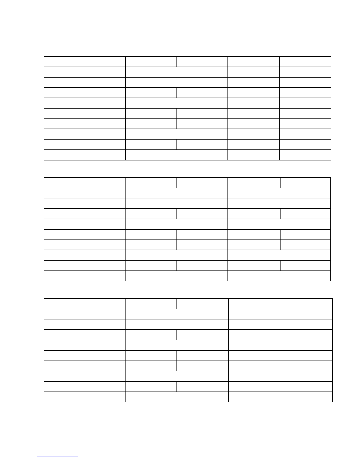
Model & Parameter List
Model FD2.1-200-8L FD2.1-200-8H FD2.5-300-8L FD2.5-300-8H
Rated power(W) 200W 300W 300W
Rated voltage (V) 24 24V 24V
Rotor diameter(M) 2.2 1.8 2.5 2.0
Start-up wind speed(m/s) 3 2.5 2.5
Rated wind speed(m/s)6 12 7 12
Security wind speed(m/s) 16 35 16 35
Rated rotating rate(r/m)450 400 400
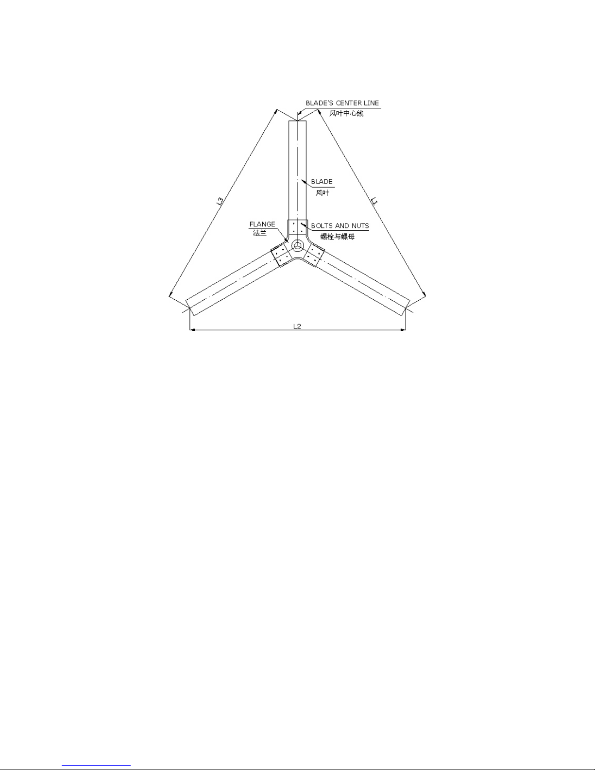
Blade material glass fiber glass fiber glass fiber Glass fiber
Blade quantity 3 3 3
Model FD2.7-500-10L FD2.7-500-10H FD3.0-1000-10L FD3.0-1000-10H
Rated power(W) 500W 1KW
Rated voltage (V) 24 48
Rotor diameter(M) 2.5 2.1 2.7 2.3
Start-up wind speed(m/s) 2 2
Rated wind speed(m/s)8 12 9 12
Security wind speed(m/s) 16 35 16 35
Rated rotating rate(r/m)400 400
Blade material glass fiber glass fiber glass fiber glass fiber
Blade quantity 3 3
Model FD3.6-2000-10L FD3.6-2000-10H FD5.0-3000-16L FD5.0-3000-16H
Rated power(W) 2000W 3000W
Rated voltage (V) 120 240
Rotor diameter(M) 3.2 2.5 4.5 3.6
Start-up wind speed(m/s) 2 2
Rated wind speed(m/s)9 12 10 12
Security wind speed(m/s) 16 35 25 45
Rated rotating rate(r/m)400 220
Blade material glass fiber glass fiber glass fiber glass fiber
Blade quantity 3 3