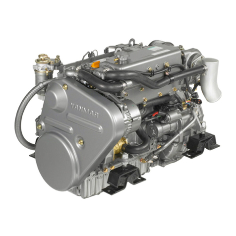
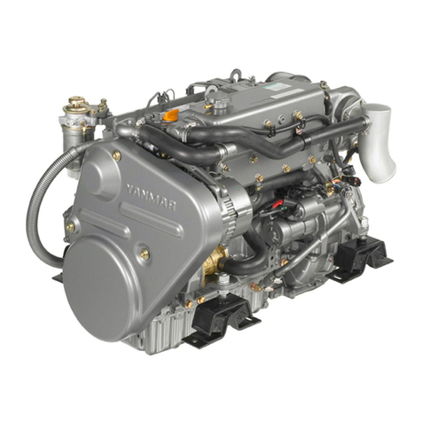
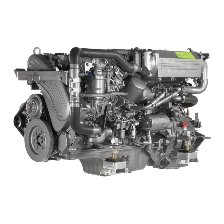
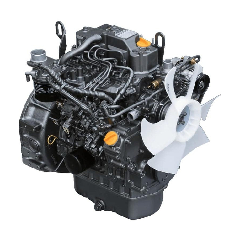
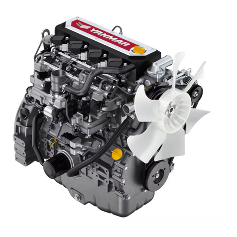
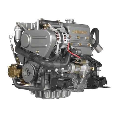
Yanmar 4JH3-TE User manual

OPERATION MANUAL
Be sure to read this manual for safe and
proper operation.
Store this manual carefully after use.

Thank you for purchasing a Yanmar Marine Diesel Engine.
[ INTRODUCTION ]
• This Operation Manual describes the operation, maintenance and inspection, and han-
dling precautions for the
4JH3-TE/-TCE/-HTE/-DTE
Yanmar Marine Diesel Engine.
1. FOR SAFE OPERATION :
Safety indications, safety precautions, explanation and use.
2. EXPLANATION OF PRODUCT :
Specifications for this series and basic operation principles.
3.
PREPARATION FOR OPERATION
: Fuel oil, lube oil, cooling water, etc. check and supply.
4. OPERATION :
Starting, speed adjusting, stopping and long-term storage.
5. MAINTENANCE & INSPECTION: Periodic inspection, inspection items and time period,
and detailed explanation.
6.
TROUBLE AND TROUBLESHOOTING
: Simple troubles and table of troubleshooting meaures.
• Read this Operation Manual carefully before operating the engine to ensure that it is
used correctly and that it stays in the best possible condition.
• Keep this Operation Manual in a convenient place for easy access.
• If this Operation Manual is lost or damaged, order a new one from your dealer or dis-
tributor.
• If giving your engine to someone else, be sure to attach this Operation Manual.
• Constant efforts are made to improve the quality and performance of Yanmar prod-
ucts, so some details included in this Operation Manual may differ slightly from your
engine. If you have any questions about this, please contact your Yanmar dealer or
distributor.
California
Proposition 65 Warning
Diesel engine exhaust and some of its
constitutions are known to the State of
California to cause cancer, birth defects,
and other reproductive harm.
California
Proposition 65 Warning
Battery posts, terminals,and related
accessories contain lead and lead
compounds, chemicals knouw to the
State of California to cause cancer
and reproductive harm.

INDEX page No.
1 FOR SAFE OPERATION . . . . . . . . . . . . . . . . . . . . . . . . . . . . . . . . . . . . . . . . . . . . . . . . .1
1.1 Warning Symbols . . . . . . . . . . . . . . . . . . . . . . . . . . . . . . . . . . . . . . . . . . . . . . . . . . . . . . . . . . . . . . . . . 1
1.2 Safety Precautions . . . . . . . . . . . . . . . . . . . . . . . . . . . . . . . . . . . . . . . . . . . . . . . . . . . . . . . . . . . . . . . . 2
1.3 Location of Product Safety Labels . . . . . . . . . . . . . . . . . . . . . . . . . . . . . . . . . . . . . . . . . . . . . . . . . . . . 4
2 PRODUCT EXPLANATION . . . . . . . . . . . . . . . . . . . . . . . . . . . . . . . . . . . . . . . . . . . . . . .5
2.1 Use & Driving System . . . . . . . . . . . . . . . . . . . . . . . . . . . . . . . . . . . . . . . . . . . . . . . . . . . . . . . . . . . . . 5
2.2 Engine Specifications . . . . . . . . . . . . . . . . . . . . . . . . . . . . . . . . . . . . . . . . . . . . . . . . . . . . . . . . . . . . . . 6
2.2.1 4JH3-TE . . . . . . . . . . . . . . . . . . . . . . . . . . . . . . . . . . . . . . . . . . . . . . . . . . . . . . . . . . . . . . . . . . . . . . . . 6
2.2.2 4JH3-TCE . . . . . . . . . . . . . . . . . . . . . . . . . . . . . . . . . . . . . . . . . . . . . . . . . . . . . . . . . . . . . . . . . . . . . . . 7
2.2.3 4JH3-HTE . . . . . . . . . . . . . . . . . . . . . . . . . . . . . . . . . . . . . . . . . . . . . . . . . . . . . . . . . . . . . . . . . . . . . . . 8
2.2.4 4JH3-DTE . . . . . . . . . . . . . . . . . . . . . . . . . . . . . . . . . . . . . . . . . . . . . . . . . . . . . . . . . . . . . . . . . . . . . . . 9
2.3 Names of Parts . . . . . . . . . . . . . . . . . . . . . . . . . . . . . . . . . . . . . . . . . . . . . . . . . . . . . . . . . . . . . . . . . 10
2.4 Major Servicing Parts . . . . . . . . . . . . . . . . . . . . . . . . . . . . . . . . . . . . . . . . . . . . . . . . . . . . . . . . . . . . . 11
2.5 Operation Equipment . . . . . . . . . . . . . . . . . . . . . . . . . . . . . . . . . . . . . . . . . . . . . . . . . . . . . . . . . . . . . 12
2.5.1 Instrument Panel . . . . . . . . . . . . . . . . . . . . . . . . . . . . . . . . . . . . . . . . . . . . . . . . . . . . . . . . . . . . . . . . . 12
2.5.2 Remote Control Handle . . . . . . . . . . . . . . . . . . . . . . . . . . . . . . . . . . . . . . . . . . . . . . . . . . . . . . . . . . . . 15
3 BEFORE OPERATION . . . . . . . . . . . . . . . . . . . . . . . . . . . . . . . . . . . . . . . . . . . . . . . . .18
3.1 Fuel Oil, Lube Oil and Cooling Water . . . . . . . . . . . . . . . . . . . . . . . . . . . . . . . . . . . . . . . . . . . . . . . . 18
3.1.1 Fuel Oil . . . . . . . . . . . . . . . . . . . . . . . . . . . . . . . . . . . . . . . . . . . . . . . . . . . . . . . . . . . . . . . . . . . . . . . . 18
3.1.2 Lube oil . . . . . . . . . . . . . . . . . . . . . . . . . . . . . . . . . . . . . . . . . . . . . . . . . . . . . . . . . . . . . . . . . . . . . . . . 19
3.1.3 Cooling Water . . . . . . . . . . . . . . . . . . . . . . . . . . . . . . . . . . . . . . . . . . . . . . . . . . . . . . . . . . . . . . . . . . . 19
3.2 Supplying Fuel . . . . . . . . . . . . . . . . . . . . . . . . . . . . . . . . . . . . . . . . . . . . . . . . . . . . . . . . . . . . . . . . . . 20
3.2.1 Filling the Fuel Tank . . . . . . . . . . . . . . . . . . . . . . . . . . . . . . . . . . . . . . . . . . . . . . . . . . . . . . . . . . . . . . 20
3.2.2 Bleeding the Fuel System . . . . . . . . . . . . . . . . . . . . . . . . . . . . . . . . . . . . . . . . . . . . . . . . . . . . . . . . . . 20
3.3 Supplying Engine Lube Oil . . . . . . . . . . . . . . . . . . . . . . . . . . . . . . . . . . . . . . . . . . . . . . . . . . . . . . . . . 21
3.4 Supplying Marine Gear Lube Oil . . . . . . . . . . . . . . . . . . . . . . . . . . . . . . . . . . . . . . . . . . . . . . . . . . . . 21
3.5 Supplying Cooling Water . . . . . . . . . . . . . . . . . . . . . . . . . . . . . . . . . . . . . . . . . . . . . . . . . . . . . . . . . . 22
3.6 Cranking . . . . . . . . . . . . . . . . . . . . . . . . . . . . . . . . . . . . . . . . . . . . . . . . . . . . . . . . . . . . . . . . . . . . . . . 23
3.7 Checking the Lube Oil and Cooling Water . . . . . . . . . . . . . . . . . . . . . . . . . . . . . . . . . . . . . . . . . . . . . 23
4 HOW TO OPERATE . . . . . . . . . . . . . . . . . . . . . . . . . . . . . . . . . . . . . . . . . . . . . . . . . . .24
4.1 Inspection Before Starting . . . . . . . . . . . . . . . . . . . . . . . . . . . . . . . . . . . . . . . . . . . . . . . . . . . . . . . . . 24
4.2 Checking the Illumination Lamps of the Panel Meters . . . . . . . . . . . . . . . . . . . . . . . . . . . . . . . . . . . . 26
4.2.1 Checking the Illumination Lamps of the Panel Meters . . . . . . . . . . . . . . . . . . . . . . . . . . . . . . . . . . . . 26
4.2.2 Checking the Alarm Devices . . . . . . . . . . . . . . . . . . . . . . . . . . . . . . . . . . . . . . . . . . . . . . . . . . . . . . . . 26
4.2.3 Checking the Panel Meters . . . . . . . . . . . . . . . . . . . . . . . . . . . . . . . . . . . . . . . . . . . . . . . . . . . . . . . . . 26
4.3 starting . . . . . . . . . . . . . . . . . . . . . . . . . . . . . . . . . . . . . . . . . . . . . . . . . . . . . . . . . . . . . . . . . . . . . . . . 27
4.3.1 Daily Starting . . . . . . . . . . . . . . . . . . . . . . . . . . . . . . . . . . . . . . . . . . . . . . . . . . . . . . . . . . . . . . . . . . . . 27
4.3.2 Starting Under Low Temperature Conditions . . . . . . . . . . . . . . . . . . . . . . . . . . . . . . . . . . . . . . . . . . . 27
4.3.3 Restarting After Starting Failure . . . . . . . . . . . . . . . . . . . . . . . . . . . . . . . . . . . . . . . . . . . . . . . . . . . . . 27
4.3.4 After the Engine has Started . . . . . . . . . . . . . . . . . . . . . . . . . . . . . . . . . . . . . . . . . . . . . . . . . . . . . . . . 28
4.4 Adjusting the Engine Speed . . . . . . . . . . . . . . . . . . . . . . . . . . . . . . . . . . . . . . . . . . . . . . . . . . . . . . . . 28
4.5 Clutch Operation for the Marine Gear . . . . . . . . . . . . . . . . . . . . . . . . . . . . . . . . . . . . . . . . . . . . . . . . 29
4.5.1 Forward, Neutral, Reverse . . . . . . . . . . . . . . . . . . . . . . . . . . . . . . . . . . . . . . . . . . . . . . . . . . . . . . . . . 29
4.5.2 Switching to Trawling (Available for KMH4A only) . . . . . . . . . . . . . . . . . . . . . . . . . . . . . . . . . . . . . . . 29
4.6 Check During Operation . . . . . . . . . . . . . . . . . . . . . . . . . . . . . . . . . . . . . . . . . . . . . . . . . . . . . . . . . . 30
4.7 Stopping the Engine . . . . . . . . . . . . . . . . . . . . . . . . . . . . . . . . . . . . . . . . . . . . . . . . . . . . . . . . . . . . . . 31
4.8 Operation Procedure . . . . . . . . . . . . . . . . . . . . . . . . . . . . . . . . . . . . . . . . . . . . . . . . . . . . . . . . . . . . . 32
4.9 Long-Term Storage . . . . . . . . . . . . . . . . . . . . . . . . . . . . . . . . . . . . . . . . . . . . . . . . . . . . . . . . . . . . . . 33
4.9.1 Before storing for long periods of time, perform the following. . . . . . . . . . . . . . . . . . . . . . . . . . . . . . . 33
4.9.2 Checking the Engine for Reuse After a Long Storage Period . . . . . . . . . . . . . . . . . . . . . . . . . . . . . . . 34

5 MAINTENANCE & INSPECTION . . . . . . . . . . . . . . . . . . . . . . . . . . . . . . . . . . . . . . . . .35
5.1 List of Periodic Inspections . . . . . . . . . . . . . . . . . . . . . . . . . . . . . . . . . . . . . . . . . . . . . . . . . . . . . . . . 36
5.2 Periodic Inspection Items . . . . . . . . . . . . . . . . . . . . . . . . . . . . . . . . . . . . . . . . . . . . . . . . . . . . . . . . . . 37
5.2.1 Inspection After Initial 50Hrs. Operation . . . . . . . . . . . . . . . . . . . . . . . . . . . . . . . . . . . . . . . . . . . . . . . 37
5.2.2 Inspection Every 50 Hours . . . . . . . . . . . . . . . . . . . . . . . . . . . . . . . . . . . . . . . . . . . . . . . . . . . . . . . . . 39
5.2.3 Inspection Every 250 Hrs. or 1 yr. . . . . . . . . . . . . . . . . . . . . . . . . . . . . . . . . . . . . . . . . . . . . . . . . . . . . 41
5.2.4 Inspection Every 500 Hrs.or 2 yrs. . . . . . . . . . . . . . . . . . . . . . . . . . . . . . . . . . . . . . . . . . . . . . . . . . . . 44
5.2.5 Inspection Every 1000 Hrs. or 4 yrs. . . . . . . . . . . . . . . . . . . . . . . . . . . . . . . . . . . . . . . . . . . . . . . . . . . 45
6 TROUBLE AND TROUBLESHOOTING . . . . . . . . . . . . . . . . . . . . . . . . . . . . . . . . . . . .47
6.1 Simple problems and the appropriate countermeasures . . . . . . . . . . . . . . . . . . . . . . . . . . . . . . . . . . 47
6.2 Emergency Repairs for Marine Gear Trouble . . . . . . . . . . . . . . . . . . . . . . . . . . . . . . . . . . . . . . . . . . 49
6.3 Consulting Your Yanmar Dealer or Distributor . . . . . . . . . . . . . . . . . . . . . . . . . . . . . . . . . . . . . . . . . . 50
7 SYSTEM DIAGRAM . . . . . . . . . . . . . . . . . . . . . . . . . . . . . . . . . . . . . . . . . . . . . . . . . . . .52
7.1 Wiring diagram . . . . . . . . . . . . . . . . . . . . . . . . . . . . . . . . . . . . . . . . . . . . . . . . . . . . . . . . . . . . . . . . . . 52
7.1.1 B type Instrument Panel . . . . . . . . . . . . . . . . . . . . . . . . . . . . . . . . . . . . . . . . . . . . . . . . . . . . . . . . . . . 52
7.1.2 C type / C type × B type(No.2 station) Instrument Panel . . . . . . . . . . . . . . . . . . . . . . . . . . . . . . . . . . 54
7.1.3 New B type Instrument Panel . . . . . . . . . . . . . . . . . . . . . . . . . . . . . . . . . . . . . . . . . . . . . . . . . . . . . . . 56
7.1.4 New C type / New C type × New B type(No.2 station) . . . . . . . . . . . . . . . . . . . . . . . . . . . . . . . . . . . . 58
7.1.5 Instrument Panel . . . . . . . . . . . . . . . . . . . . . . . . . . . . . . . . . . . . . . . . . . . . . . . . . . . . . . . . . . . . . . . . 58

1. FOR SAFE OPERATION 1
1. FOR SAFE OPERATION
Following the precautions described in this manual will enable you to use this engine with
complete satisfaction. Failure to observe any of the rules and precautions, however, may
result in injury, burns, fires, and engine damage. Read this manual carefully and be sure
you fully understand it before beginning operation.
1.1 Warning Symbols
These are the warning signs which are used in this manual and on the products.
Pay special attention to them.
DANGER- Indicates an imminently hazardous situation which, if
not avoided, WILL result in death or serious injury.
WARNING- Indicates a potentially hazardous situation which, if
not avoided, COULD result in death or serious injury.
CAUTION- Indicates a potentially hazardous situation which, if
not avoided, MAY result in minor or moderate injury. It may also
be used to alert against unsafe practices.
• The descriptions captioned by NOTICE are for the particularly important cautions for han-
dling. If you ignore them, the performance of your machine may deteriorate leading to
trouble.

2 1. FOR SAFE OPERATION
1.2 Safety Precautions
(Observe these instructions for your own safety.)
Precautions for Operation
Burns from Scalding
• Never remove the filler cap of the fresh water cooler while the engine is still
hot. Steam and hot water will spurt out and seriously burn you. Wait until
the water temperature has dropped, then wrap a cloth around the cap and
loosen it slowly.
• After inspection, refasten the filler cap firmly. If the cap is not secure, steam
or scalding water may be emitted during operation causing burns.
Proper Ventilation of the Battery Area
• Be sure the area around the battery is well-ventilated and there is nothing
which could start a fire. During operation and charging, hydrogen gas is
emitted from the battery and can be easily ignited.
Fires from Oil lgnition
• Be sure to use the correct type of fuel when refueling.
Mistakenly filling with gasoline or the like will result in ignition.
• Be sure to stop the engine before refueling.
If you spill fuel, wipe such spillage carefully.
• Never place oils or other flammable material close to the engine as this
could result in ignition.
Exhaust Gas Poisoning
• Be sure to establish good ventilation in the engine room with windows,
vents, or other ventilation equipment. Check again during operation to be
sure that ventilation is good. Exhaust gas contains poisonous carbon mon-
oxide and should not be inhaled.
Moving Parts
• Do not touch the moving parts of the engine (propeller shaft, V-belt, PTO-
pulley, etc.) during operation or let your clothing get caught in them as this
can result in injury.
• Never operate the engine without the covers on the moving parts.
• Check before starting the engine to see that any tools or cloths used in
maintenance have been removed from the area.
Burns from Contact with Hot Engine Parts
• The whole engine is hot during operation and immediately after stopping.
The turbocharger, exhaust manifold, exhaust pipe, and engine are very hot.
Never touch these parts with your body or clothing.

1. FOR SAFE OPERATION 3
Alcohol
• Never operate the engine while you are under the influence of alcohol or
when you are ill or feel unwell as this results in accidents.
Safety Precautions for Inspection
Battery Fluid
• Battery fluid is diluted sulfuric acid. It can blind you if it gets in your eyes, or
burn your skin. Keep the fluid away from your body. Wash it off immedi-
ately with a large quantity of fresh water if you get any on you.
Fire due to Electric Short-Circuits
• Always turn off the battery switch or detach the earth cable (-) before
inspecting the electrical system. Failure to do so could cause short-circuit-
ing and fires.
Precautions for Moving Parts
• Stoop the engine before you service it. If you must inspect while the engine
is operating, never touch moving parts. Keep your body and clothing well
clear of all moving parts as this could result in injury.
Precautions for Removing Hot Oil and Water to Prevent Burns
• If extracting oil from the engine while it is still hot, do not let the oil splash on
you.
• Wait until the temperature has dropped before removing cooling water from
the engine to avoid getting scalded.
NOTICE:
Do not alter the diesel engine.
Rebuilding the engine or altering parts to increase the speed or the amount of fuel dis-
charged, etc. will make operation unsafe, and result in damage and shortening of engine
life.
NOTICE:
Disposal of waste materials
• Put oil or liquids to be disposed in a container. Never dispose of waste oil or other fluids
outside, in a sewer, river, or the sea.
• Treat waste materials safely observing all regulations and laws. Ask a waste recovery
company to collect and dispose of it.

4 1. FOR SAFE OPERATION
1.3 Location of Product Safety Labels
To insure safe operation, product safety labels have been attached. Their location is shown in the diagram
below. Keep the labels from becoming dirty or torn and replace them if they are lost or damaged. Also
replace labels when parts are replaced, ordering them in the same way as for the parts.
The above diagram shows a side view of the engine.
Product Safety Labels, Parts Code Numbers
1 128377-07350
2 128296-07260
3 128296-07300
4 196630-12980

2. PRODUCT EXPLANATION 5
2. PRODUCT EXPLANATION
2.1 Use & Driving System
This is light, compact diesel elngine for use in pleasure boats. The engine is equipped with a turbocharger
and intercooler which insures maximum output while preserving lightness and compact size. (The 4JH3-TE /-
TCE are equipped with the turbocharger only.)
Power output for this group of engines increases progressively from 4JH3-TE(4JH3-TCE), 4JH3-THE to
4JH3-DTE.
In case of engine with marine gear. connect the propeller shaft to the marine gear output shaft. The 4JH3-
TCE is with drive SD40-4T. For the sail drive, please refer to its operation manual.
The different types of applicable marine gears for each engine are shown below.
The installation, fitting and surveying of this engine all require specialized knowledge and engineering skills.
Additionally, boat and engine inspection may be required by the laws of some countries. Consult Yanmar’s
local subsidiary in your region or your distributor or dealer.
In order to get full performance from your engine, it is imperative that the size and structure of the boat be
suited to the engine. It is equally important to use the correct driving device and a propeller of the appropriate
size and specifications.
The engine must be installed correctly with safe cooling water and exhaust piping and electrical wiring. The
PTO work should be easy to use for onboard equipment.
Consult your Yanmar dealer or distributor when selecting optional parts. Optional parts selections should take
into account operational and surrounding conditions.
This Operation Manual explains the basic points for standard operation. Variations are explained under the
specially marked sections.
This operation Manual explains the basic points for standard operation. Variations are explained
under the leter emblems for easy reference.
MODEL
: Explanation of indicated model only.
OPTION : Explanation of optional parts.
CUSTOMER
: Explanation of use of parts from other boat manufacturers.
Where there are no leter emblem sections the explanation applies to all models.
Explanation for driving devices, propellers, etc. and optional parts are not included, and special
attention should be paid to the explanations and safety precautions in the operation manuals pro-
vided by the boat and equipment manufacturers.
Engine 4JH3-TE 4JH3-THE 4JH3-DTE Note
Marine gear
KBW21 OOO: Applicable
: Not applicable
KM4A OO
KMH4A OOO

6 2. PRODUCT EXPLANATION
2.2 Engine Specifications
2.2.1 4JH3-TE
Engine model 4JH3-TE
Use Pleasure boat
Type Vertical water-cooled 4-cycle diesel engine
No. of cyl.-bore×stroke 4-φ84×90
Displacement L 1.995
Aspiration Turbooharged
Cont. rating kW{hp}/rpm 50.7(69) / 3700
Max. output kW{hp}/rpm
(Crankshaft) *55.2(75)/3800
**53.5(72.8)/3800
High idling rpm 4300±25
Low idling rpm 700±25
Combustion system Direct injection
Starting system Electric starting
Cooling system Constant high temperature fresh water cooling
Lubricating system Forced lubrication system with trochoid pump
Marine gear
Model KBW21 KM4A KMH4A
-
Type
Mechanical wet multiple
disk clutch input/output
eccentric parallel drive
Mechanical wet cone
clutch 7
°
Down
angle drive
Hydraulic wet multiple
disk clutch 8
°
Down
angle drive
Reduction ratio
(Ahead/Astern)
2.17/3.06 2.62/3.06 1.47/1.47 2.14/2.14 2.04/2.04 2.45/2.45
2.63/2.63 3.30/3.30
Direction of
rotation Crankshaft Counterclockwise (Viewed from stern side)
Propeller shaft Clockwise (Viewed from stern side)
Fuel injection pump Bosh-distributor type Model VE(ZEXEL)
Fuel injection valve Pinhole injection nozzle YDLLA-P(5-0.22×150°)
Turbocharger RHB52(IHI) Water cooled and forced lubrication system
Elec. devices Starter DC12V-1.4kW
Alternator DC12V-55A
Lube oil L
capacity
(raked angle)
Engine Oilpan 5.2(7°)6.4(0
°)Refer to the left
All 6.3(7°)7.5(0
°)
Marine gear 1.2 1.3 2.0 -
Cooling water
capacity L Fresh water tank 6.0
Subtank 0.8
Dimensions (L×W×H) mm 898×560×635 888×565×635 886×565×635 763×566×635
Engine installation style On the flexible rubber engine mount
Recommended battery capacity 12V-120A or greater
Recommended engine room ventilator
12m3/min or greater
Dry mass kg 249 247 250 219
Note:
1. Rating condition : ISO 3046-1, 8665
2. 1hp=0.7355kW
3. Fuel condition : Density at 15
°
C=0.860,Fuel oil temperature *:25
°
C at the fuel injection pump inlet
** : ISO 8665(Fuel oil temp. 40
°
C at the fuel injection pump inlet)

2. PRODUCT EXPLANATION 7
2.2.2 4JH3-TCE
Engine model 4JH3-TCE
Use Pleasure boat (Sailing boat)
Type Vertical water-cooled 4-cycle diesel engine
No. of cyl.-bore×stroke mm 4-φ84×90
Displacement L 1.995
Aspiration Turbooharged
Cont. rating kW{hp}/rpm 50.7(69)/3700
Max. output kW{hp}/rpm
(Crankshaft) *55.2(75)/3800
**53.5(72.8)/3800
High idling rpm 4300±25
Low idling rpm 700±25
Combustion system Direct injection
Starting system Electric starting
Cooling system Constant high temperature fresh water cooling
Lubricating system Forced lubrication system with trochoid pump
Sail drive
Model SD40-4T
Type Mechanical wet cone clutch
Reduction ratio Refer to the operation manual for the sail drive
Direction of
rotation Crankshaft Counterclockwise(Viewed from stern side)
Propeller Refer to the operation manual for the sail drive
Fuel injection pump Bosh-distributor type Model VE(ZEXEL)
Fuel injection valve Pinhole injection nozzle YDLLA-P(5-0.22×150°)
Turbocharger RHB52(IHI) Water cooled and forced lubrication system
Elec. devices Starter DC12V-1.4kW
Alternator DC12V-55A
Lube oil L
capacity
(raked angle)
Engine Oilpan 6.4 (Raked angle 0°)
All 7.5 (Raked angle 0°)
Drive Refer to the operation manual for the sail drive
Cooling water
capacity L Fresh water tank 6.0
Subtank 0.8
Dimensions (L×W×H) mm 1086×565×1238(Propeller shaft center)
Engine installation style On the flexible nubber engine mount
Recommended battery capacity 12V-120A or greater
Recommended engine room ventilator
12m3/min or greater
Dry mass kg 219(Engine)
Note:
1. Rating condition : ISO 3046-1, 8665
2. 1hp=0.7355kW
3. Fuel condition : Density at 15
°
C=0.860,Fuel oil temperature *:25
°
C at the fuel injection pump inlet
** : ISO 8665(Fuel oil temp. 40
°
C at the fuel injection pump inlet)

8 2. PRODUCT EXPLANATION
2.2.3 4JH3-HTE
Engine model 4JH3-HTE
Use Pleasure boat
Type Vertical water-cooled 4-cycle diesel engine
No. of cyl.-bore×stroke mm 4-φ84×90
Displacement L 1.995
Aspiration Turbooharged
Cont. rating kW{hp}/rpm 67.7(92)/3700
Max. output kW{hp}/rpm
(Crankshaft) *73.6(100)/3800
**71.4(97)/3800
High idling rpm 4300±25
Low idling rpm 700±25
Combustion system Direct injection
Starting system Electric starting
Cooling system Constant high temperature fresh water cooling
Lubricating system Forced lubrication system with trochoid pump
Marine gear
Model KBW21 KM4A KMH4A
-
Type
Mechanical wet multiple
disk clutch input/output
eccentric parallel drive
Mechanical wet cone
clutch 7
°
Down
angle drive
Hydraulic wet multiple
disk clutch 8
°
Down
angle drive
Reduction ratio
(Ahead/Astern)
2.17/3.06 2.62/3.06 1.47/1.47 2.14/2.14 2.04/2.04 2.45/2.45
2.63/2.63 3.30/3.30
Direction of
rotation Crankshaft Counterclockwise (Viewed from stern side)
Propeller shaft Clockwise (Viewed from stern side) -
Fuel injection pump Bosh-distributor type Model VE(ZEXEL)
Fuel injection valve Pinhole injection nozzle YDLLA-P(5-0.25×150°)
Turbocharger RHB52(IHI) Water cooled and forced lubrication system
Elec. devices Starter DC12V-1.4kW
Alternator DC12V-55A
Lube oil L
capacity
(raked angle)
Engine Oilpan 5.2(7°)6.4(0
°)Refer to the left
All 6.3(7°)7.5(0
°)
Marine gear 1.2 1.3 2.0 -
Cooling water
capacity L Fresh water tank 7.2
Subtank 0.8
Dimensions (L×W×H) mm 898×581×660 888×580×660 886×581×635 763×581×660
Engine installation style On the flexible rubber engine mount
Recommended battery capacity 12V-120A or greater
Recommended engine room ventila-
tor 16m3/min or greater
Dry mass kg 258 256 259 228
Note:
1. Rating condition : ISO 3046-1, 8665
2. 1hp=0.7355kW
3. Fuel condition : Density at 15
°
C=0.860,Fuel oil temperature *:25
°
C at the fuel injection pump inlet
** : ISO 8665(Fuel oil temp. 40
°
C at the fuel injection pump inlet)

2. PRODUCT EXPLANATION 9
2.2.4 4JH3-DTE
Engine model 4JH3-DTE
Use Pleasure boat
Type Vertical water-cooled 4-cycle diesel engine
No. of cyl.-bore×stroke mm 4-φ84×90
Displacement L 1.995
Aspiration Turbooharged
Cont. rating kW{hp}/rpm 85.3(116)/3700
Max. output kW{hp}/rpm
(Crankshaft) *91.9(125)/3800
**89.1(121.3)/3800
High idling rpm 4300±25
Low idling rpm 700±25
Combustion system Direct injection
Starting system Electric starting
Cooling system Constant high temperature fresh water cooling
Lubricating system Forced lubrication system with trochoid pump
Marine gear
Model KMH4A
-
Type Hydraulic wet multiple disk clutch 8°Down angle drive
Reduction ratio
(Ahead/Astern) 2.04/2.04, 2.45/2.45
Direction of
rotation Crankshaft Counterclockwise (Viewed from stern side)
Propeller shaft Clockwise (Viewed from stern side) -
Fuel injection pump Bosh-distributor type Model VE(ZEXEL)
Fuel injection valve Pinhole injection nozzle YDLLA-P(5-0.26×150°)
Turbocharger RHB52(IHI) Water cooled and forced lubrication system
Elec. devices Starter DC12V-1.4kW
Alternator DC12V-55A
Lube oil L
capacity
(raked angle)
Engine Oilpan 6.4(0°)Refer to the left
All 7.5(0°)
Marine gear 2.0 -
Cooling water
capacity L Fresh water tank 7.2
Subtank 0.8
Dimensions(L×W×H) mm 898×581×660 888×581×660 886×581×635 763×581×660
Engine installation style On the flexible rubber engine mount
Recommended battery capacity 12V-120A or greater
Recommended engine room ventilator
20m3/min or greater
Dry mass kg 260 229
Note:
1. Rating condition : ISO 3046-1, 8665
2. 1hp=0.7355kW
3. Fuel condition : Density at 15
°
C=0.860,Fuel oil temperature *:25
°
C at the fuel injection pump inlet
** : ISO 8665(Fuel oil temp. 40
°
C at the fuel injection pump inlet)

10 2. PRODUCT EXPLANATION
2.3 Names of Parts
• Operation Side
(Right side as viewed from the propeller.) Contains the main parts necessary for operation
• Non-Operation Side
NOTE:
The 4JH3-DTE engine with KMH4A is used as the example for the above drawings.
The 4JH3-TE is not equipped with an intercooler (indicated by * mark in the above).
Oil cooler(engine)
Dipstick(Marine gear)
Dipstick(engine)
Fuel injection pump
Lube oil filter
Trawling lever
(Option)
Engine name plate
Fuel oil filter
Fresh wate pump
Alternator
V-belt
Filler cap
(Fresh water)
*Inter cooler
Fresh wate cooler
Turbocharger
Seawater pump Oil cooler(Marine gear)
Clutch lever
Starter motor

2. PRODUCT EXPLANATION 11
2.4 Major Servicing Parts
Name of part Function
Fuel filter Removes dust and water from fuel. The filter is a cartridge type, and the inner element
should be replaced before clogging occurs.
A water separator is on the bottom of the filter and should be drained periodically.
Fuel priming pump This is a manual fuel pump. Moving the knob on the top of the fuel filter feeds the fuel.
The pump is also used to bleed air from the fuel system.
Fuel feed pump This is a mechanical pump used to feed fuel to the fuel injection pump.
It is built into the fuel injection pump.
Filler port (engine oil) Filler port for engine lube oil.
Filler port (marine gear oil) Filler port for marine gear lube oil. Located on the top of the marine gear case.
Dipstick (engine oil) Gauge stick for determining the level of the engine oil.
Lube oil filter Filters fine metal fragments and carbon from the lube oil. The filter is a cartridge type,
and the inner element should be replaced before clogging occurs.
[Cooling Water System ]This engine is cooled by 2 cooling systems:fresh water and seawater.
Fresh water cooler
(Built-in fresh water tank)
The tank stores the fresh cooling water and is built into the fresh water cooler.
Cooling seawater passes through the fresh water cooler to cool the fresh water by heat
exchange.
Cooling water pump Located on top of the fresh water tank the filler cap closes the filler port.
It has two pressure regulating valves (pressure valve and vacume valve).
Filler cap
When the cooling water temperature rises, the pressure inside the fresh water tank
increases causing the pressure valve in the filler cap to open.
Hot water and steam pass through a rubber hose to the subtank to condense the hot water.
(The filler port and the subtank are connected by a rubber hose.)
Subtank
When the load is reduced and the cooling water temperature falls, the pressure in the fresh
water tank is lowered, and this activates the vacume valve in the filler cap causing the cool
water in the subtank to return to the fresh water tank.
This process reduces the consumption of cooling water.
Oil cooler (engine oil) This heat exchanger cools the engine oil with seawater.
Oil cooler (marine gear oil) This heat exchanger cools high temp. marine gear oil with seawater.(KBW21,KMH4A)
Turbocharger With the pressurized intake air feeding device the exhaust gas turbine is rotated by
exhaust gas, and the power is used to rotate the blower
This pressurizes the intake air for sending to the cylinder gives high power output.
Intercooler This heat exchanger cools the pressurized intake air from the turbocharger with seawater
and increases the intake air guantity.
Starter motor This is a DC motor for electrical starting. Electric current causes the pinion gear to engage
with the ring gear on the flywheel to start the engine.
Alternator This is a AC generator built in the rectifier and regulator which rotates by V-belt drive to
charge the battery during operation.

12 2. PRODUCT EXPLANATION
2.5 Operation Equipment
Explanation of the equipment used to operate the engine.
2.5.1 Instrument Panel
The instrument panel is located in the cockpit, separate from the engine. The following instruments enable
you to start and stop the engine and to monitor its condition during operation.
♦B type ♦New B type
♦C type ♦New C Type
No. Model B C New B New C
7
Switch unit
Key switch (Starter switch) OOOO
8Engine stop switch OOOO
10 Alarm buzzer OOOO
9Alarm buzzer stop switch ×OOO
11 Illumination switch for meters OOOO
11 Lamp check O×××
6Alarm lamp unit
Battery not charging OOOO
C.W high temp. OOOO
L.O. low press.(engine) OOOO
Fuel filter ×××O
Sail drive leak ××∆O
Fuel empty ××O∆
1Tachometer Tachometer with hour meter ××OO
Tachometer OO --
2Hour meter ×O--
4Sub meter unit C.W. temp. meter ×O×O
3L.O. press. meter ×O×O
12 Clock unit Quartz clock ××∆∆
O: Available ×: Not available ∆: Optional
OPTION

2. PRODUCT EXPLANATION 13
(1) Meters
The following meters are located in the upper center part of the instrument panel.
♦B/C and New B/C type panels use analog electric systems and have a pointer indicator.
Turn the panel light switch (illumination switch) ON for easy viewing.
• Tachometer
The engine speed is indicated. Engine speed can be monitored.
• Hour meter
The number of hours of operation is indicated, and can be used as a guide for periodic maintenance checks.
• Cooling Water Temperature Meter (C, New C)
The cooling water temperature is indicated. Enables monitoring of the cooling condition of the engine.
• Lube Oil Pressure Meter (C, New C)
The engine oil pressure is indicated.
Enables monitoring of the condition of the engine’s lube oil.
(2) Alarm Devices
When there is some problem during operation, the alarm buzzers and lamps will come on.
• Alarm buzzers
When the various alarm lamps come on, the alarm buzzers will come on at the same time and continue to
sound. However, no alarm buzzer will sound when the charge lamp comes on.
• Buzzer stop switch
When the buzzer sound is no longer necessary, it can be turned off with the Buzzer stop switch.
• Alarm lamps
The alarm monitor window indicates the trouble spot when one of the symbols shown below lights up.
When operation is normal the alarm lights are off; however, should some problem arise, the sensors will pick
it up and cause the light behind the appropriate symbol to come on.
1. BATTERY CHARGE
When the charge is abnormal, the lamp will come on. When charging begins the lamp will
go off. (Alarm buzzer will not sound when the lamp comes on.)
2. C.WATER TEMP
When the temperature of the cooling fresh water exceeds the maximum (95 degree C or
higher), the lamp will light. Continuing operation at temperatures exceeding the maximum
will result in damage and seizure. Check the load and the cooling system for any abnormal-
ities.
3. LUB.OIL PRESS.
When the lube oil pressure falls below specified oil pressure sensor will detect this and the
lamp will come on. Continuing operation with insufficient oil will result in damage and sei-
zure. Check the oil level.
4. FUEL FILTER (New C)
When the drain inside the water separator in the fuel filter becomes excessive, the sensor
will cause the lamp to come on. Clean out the drain in the water separator. If operation is
continued without cleaning, it will become impossible to feed fuel to the engine or damage
and seizure of the fuel injection pump will result.
5. SAIL DRIVE LEAK (New C, New B(optional))
When the seal rubber attached between sail-drive and hull is damaged and sea water leaks
into between the seal rubbers, the lamp comes on. If this hapenes, stop the engine and
quickly return to the nearest port under sail for repairs.
6. FUEL EMPTY (New B, New C(optional))
When the amount of fuel in the tank is insufficient, the sensor will activate the lamp. Fill with
fuel.

14 2. PRODUCT EXPLANATION
(3) Starter Switch
This is the switch for starting engine operation. It is a rotary-type 3-step switch. Position is changed by turn-
ing the key in the switch.
OFF is the position where the engine is
stopped. All current is cut off.
The key can be inserted and removed in this
position.
ON is the position for operation.
Current flows to the instruments and alarm
devices.
START is the position for starting.
When the starter motor turns, the engine
starts.
The key returns automatically to the ON posi-
tion when you remove your hand.
GLOW is the position for turning on the air heater. The air heater (OPTION) aids starting during cold con-
ditions by warming up the intake air before starting.
Note:Neutral Safety Switch OPTION for KM4A KMH4A
The engine can only be started when the clutch is in Neutral. If an attempt is made to start the engine in
any other position, the neutral safety switch will operate to make starting impossible.
(4) Stop button
The engine is stopped by pushing the stop button on the
right of the control panel.
When the stop button is pushed, the solenoid valve on
the fuel injection pump works to cut off the fuel supply
and stop the engine.
Continue to push the stop button until the engine has
come to a complete stop.
Starter switch
Stop position Drive position
Starting position
STOP
GLOW OFF ON
START
Stop button

2. PRODUCT EXPLANATION 15
2.5.2 Remote Control Handle
This engine is controlled by the remote control handle located in the cockpit. The speed control lever on the
engine side and clutch lever on the marine drive are connected by remote control cable with the various
remote control handles in the cockpit (We reccomend you a single hanrdle remote control device). There are
the following kinds of remote control handles. When using other kinds of remote control devices, consult their
operation manuals.
(1) Morse Remote Control Handle
This is a single-handle remote control device connected by a remote control cable. It operates the clutch to
neutral, forward, and reverse and controls the engine speed.
Model MT-3 : Top mounting type. Model MV : Side mounting type.
The labels for operation on the handle are:
∆FWD: Forward
NEUTRAL: Clutch disengaged position
THROTTLE:Position to reduce engine speed
∇REV: Reverse
Trawling lever
High speed
Clutch lever
Trawling
Ahead
Neutral
Astem
Speed lever
High speed Low speed
MT-3
HIGH
SPEED
LOW
SPEED
LOW
SPEED
HIGH
SPEED
REV
FWD
NEUTRAL
MV
HIGH
SPEED
LOW
SPEED
LOW
SPEED
HIGH
SPEED
REV
FWD
NEUTRAL
OPTION

16 2. PRODUCT EXPLANATION
Operation of the handle is as follows:
• Starting and stopping
Put the handle in NEUTRAL.
This puts the clutch in the cut-off position (stop) and idles the engine at a low speed.
• Forward
Move the handle from NEUTRAL to ∆FWD(forward).
This engages the clutch in forward and simultaneously increases the engine speed.
Pushing the handle further in the same direction increases engine speed to full speed.
• Reverse
Move the handle from NEUTRAL to ∇REV(reverse).
This engages the clutch in reverse and simultaneously increases the engine speed.
Pushing the handle further in the same direction increases engine speed to full speed.
• Free throttle operation
When the boat is stopped (clutch is in neutral position), the idling speed of the engine can be increased in
the following manner.
1. Leave the handle lever in NEUTRAL.
2. Disengage the clutch.
MT-3:Pull out the handle lever all the way.
MV: Pull out the free throttle button next to the
handle lever.
3. With the lever or button pulled out, move the handle
lever in either the forward or reverse direction to
increase idling speed.
• Returning to normal operation from free throttle opera-
tion.
MT-3:Return the handle lever to NEUTRAL. The
lever will return auto matically to the normal
position.
MV: Return the handle lever to NEUTRAL and
push the free throttle button in.
MT-3
NEUTRAL
HIGH SPEED
LOW SPEED
Pull out handle lever
MV
NEUTRAL
LOW SPEED
HIGH SPEED
Pull out free throttle button.
Free throuttle button
Other manuals for 4JH3-TE
3
This manual suits for next models
3
Table of contents
Other Yanmar Engine manuals

Yanmar
Yanmar MP series User manual

Yanmar
Yanmar 4JHBE User manual

Yanmar
Yanmar 2TNV70 User manual

Yanmar
Yanmar 3TNV82A User manual

Yanmar
Yanmar 4JH4-TE User manual

Yanmar
Yanmar 3JH2 Series User manual

Yanmar
Yanmar 1GM User manual

Yanmar
Yanmar 6LY3 series User manual

Yanmar
Yanmar 2TNV70 User manual

Yanmar
Yanmar 1GM Install guide

Yanmar
Yanmar 1GM User manual

Yanmar
Yanmar 4TNE106-GE Guide

Yanmar
Yanmar L48EE User manual

Yanmar
Yanmar 2GM20(F)(V)(C) User manual

Yanmar
Yanmar 6CXBM-GT User manual

Yanmar
Yanmar 6LY3 series User manual

Yanmar
Yanmar 4JH45 User manual

Yanmar
Yanmar 6LYA-STP User manual

Yanmar
Yanmar 4JH2E User manual

Yanmar
Yanmar 1GM10 User manual