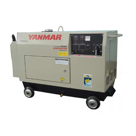
Yanmar mase marine I.S. 3.5 Instruction manual

masemase
masemase
mase
GENERATORS
MANUALE OFFICINA
WORKSHOP MANUAL
I.S. 3.5
I.S. 4.0
50 Hz
60 Hz
I
GB
REV.0 A.A. 15-02-02 cod.42142

IS 3.5 - 4.0
2
IGB
INDICE
Indice
1 Identificazione della macchina .............. 5
1.1 Composizione dei gruppi elettrogeni ........... 5
2 TABELLA ATTREZZI .................................. 9
3 ALTERNATORE ........................................ 13
3.1 Statore ...................................................... 15
3.1.1 Avvolgimenti di potenza............................. 15
3.1.2 Avvolgimenti di eccitazione ....................... 17
3.1.3 Termostato alternatore .............................. 17
3.1.4 Avvolgimenti di carica batteria ................... 19
3.2 Rotore ....................................................... 21
3.2.1 Avvolgimento di rotore (n°2) ...................... 21
3.2.2 Diodi rotore (n°2) ....................................... 23
3.2.3 Varistori rotore (n°2) .................................. 23
3.3 Condensatori ............................................ 25
4 MOTORE .................................................. 27
4.1 Caratteristiche tecniche ............................ 25
4.2 Manutenzione ........................................... 28
4.3 Tavola guasti ............................................. 30
4.4 Combustibile ............................................. 35
4.5 Pompa gasolio elettrica ............................ 37
4.6 Lubrificazione............................................ 39
5 SENSORI ................................................. 41
5.1 Termostato testata motore aperto ............. 41
5.2 Termostato motore a circuito chiuso (mare)43
5.3 Pressostato olio........................................ 45
6 RAFFREDDAMENTO ................................ 47
6.1 Impianto “acqua mare/circuito chiuso" ...... 47
6.2 Pompa acqua ........................................... 49
6.3 Cinghia pompa acqua ............................... 51
6.4 Scambiatore di calore acqua/aria.............. 53
7 REGOLAZIONI ......................................... 55
7.1 Regolazione dei giri .................................. 55
7.2 Regolazione serrature e maniglie .............. 57
7.3 Pulizia filtro aria motore ............................ 59
7.4 Controllo livello olio ................................... 61
7.5 Pulizia filtro olio motore ............................ 61
8 IMPIANTO ELETTRICO ........................... 63
8.1 Circuito di comando .................................. 63
8.1.1 Cavo multipolare ....................................... 69
8.2 Elettrovalvola ............................................. 71
8.3 Interruttore termico (AC circuit breaker) .... 73
8.4 Cablaggio motore ...................................... 75
8.5 Caricabatteria ........................................... 77
8.6 Fusibile ..................................................... 79
8.7 Motorino avviamento ................................. 81
8.8 Batteria ..................................................... 83
9 SMONTAGGIO ......................................... 85
9.1 Rimozione della cassa .............................. 85
9.2 Rimozione alternatore ............................... 95
9.3 Rimozione del coperchio alternatore lato ......
cuscinetto ................................................. 97
9.4 Rimozione dello statore ............................ 99
9.5 Rimozione del rotore ............................... 101
9.6 Rimozione del cuscinetto di rotore .......... 101
Index
1 Machine identification........................5
1.1 Generatorscomposition .......................... 5
2 TOOLTABLE .......................................... 9
3 ALTERNATOR ..................................... 13
3.1 Stator.................................................... 15
3.1.1 Powerwindings..................................... 15
3.1.2 Excitation windings ............................... 17
3.1.3 Alternator thermostat ............................ 17
3.1.4 Battery charger windings ................ 19
3.2 Rotor ..................................................... 21
3.2.1 Rotorwinding(n°2) ............................... 21
3.2.2 Rotor diodes (n°2) ................................. 23
3.2.3 Rotor varistors (n°2) ............................ 23
3.3 Capacitors ............................................ 25
4 ENGINE ................................................ 27
4.1 Technical features ................................. 25
4.2 Maintenance ......................................... 28
4.3 Trouble-shooting ................................... 30
4.4 Fuel ...................................................... 35
4.5 Electric diesel fuel pump ...................... 37
4.6 Lubrication ............................................ 39
5 SENSORS ............................................ 41
5.1 Closed-circuit engine thermal switch .... 41
5.2 Open-circuit engine thermostat (sea) .... 43
5.3 Oil pressure switch ............................... 45
6 SEA WATER COOLING ....................... 47
6.1 Seawater/closed-circuit system ............ 47
6.2 Water pump .......................................... 49
6.3 Water pump belt ................................... 51
6.4 Water/air heat exchanger ...................... 53
7 ADJUSTMENTS ................................... 55
7.1 Rpm adjustment ................................... 55
7.2 Lock and handle adjustment ................. 57
7.3 Engine air filter cleaning .................. 59
7.4 Level oil check ...................................... 61
7.5 Engine oil filter cleaning ........................ 61
8 ELECTRICAL SYSTEM ........................ 63
8.1 Command circuit .................................. 63
8.1.1 Multicore cable ..................................... 69
8.2 Stop solenoid........................................ 71
8.3 Thermal switch (ACcircuit breaker) ........... 73
8.4 Enginewiring ........................................ 75
8.5 Battery charger ..................................... 77
8.6 Fuse ..................................................... 79
8.7 Starter motor ........................................ 81
8.8 Battery .................................................. 83
9 DISASSEMBLY .................................... 85
9.1 Removing the casing............................. 85
9.2 Removing the alternator ........................ 95
9.3 Removing the alternator cover
on the bearing side ............................... 97
9.4 Removing the stator .............................. 99
9.5 Removingthe rotor ...............................101
9.6 Removing the rotor bearing ..................101
IS 3.5 - 4.0
3
IGB
INDEX
COPPIE DI SERRAGGIO VITI ............... 101
RICAMBI ................................................ 102
MOTORE ................................................ 103
ALTERNATORE ...................................... 105
CASSA ................................................... 107
MARENIZZAZIONE ................................. 109
PANNELLO COMANDI ............................ 111
SCHEMA ELETTRICO ............................. 112
SCREW SHUT .....................................101
SPARE PARTS ....................................102
ENGINE ...............................................103
ALTERNATOR .....................................105
FRAME ................................................107
SEA WATER .......................................109
CONTROLPANEL ...............................111
WIRING DIAGRAM ................................. 112

IS 3.5 - 4.0
4
1
3
2
4
1 IDENTIFICAZIONE MACCHINA
1
10
SERIAL No.
1
2
3
5
6
7
8
9
4
5
6
7

IS 3.5 - 4.0
5
1 Machine identification
(Fig.1)
1 - Manufacturer
2 - Machine code
3 - Year of construction
4 - Power factor
5 - Declared frequency
6 - Continuous power
7 - Rated voltage
8 - Rated current
9 - Weight
10 - Serial number
The machine code number, the serial number
and the year of construction must always be
quoted when contacting the manufacturer for
information, requests for spare parts, etc.
1 Identificazione della macchina
(Fig.1)
1 - Costruttore
2 - Codice macchina
3 - Anno di costruzione
4 - Fattore di potenza
5 - Frequenza dichiarata
6 - Potenza continua
7 - Tensione nominale
8 - Corrente nominale
9 - Peso
10 - Numero di serie
I dati che identificano il nro di codice della macchi-
na, il nro di serie e l’anno di costruzione devono
essere sempre precisati al Costruttore per infor-
mazioni, richieste di ricambi, ecc.
1 MACHINE IDENTIFICATION
1.1 Composizione dei gruppi elettrogeni
I gruppi elettrogeni sono composti essenzial-
mente dai seguenti componenti (Fig.1-2):
1 - Cassa insonorizzante
2 - Portello di accesso superiore
3 - Portello di accesso laterale
4 - Staffe di ancoraggio
5 - Raccordoscaricofumieacquadiraffreddamento
6 - Raccordo collegamento presa acqua mare
7 - Raccordi di collegamento a serbatoio carburante
1.1 Generators composition
The generators are essentially composed of
the following components (Fig.1-2):
1- Soundproof casing
2- Top access door
3- Side access door
4- Anchoring brackets
5- Exhaust and cooling water pipe fitting
6- Seawater intake connection pipe fitting
7- Connection pipe fittings to fuel tank

IS 3.5 - 4.0
6
10
20
17
1 IDENTIFICAZIONE MACCHINA
14
19
13
9
12
16
18
15
2
11
21
22
8A
8B
23

IS 3.5 - 4.0
7
8A-Connection to battery +
8B-Connection to battery -
9- RPM adjusting screw of engine
10- Engine air filter
11- Engine oil extraction pump
12- Seawater pump
13- Fuel pump
14- Oil filter cartridge
15- Oil fillercap
16- Electric line connection box
17- Battery charger regolator
18- Water/air heat exchanger
19- Exhaust manifold
20- Starter motor
21- Remote control panel connector
22- Capacitor
23- Fuse
8A- Collegamento batteria +
8B- Collegamento batteria -
9 - Vite di regolazione giri del motore
10- Filtro aria motore
11- Pompa estrazione olio motore
12- Pompa acqua mare
13- Pompa carburante
14- Cartuccia filtro olio
15- Tappo carico olio
16- Scatola collegamento linea elettrica
17- Regolatorecaricabatteria
18- Scambiatore di calore acqua/aria
19- Collettore scarico
20- Motorinodiavviamento
21 - Connettore pannello di comando a distanza
22- Condensatore
23- Fusibile
1 MACHINE IDENTIFICATION

IS 3.5 - 4.0
8
2 TABELLA ATTREZZI
3

IS 3.5 - 4.0
9
2 TOOL TABLE
2 TOOL TABLE
Denomination: Torque spanner
Use: To tighten the nuts and bolts to the
prescribed torque
Denomination: Battery tester
Use: To check the electrolyte level of the battery
Denomination: Digital thermometer
Use: Measures the temperature of the
components
Denomination: Contact tachometer
Use: Measures the rpm of the rotary shaft by
bringing the indicator tip in contact with the
central hole of the shaft.
Denomination: Photocell tachometer
Use: Allows measuring the rpm of the rotary
shaft when it is in uncomfortable positions,
holding the tachometer at a certain distance.
Denomination: Terminal tachometer for high-
pressure fuel pipe
Use: Measures the engine rpm using a pulse
system not taking into account the centre of the
rotary shaft and the circumference of the rotating
object.
2 Tabella attrezzi
Denominazione : Chiave torsiometrica
Uso : Serve per serrare bulloni e dadi alla
coppia prescritta
Denominazione : Tester batteria
Uso : Controlla lo stato di carica dell’elettrolito
della batteria
Denominazione : Termometro digitale
Uso : Misura la temperatura dei componenti
Denominazione : Tachimetro a contatto
Uso : Misura i giri/min. dell’albero rotante
portando la testa dell’indicatore a contatto del
foro centrale dell’albero.
Denominazione : Tachimetro a fotocellula
Uso : Permette di rilevare i giri dell’albero rotante
quando questo si trova in posizione scomode,
tenendo il tachimetro ad una certa distanza.
Denominazione : Tachimetro a morsetto per
tubo combustibile ad alta pressione
Uso : Misura i giri/min. del motore usando un
sistema ad impulsi, senza tener conto del centro
dell’albero rotante e della circonferenza
dell’oggetto rotante

IS 3.5 - 4.0
10
2 TABELLA ATTREZZI
4

IS 3.5 - 4.0
11
Denominazione : Tester
Uso : Misura la tensione AC/DC , le resistenze
ed i diodi
Denominazione : Pinza amperometrica
Uso : Misura la tensione AC, frequenza (n° di
giri motore) e corrente AC.
Si può quindi risalire alla potenza che stiamo
prelevando dal generatore.
Denominazione : Amperometro
Uso : Misura la corrente di linea collegandolo in
serie
Denominazione : Frequenzimetro
Uso : Misura la frequenza (n° di giri motore)
collegandolo in parallelo alla linea 230-115V del
generatore
Denominazione : Estrattore
Uso : Utilizzato per l'estrazione del coperchio
cuscinetto alternatore, e del cuscinetto di rotore
2 TOOL TABLE
Denomination: Tester
Use: Measures the AC/DC voltage, the resistors
and the diodes
Denomination: Amperometric caliper
Use: Measures the AC voltage, frequency
(engine rpm) and AC current.
The power drawn from the generator can thus
be measured.
Denomination:Ammeter
Use: Measures the line current connecting it in
series
Denomination:Frequency meter
Use: Measures the frequency (engine rpm)
connecting it in parallel to the 230-115V line of
the generator.
Denomination: Extractor
Use: Used to extract the alternator bearing
cover and the rotor bearing.

IS 3.5 - 4.0
12
3 ALTERNATORE
5
ALTERNATORE 50 Hz 60 Hz
Tipo
Raffreddamento
Tensione (V) 115 - 230 120 - 240
Frequenza (Hz) 50 60
Amps 26 - 13 26,6 - 13,3
Potenza max. (Kw) 3 3,2
Potenza cont. (Kw) 2,7 2,9
Uscita Carica batterie (A-V)
Fattore di potenza ( cos ø )
Classe d'isolamento
Stabilità di tensione
Stabilità di frequenza
Sincrono, 2-poli, autoeccitato
±10%
±5%
Aria / acqua ( Intercooler W/A )
10-12
1
H
ALTERNATOR 50 Hz 60Hz
Type
Cooling
Voltage (V) 115 - 230 120 - 240
Frequency (Hz) 50 60
Amps 26 - 13 26.6 - 13.3
Max. power (Kw) 3 3.2
Continuous power (Kw) 2.7 2.9
Battery charging output (A-V)
Power factor ( cos ø )
Insulating class
Voltage stability
Frequency stability
10 - 12
Air/water ( Intercooler W/A )
1
H
±5%
±10%
Brush less synchronous, 2-poles
self-excited

IS 3.5 - 4.0
13
3 ALTERNATOR
3 ALTERNATOR
The generators of the IS 3.5/4.0, series are
equipped with a brushless, synchronous, 2-pole,
self-regulating, self-excited alternator with 1
capacitor (Fig. 2 Ref. 22) connected to the auxiliary
winding for stator excitation. The alternator
generates alternate voltage available at the
terminalsat a frequencyof 50/60Hz (corresponding
to the speed of the prime mover of 3000/3600 rpm)
according to the principle described below.
Upon starting, the rotor magnetism (residual
magnetism of the nucleus) induces a voltage in the
auxiliary excitation windings.
This voltage is applied to the capacitor, and makes
a capacitive current circulate in the closed circuit
composedofthe capacitor andtheauxiliary winding.
This current produces a magnetic field which
strengthens the rotor magnetism generating a
voltage inside it which, rectified by the diodes,
makes a continuous current circulate in the rotor
field windings.
The rotating magnetic field due to circulation of this
current in its turn generates in the primary winding
the rated voltage to the generator terminals.
TESTS
All the resistance measurements are made with
the alternator cold, ambient temperature 10 - 30
°C, and with instrumentation such as to allow
reading the values indicated.
The tolerance with respect to the values listed is
approximately ± 10%.
Approximate readings made with instruments with
inadequate range, can only indicate continuity of
the winding but do not give an indication of any
short-circuits.
N.B.
Apart from the failure possibilities indicated below,
there might be one or more earth windings. It is
therefore recommended to test these possibilities,
checking with a tester that there is no continuity
between the various windings (identified in the
following paragraphs) to earth and between them.
3 ALTERNATORE
I generatori della serie IS 3.5/4.0, sono dotati di
alternatore senza spazzole, sincrono, a 2 poli,
autoregolato, autoeccitato, con 1 condensatore
(fig. 2 rif. 22) collegato all'avvolgimento ausiliario
di eccitazione statore. L’alternatore genera una
tensione alternata, disponibile ai morsetti a una
frequenza di 50/60 Hz. (Corrispondenti alla veloci-
tà del motore primo di 3000/3600 rpm) secondo il
principio di seguito descritto.
All’avviamentoilmagnetismodi rotore (magnetismo
residuo del nucleo) induce negli avvolgimenti
ausiliari di eccitazione una tensione.
Questa tensione è applicata al condensatore, e fa
circolare nel circuito chiuso, costituito dal
condensatore e dall’avvolgimento ausiliario, una
corrente capacitiva.
Questa corrente produce un campo magnetico
che rafforza il magnetismo di rotore, generando in
esso una tensione che, raddrizzata dai diodi, fa
circolare una corrente continua negli avvolgimenti
induttori di rotore.
Ilcampo magnetico rotantedovuto allacircolazione
di questa corrente genera a sua volta
nell’avvolgimento principale la tensione nominale
ai morsetti del generatore.
CONTROLLI
Tutte le misure di resistenza si intendono eseguite
ad alternatore freddo, temperatura ambiente 10 -
30 °C e con strumentazione tale da permettere la
lettura dei valori indicati.
La tolleranza rispetto ai valori riportati è
indicativamente ± 10%.
Letture approssimative, eseguite con strumenti di
portata non adeguata, possono unicamente
indicare la continuità dell’avvolgimento ma non
danno indicazioni su eventuali corto circuiti.
N.B.
Oltre alle possibilità di guasto che sono indicate
in seguito si può presentare il caso di uno o più
avvolgimenti a massa. Si consiglia quindi di
controllare queste eventualità verificando con
un tester che non ci sia continuità fra i vari
avvolgimenti (identificati nei paragrafi
successivi) verso massa e fra gli stessi.

IS 3.5 - 4.0
14
3 ALTERNATORE
6
144
33
20 10
20
50(60)
5
2
311
4
1
2
3
4

IS 3.5 - 4.0
15
3.1 Statore (Fig.6, rif5)
3.1.1 Avvolgimenti di potenza (Fig.6, rif.1)
Caratteristiche:
Metodo di controllo:
- Assicurarsi che il termico di bordo sia armato.
- Scollegare dalla morsettiera i cavi di potenza
contrassegnati dalle lettere P1F1P2 F2
-Verificare che la resistenza fra le estremità di
entrambe le coppie di cavi P1F1 e P2F2 rientri
nei valori indicati in tabella.
N.B. La resistenza totale dell'avvolgimento (nel
collegamento 220 V o 240 V) si misura
ponticellando F1e P2. La misura effettuata fra i
punti P1e F2sarà il doppio del valore indicato in
tabella.
RIMEDIO: Sostituire lo statore
A
TTENZIONE: Gli avvolgimenti sono trattati
con resine e vernici per ambienti con clima
umido-salino. Se tali trattamenti sono
deteriorati, sostituire !
3 ALTERNATOR
3.1 Stator (Fig.6, ref5)
3.1.1 Power windings (Fig.6, ref.1)
Features:
Test method:
- Ensure that the onboard thermal switch is ar-
moured
- Disconnect from the terminal board, the wires
coming from the stator, marked by the letters P1F1
P2F2.
- Verify that the resistance values between the two
pairs of wire terminals P1F1and P2F2 are within the
limits as reported in the table above.
N.B. The total resistance value for power winding
(220 V 240 V) is measured connecting F1and P2.
the resistance value measured between P1and F2
is double of that indicated in the table above.
REMEDY: Replace the stator
WARNING: The windings have been treated
with resin and paint for humid-saline climates. If
these treatments have deteriorated, replace !
IS 3,5 IS 4,0
P1 Rosso-Red P1 Rosso-Red
F1 Giallo-Yellow F1 Bianco-White
P2 Verde-Green P2 Nero-black
F2 Blù-Blue F2 Blù-Blue
50Hz 60Hz
n° colore n° colore
POTENZA
0,603 0,514
0,603 0,514
POTENZA /
POWER
n° Colore/n° Color n° Colore/n° Color

IS 3.5 - 4.0
16
3 ALTERNATORE
7
2
8
1

IS 3.5 - 4.0
17
IGB
3.1.2 Avvolgimenti di eccitazione (Fig.6, rif.2)
Caratteristiche:
Metodo di controllo
- Togliere il cappuccio di protezione.
- Scollegare il condensatore (Fig. 7 rif.1) dai
cavi provenienti dallo statore (Fig. 7 rif.2).
- Verificare che la resistenza fra le estremità dei
cavi rientri nei valori indicati in tabella.
RIMEDIO: Sostituire lo statore.
3.1.3 Termostato Alternatore (Fig.6, rif.4)
Caratteristiche: Normalmente chiuso.
Temperatura d’intervento 180° C.
Metodo di controllo:
-Accedere alla zona morsettiera allacciamento
potenza (Fig. 8).
-Scollegare i fili rossi (o bianchi) da 1.0mm2da
morsetti 17 e 18.
-Verificare la continuità fra le due estremità dei
cavi.
RIMEDIO: Sostituire lo statore
N.B.: Il termostato alternatore, può intervenire per
sovraccarico o per sovratemperatura.
Verificare quindi, se è necessario, i carichi applicati
e la temperatura d’esercizio del generatore, con
particolare attenzione alla sua installazione.
3 ALTERNATOR
3.1.2 Excitation windings (Fig.6, ref.2)
Features:
Test method
- Remove the protective cap.
- Disconnect the cables (Fig. 7 Ref.1) coming
from the stator from the capacitor (Fig. 7 Ref.2).
- Check that the resistance between the ends of
the cables falls within the values indicated in the
table.
REMEDY: Replace the stator.
3.1.3 Alternator thermostat (Fig.6, ref.4)
Characteristics: Normally closed.
Operating temperature: 180° C.
Test method:
-Access the power connection terminal board
area (Fig. 8).
-Disconnect the 1.0 mm2red (or white) wires
from the 17 and 18 terminal board.
-Check continuity between the two ends of the
cables.
REMEDY: Replace the stator
N.B.: The alternator thermostat may intervene
because of an overload or overtemperature.
Therefore, check if necessary, the applied loads
and the operating temperature of the generator
with particular attention to its installation.
n° colore IS 3,5 n° colore IS 4,0
0Rosso-Red 0Rosso-Red
50 Nero-black 60 Bianco-White
ECCITAZIONE 2,76 2,29
50Hz 60Hz
Colore / Color
ECCITAZIONE /
EXCITATION
Colore / Color

IS 3.5 - 4.0
18
9
1
2

IS 3.5 - 4.0
19
3.1.4 Avvolgimenti di carica batteria
(Fig.6, rif.3)
Caratteristiche:
Metodo di controllo
- Scollegare la batteria dal gruppo.
- Scollegate i 2 cavi dal regolatore
contrassegnati 5 o 6 (Fig. 9 rif.1) (sul
regolatore, corrispondono i simboli "~" "~") e
verificare che la resistenza rientri nei valori
indicati in tabella.
- Verificare che la resistenza fra ciascun cavo
ed il filo nero (sez.2.5mm2 contrassegnato +
Fig. 9 rif.2), sia la metà del valore indicato in
tabella
IS 3,5 IS 4,0
5Blù-Blue 6Verde-Green
CARICA
BATTERIA 0,13 0,11
n° colore n° colore
50Hz 60Hz
3.1.4 Battery charger windings
(Fig.6, Ref.3)
Characteristics:
Test method
- Disconnect the battery from the generator.
- Disconnect the 2 cables marked 5 or 6 (Fig. 9
Ref.1) from the regulator (the corresponding
symbols “~” “~” on the regulator) and check that
the resistance falls within the values indicated in
the table.
- Check that the resistance between each cable
and the black wire (2.5 mm2cross-section
marked + Fig. 9 Ref.2 ) is half the value
indicated in the table.

IS 3.5 - 4.0
20
1
3 ALTERNATORE
10
This manual suits for next models
1
Table of contents
Other Yanmar Portable Generator manuals

Yanmar
Yanmar YDG Series User manual

Yanmar
Yanmar LIGHT BOY LB446HB User manual

Yanmar
Yanmar mase Marine I.S. 5.0 Instruction manual

Yanmar
Yanmar neoTower User manual

Yanmar
Yanmar YDG5001SE User manual

Yanmar
Yanmar Mase I.S. 6.5 User manual

Yanmar
Yanmar TNE Series User manual

Yanmar
Yanmar YDG Series User manual
Popular Portable Generator manuals by other brands

LIPOWER
LIPOWER G1600L user manual

Coleman
Coleman Powermate PM0525300 user manual

Hyundai power products
Hyundai power products HY6500SEi user manual

Keysight Technologies
Keysight Technologies E8267D Installation notes

Briggs & Stratton
Briggs & Stratton 30385 Illustrated parts list

Sterling Power Products
Sterling Power Products PMP1 instructions