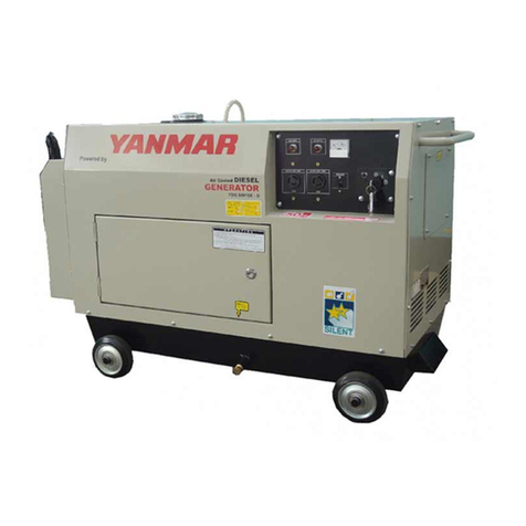
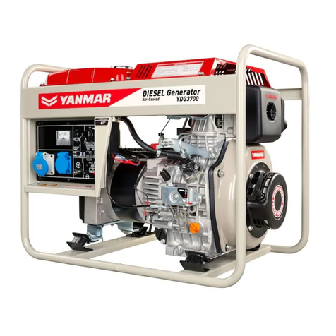
Yanmar LIGHT BOY LB446HB User manual


FOREWORD
This manual explains the service procedure for Yanmar floodlight projector model
LB446HB & LB446H.
Please use this manual for correct, quick, safe servicing of the floodlight projector.
Please be advised that the contents of this manual may be different from actual
floodlight projector because of any later modification of parts or specifications for
improving the quality.

1.Safety.................................................................................................................... 1-2
1-1. Warning Symbols.......................................................................................... 1-2
1-2-1. Service Shop (Location).................................................................... 1-3
1-2-2. Working Wear ................................................................................... 1-3
1-2. Loading generator.......................................................................................... 1-3
1-2-3. Tools to Be Used............................................................................... 1-4
1-2-4. Parts.................................................................................................. 1-4
1-2-5. Bolt Tightening Torque...................................................................... 1-4
1-2-6. Product Handling............................................................................... 1-4
1-2-7. Installation ......................................................................................... 1-5
1-2-8. Transport ........................................................................................... 1-5
1-2-9. Warning Labels ................................................................................. 1-6
2.Outline of Floodlight Projector .......................................................................... 2-2
2-1. Specifications................................................................................................ 2-2
2-2. External View and Components of Floodlight Projector ................................ 2-3
3.Structure of Floodlight Projector....................................................................... 3-2
3-1. Outline of Structure....................................................................................... 3-2
3-2. Electrical Group ........................................................................................... 3-2
3-2-1. Balloon Unit....................................................................................... 3-3
1) Balloon assembly ........................................................................ 3-3
2) Stand assembly............................................................................ 3-4
3-2-2. Lamp Stand Unit ............................................................................... 3-5
1) Lighting unit assembly.................................................................. 3-5
2) Lamp stand assembly .................................................................. 3-5
3-2-3. Power Cable Unit .............................................................................. 3-6
3-3. Mast Group .................................................................................................... 3-7
3-4. Outrigger group.............................................................................................. 3-8
3-5-1. Base Plate Unit ................................................................................. 3-9
3-5. Base Plate Group .......................................................................................... 3-9
3-5-2. Steering Unit ................................................................................... 3-10
3-5-3. Brake Unit ....................................................................................... 3-10
4.Disassembly and Assembly ............................................................................... 4-2
4-1. Before Starting Operation ............................................................................ 4-2
4-1-1. Grasp of Service History ................................................................... 4-2
4-1-2. Preparing the Necessary Tools, Parts and Materials........................ 4-2
CONTENTS
4-2. Disassembly and Assembly Procedures ..................................................... 4-2
4-2-1. General Instructions .......................................................................... 4-2
1) Disassembly ................................................................................. 4-2
2) Reassembly.................................................................................. 4-2
4-2-2. Disassembly Procedure of Each Assembly /Unit /Group .................. 4-3
4-2-3. Disconnection of Couplers ................................................................ 4-4
1) Removal of connector covers....................................................... 4-4
2) Disconnection of coupler .............................................................. 4-5
4-2-4. Removal of Balloon Assembly .......................................................... 4-6
4-2-5. Removal of Lighting Unit Assembly .................................................. 4-7
4-2-6. Removal of Pin (Socket) Contact ...................................................... 4-8
4-2-7. Removal of Stand Assembly ............................................................. 4-9
4-2-8. Removal of Lamp Stand Assembly ................................................... 4-9
4-2-9. Unloading of Generator................................................................... 4-10
4-2-10. Removal of Mast Group ................................................................ 4-11
4-2-11. Removal of Outrigger Group ......................................................... 4-11
4-2-12. Disassembly of Balloon Assembly ................................................ 4-12
4-2-13. Disassembly of Stand Assembly................................................... 4-14
4-2-14. Disassembly of Lighting Unit Assembly ........................................ 4-14
4-2-15. Disassembly of Lamp Stand Assembly......................................... 4-15
4-2-16. Disassembly of Power Cable Unit................................................. 4-15
4-2-17. Disassembly of Mast Group .......................................................... 4-16
4-2-18. Disassembly of Outrigger Group................................................... 4-17
4-2-19. Disassembly of Base Plate Unit .................................................... 4-18
4-2-20. Disassembly of Steering Unit ........................................................ 4-19
4-2-21. Disassembly of Brake Unit ............................................................ 4-20
5.Inspection and Maintenance .............................................................................. 5-2
5-1. Electrical Group ............................................................................................. 5-2
5-1-1. Balloon Unit....................................................................................... 5-2
1) Balloon assembly ......................................................................... 5-2
5-1-2. Lamp Stand Unit ............................................................................... 5-4
1) Lighting unit assembly.................................................................. 5-4
2) Lamp stand assembly .................................................................. 5-5
5-1-3. Replacement of Balloon Unit and Lamp Stand Unit .......................... 5-6
1) Replacement ................................................................................ 5-6
2) Storage of removed balloon unit and lamp stand unit .................. 5-6

5-1-4. Power Cable Unit .............................................................................. 5-6
1) Connection of power cable.......................................................... 5-6
2) Voltage check............................................................................... 5-7
3) Replacement of lamp cable.......................................................... 5-8
5-2-1. Mast Group ....................................................................................... 5-9
1) Shaft of mast ................................................................................ 5-9
2) Sliding surface of mast ................................................................. 5-9
3) Winch ........................................................................................... 5-9
5-2. Mast Group .................................................................................................... 5-9
4) Wire ............................................................................................ 5-10
5-4. Base Plate Group ........................................................................................ 5-12
5-4-1. Base Plate Unit ............................................................................... 5-12
5-4-2. Steering Unit ................................................................................... 5-12
5-3. Outrigger Group........................................................................................... 5-12
5-4-3. Brake Unit ....................................................................................... 5-13
5-5. Grounding .................................................................................................... 5-13
6.Periodic Inspection Items................................................................................... 6-2
6-1. Inspection Items and Intervals ....................................................................... 6-2
7.Circuit ................................................................................................................... 7-2
7-1. Electrical Circuit ............................................................................................. 7-2
7-1-1. How to Read Electrical Circuit Diagram ............................................ 7-2
7-1-2. Electrical Circuit Diagram.................................................................. 7-2
8.Tools, Instruments and Other Materials for
Inspection and Maintenance ................................................................................. 8-2
8-1. Machines, Tools and Instruments.................................................................. 8-2
8-1-1. General Tools.................................................................................... 8-2
8-1-2. Special Tool ...................................................................................... 8-3
8-1-3. Measuring Instrument ....................................................................... 8-3
8-1-4. Materials Required ............................................................................ 8-3
9.Bolts and Nuts Tightening Torques .................................................................. 9-2
9-1. General Instructions....................................................................................... 9-2
9-2. Major Bolts and Nuts ..................................................................................... 9-3
10.Troubleshooting .............................................................................................. 10-2
10-1. Troubleshooting Procedures...................................................................... 10-2

1-1
Safety

1-2
1. Warning Symbols
1. Safety
zMost accidents are caused by negligence of basic safety rules and precautions.
Avoiding possible cause is important for accident prevention. Be sure to read this manual carefully
for full understanding of safety precautions and appropriate service/inspection procedures before
starting actual repair or service jobs. Repair or service jobs without sufficient knowledge may lead to
unexpected accidents.
zIt is not possible to cover all possible accidents in repair or service in the manual.
It is, therefore, necessary to pay sufficient attention to safety in various jobs not indicated with the
following warning symbols. Especially for the safety in conducting various jobs not covered herein,
receive instructions from a knowledgeable leader.
zThe warning symbols used in this manual and their meanings are as follows:
DANGER- Indicates an imminently hazardous job which, if not
conducted correctly, will result in death or serious injury.
CAUTION- Indicates a potentially hazardous job which, if not
conducted correctly, may result in minor or moderate injury.
zThe notice sign used in this manual and its meaning are as follows:
NOTICE- Indicates an important point in service operation
which, if not observed, the product performance and quality
may not be guaranteed.
1-1. Warning Symbols
[NOTICE]

1. Loading generator, Service Shop (Location)
1-3
zAlways observe the following instructions for safe repair and maintenance jobs:
1-2-1. Service Shop (Location)
Well-ventilated location
zSelect a well-ventilated location for conducting floodlight projector operation,
parts welding or polishing the paint with sandpaper.
[Non-observance]
Very dangerous for human health since inhalation of poisonous gas or dust
is possible.
Sufficiently wide, flat location
zThe floor of the service shop (area) for inspection and service shall be suffi-
ciently wide and flat without any hole.
[Non-observance]
Dangerous since unexpected accidents such as a violent fall may occur.
Cleaned location arranged in good order
zThe floor surface shall be free from dust, dirt or oil without any flammable
substance or parts on it.
[Non-observance]
Unexpected accidents may arise.
Brightly and safely illuminated location
zThe working area shall be illuminated in a safe manner with sufficient bright-
ness. When operating in a dark place involving poor visibility, use a safe,
portable flashlight. The bulb shall be covered with wire cage.
[Non-observance]
Accidental breaking of the bulb may cause ignition of leaking oil.
Location with fire-extinguishing equipment
zAlways work in the neighborhood of a first aid kit and fire extinguisher in
preparation for an accidental fire.
1-2-2. Working Wear
Wear for safe operation
zWear protective items such as a cap, safety shoes and working wear match-
ing the job to be done. Especially select a working wear fitting your body.
[Non-observance]
Critical accidents such as trapping in a machine may arise.
1-2. Loading generator

1. Loading generator, Tools to Be Used
1-4
1-2-3. Tools to Be Used
Proper supporting and lifting
zNever operate when the product is supported with blocks or wooden pieces
or only with a jack. Always use a crane with sufficient allowance in limit load
or with rigid jack(s) for lifting and supporting the product.
[Non-observance]
Severe accidents may arise.
Use of appropriate tools
zUse appropriate tools for individual jobs. Use a correct-size tool when loos-
ening or tightening a nut or bolt.
[Non-observance]
A severe injury or damage to a machine or part may arise.
1-2-4. Parts
Always use genuine items
[Non-observance]
Shortening of the machine life or unexpected accidents may arise.
1-2-5. Bolt Tightening Torque
Always tighten to torque specified in the manual, if any
[Non-observance]
Loosening or falling will arise to damage the machine or parts or cause inju-
ries.
1-2-6. Product Handling
Pay attention to hot parts
zThe lamps, balloon and the lighting units are hot while lamps are on and right
after they are turned off. Take great care in handling them.
[Non-observance]
Scald may occur.
Keep clear of pinch-point
zKeep clear of pinch-point of the mast and the lamp stand when handling
them.
[Non-observance]
An injury may be caused by unexpected entrapping.
[NOTICE]
This manual suits for next models
1
Other Yanmar Portable Generator manuals

Yanmar
Yanmar mase marine I.S. 3.5 Instruction manual

Yanmar
Yanmar Mase I.S. 6.5 User manual

Yanmar
Yanmar YDG Series User manual

Yanmar
Yanmar YDG Series User manual

Yanmar
Yanmar neoTower User manual

Yanmar
Yanmar TNE Series User manual

Yanmar
Yanmar mase Marine I.S. 5.0 Instruction manual

Yanmar
Yanmar YDG5001SE User manual