Yanmar TNE Series User manual

Installation Guide For PowerHouse Generators
DRAFT
Not For Release
Supplied By M+H Power System
This manual is for guidance only and does replace any federal or local laws. Please
contact a licensed installer for more details relevant to your installation in regards to this.
Version 0.2

Contents
1. Manuals
2. Wiring Diagram for Controller
3. Visual Inspection
4. Unpacking Crate
5. Exhaust
6. Positioning of Generator
7. Expansion bottle install
8. Fuel System
9. Pre Starting Checks
10. Cranking Battery
11. Controller
12. Starting Generator
13. Servicing Requirements & Parts
14. Generator Do’s and Don’ts
15. Warranty Statement
2

Manuals
Please read and understand and all the manuals and supporting
documentation in regards to this generator. Some of these are shown below:
3

Wiring Diagram for Controller
FUSE
12VDC
BATTERY
BOSCH, MARELLI, LUCAS
ALTERNATOR TYPE
K3
C/B
30A
GLOW PLUGS
CRANK MOTOR
-
K3
K1
+
STOP
EMERGENCY
F4
50
+B W
+D
K1
K2
15/54
30
REMOTE START
ENGINE TEMPERATURE
OIL PRESSURE
(OPTIONAL)
FUEL LEVEL
KEYSWITCH
OFF
RUN
START
911
START RELAY
FUEL SOLENOID VALVE
"W" SPEED INPUT
G
1053
4
8
7
6
21
PDM1
NO VOLTS
REMOTE START 12V
REMOTE
START
4

Visual Inspection
Before going to site please ensure unit is complete and free from shipping
damage. Unit should come as pictured below:
Please ensure all accessories are included as shown in picture below
(including hoses):
Once this is done unit can then be shipped direct to site for installation. Once
there please complete this inspection again before commencing work.
5

Unpacking the Crate
Please take care when unpacking generator as not to damage unit and
controller. Please note: use suitable size tools and equipment to ensure the
unit is not damaged. On completion the unit should look like this or similar.
When removing generator from base please use correct lifting eye or correct
lifting pockets to ensure unit is removed safely. Also please give unit a quick
visual inspection to ensure no obvious sign of damage to unit.
6

Exhaust System
Please remove the U bolts nuts from end of exhaust located at the radiator
end.
Remove the metal insert from the end of the flexible exhaust and slide in the
exhaust pipe end to ensure the 45 degree angle is facing down to stop water
penetration into the system. Tighten up U bolts ensuring the flexible exhaust
is not crushed and tightly holding on to the inserted exhaust pipe.
7

Positioning Of the Generator
When considering where to position generator please ensure genset is
located away from flammable materials.
Have easy access all round to enable work to be carried out easily in the
future (for maintenance).
Also note that the wall of the building needs a hole cut in it to ensure venting
of the radiator. This hole needs to be slightly larger than the radiator and the
cowling mounted on the inside wall. The genset can then be fitted into the
cowling to ensure hot air is released out of the building. Please also ensure
vermin trap (wire mesh is fitted to outside of building).
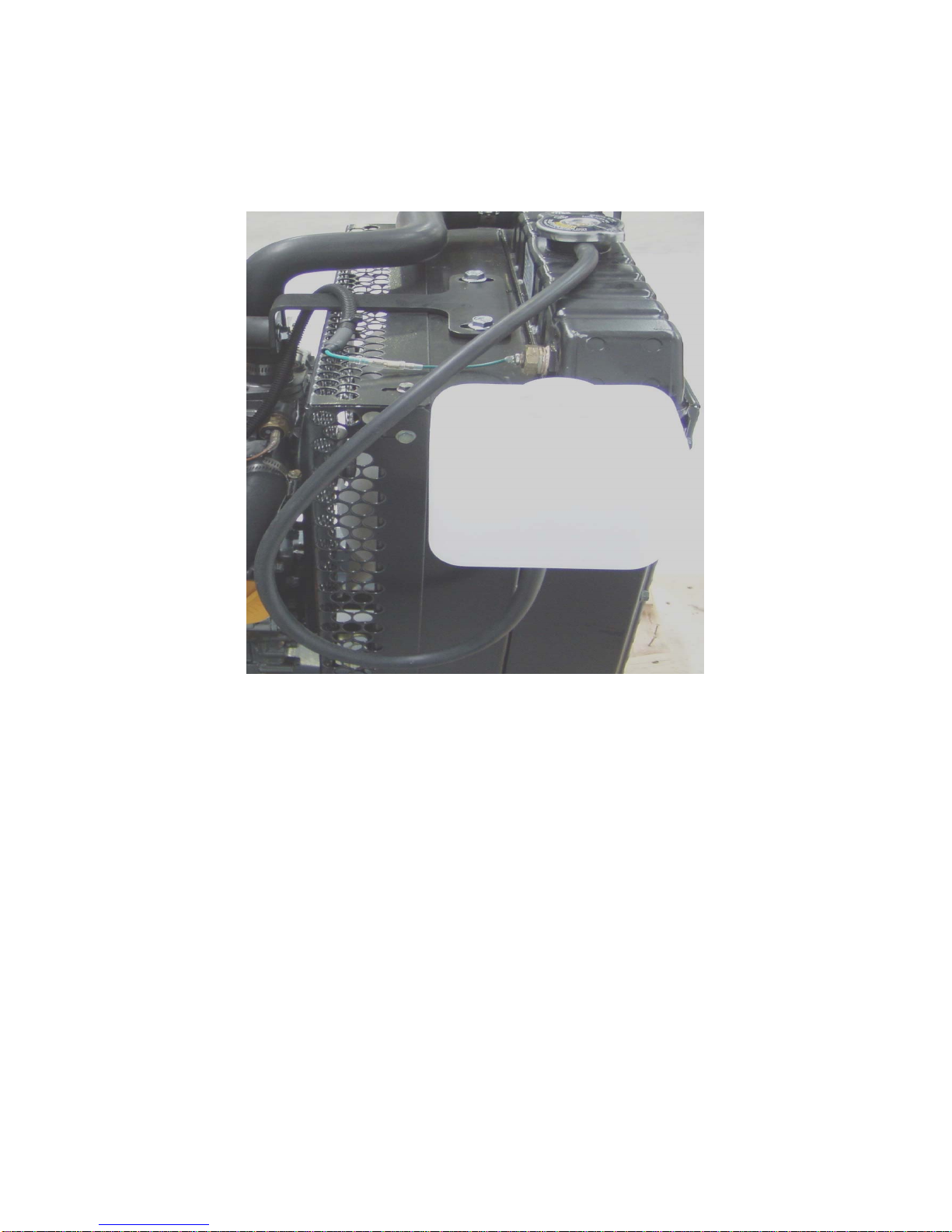
Also note the exhaust has been mounted along the top of the radiator to vent
all the hot exhaust gases out of the room. Please drill a hole capable of
putting the exhaust through. Ensure exhaust is facing down to stop water
from getting into the engine i.e. 45 degree angle is facing down.
Please ensure all holes in the wall are sealed around the edges and the
sealing material is heat retardant, especially around the exhaust system hole.
Once final position of the unit has been decided place the vibration pads
underneath the skid as shown below:
Also ensure adequate ventilation around the unit to ensure air flow. In an
ideal situation this would be cross ventilation to enable engine to breathe.
The generator room needs to be kept clean and tidy, be free from heavy dirt
and dust to ensure a long life span of the electronic components fitted to the
unit.
8

Setting up Water Expansion Bottle
Radiator bottle and hose
Fit hose to radiator as below just below cap.
9

Attach cable tie to hold the hose in position. Ensure hose is not crushed but
held tightly in place.
Fit water bottle to side of radiator and attach hose to bottom of bottle and
fill to the max indicated level with recommended coolant.
Coolant levels also needs to be tested, this can be done at the radiator cap.
Ensure coolant can be touched by your finger; only do once the engine is
cold.
10

Fuel System
Remove bungs from fuel system located in pictures below prior to
commencing any work.
(Fuel in Bung)
(Fuel out Bung)
11

Place fuel line hose on bottom of tank. Ensure tap is turned off and clamp is
done up tight.
Fit other end of hose to fuel in. On generator located next to radiator and
yellow dipstick ensure hose clamp is held tight.
12

Place fuel return line. Hose on top of tank to generator return line located
above fuel filter ensure fuel filter is turned on as below (tap facing up) and
line connected with hose clamp held tightly.
Locate tank appropriately to room set up. The tank can be positioned as far
as the hose length can reach.
Once located ensure the fuel tank is turned off (Tap is facing across line)
unscrew the large cap on the tank and fill. Once finished filling, clean up
spillages then replace the cap on the tank Ensure hoses are tied together
when positioning tank and ensure that the hoses are not crushed. Run hoses
inside skid if needed to stop tripping hazard.
13

Turn fuel tap on. (Tap is facing in line with hose)
Fuel system now needs priming this is done by pushing down on the fuel
pump handle on the side of generator. This is located next to the fuel in point
next to the dipstick. (Yellow handle bottom left hand corner of picture). Also
the system will be a primed once there is sufficient fuel in the fuel filter and
the system is pressured. (10 or so depressions)
14

Pre Starting Checks
Please ensure that the unit is filled with the appropriate amount of oil this
can be checked via the dipstick (Yellow handle) located next to the priming
pump. The level should read halfway between minimum and maximum. If
not the unit will need topping up with appropriately graded oil. (10w – 40
Castrol)
Coolant levels also needs to be tested, this can be done at the radiator cap.
Ensure coolant can be touched by your finger; only do once the engine is
cold (Castrol Coolant)
Also ensure all clamps, bolts and nuts are tight fitting.
15

Crank Battery
Insert battery into cradle.
Fit and tighten battery terminals to battery posts and place cables on
terminals. Ensure the Red goes to positive (+), black to negative (-).
16

Controller
The TEM6- DE controller is one of the most versatile controllers on the
market and comes complete with a series of programmable interfaces.
The TEM6-DE (Complete Unit) has been sourced to enable you ease and
efficient use of the diesel. It comes complete with a 12v positive output and
also a dry contact for use with nearly all inverters out there in the market
place (two wire start). Also the unit can be spilt down in many different parts
the PDM1 is the engine management component and the TEM 3 is the user
interface.
17

TEM 3
It is a measurement instrument to convey the following information to the
user.
With only one button interface the select as indicated in the blue area.
Volts (V), Amps (A), Frequency (HZ), Working Hours (H)
Measurements can be seen in two different ways.
Manually, By means of the key “Select Mis”
In this case, by pressing the key repeatedly, you go on with the selection.
The selected measurement, besides appearing on the display, is also
emphasized by the lighting of the respective Led.
Automatically
In this way the various measurements automatically move in sequence on
the display with a 3 second scanning. If you want to stop the scanning on the
desired measurement, you only have to press the key “Select Mis”
To switch between Manual – Automatic mode is done by keeping the key
“Select Mis” pressed for 3 seconds to go from manual to automatic and once
from Automatic to Manual
18

PDM 1
The PDM 1 component of the controller is the engine management part of
the system. This will protect the engine from operating outside its normal
parameters.
Understanding this controller is very simple by a series off LED’s located
across the top line of the controller highlighted below this they are two more
just below this. In certain operations these light may be on or off. Ensure
you are familiar with these and what they indicate more details can be found
below regarding this or in the appropriate manual.
1. Under speed or Over speed engine out off tolerance. Led off in
normal running
2. Over temperature. Led off in normal operation
3. Fuel switched off in normal operation
4. Oil low pressure. Led off in normal operation
5. Alternator failure Led
6. Supply LED constantly switched on at power up
7. Glow plug pre heat
8. P1 & P2 programming buttons
19

This controller features are as follows:
•Only one mains supply from 7 to 30 V Dc
•Programmable relay into 5 different ways
•General Alarm
•Glow Plug Pre-Heating
•Allows remote Start – Stop
•Magnet for stopping
•Over speed and low speed survey
•Protection from Polarity Reverse
•Programmable up to 5 attempts to start
•Working temperature range -20 to +60 Degrees
The next part of the controller package is the key switch, audible alarm and
also the emergency stop.
The emergency stop is located on the top right hand side of the controller
and is the big red button pressing this will cause the generator to stop
instantly and will also inhibit the engine to restart while depressed. Once
reset the generator will return to normal operation. This should be the first
point of call when checking the unit will not start.
The buzzer will sound once the unit has gone into fault conditions.
The key start is also located just below this part of the unit please refer to the
Pre Starting Checks and also the Manual Starting Generator sections
before turning the key.
20
Table of contents
Other Yanmar Portable Generator manuals

Yanmar
Yanmar YDG5001SE User manual

Yanmar
Yanmar mase marine I.S. 3.5 Instruction manual

Yanmar
Yanmar YDG Series User manual

Yanmar
Yanmar YDG Series User manual

Yanmar
Yanmar neoTower User manual

Yanmar
Yanmar LIGHT BOY LB446HB User manual

Yanmar
Yanmar Mase I.S. 6.5 User manual

Yanmar
Yanmar mase Marine I.S. 5.0 Instruction manual
Popular Portable Generator manuals by other brands

Harvard Bioscience
Harvard Bioscience BTX ECM 2001+ quick start guide

MULTIQUIP
MULTIQUIP DCA85USJ2 Operation and parts manual

Mecc Alte
Mecc Alte NPE32 Series user manual

Elettrotest
Elettrotest RPS user manual

Generac Power Systems
Generac Power Systems GUARDIAN RV ULTRA SOURCE 004451 owner's manual

Voltmaster
Voltmaster VI6000 user manual