YANTEK YD308 User manual


Table of Contents
1. SAFETY PRECAUTIONS AND WARNINGS ............................................................ 1
2. USING THE TEST TOOL ............................................................................................ 2
2.1 TOOL DESCRIPTION .............................................................................................. 2
2.2 SPECIFICATIONS ..................................................................................................... 3
2.3 ACCESSORIES INCLUDED .................................................................................... 3
2.4 GENERAL DESCRIPTION ...................................................................................... 4
2.5 POWER ...................................................................................................................... 4
2.6 QUICK SELF-TEST ................................................................................................. 4
2.7 AUTO CIRCUIT BREAKER ................................................................................... 5
2.8 WORK MODE .......................................................................................................... 6
3. TEST APPLICATIONS .................................................................................................. 16
3.1 VOLTAGE & POLARITY TESTING ..................................................................... 16
3.2 CONTINUITY TESTING ......................................................................................... 17
3.3 SIGNAL CIRCUIT TESTING ................................................................................ 19
3.4 ACTIVATING COMPONENTS IN YOUR HAND ............................................. 20
3.5 TESTING TRAILER LIGHTS AND CONNECTIONS ....................................... 21
3.6 ACTIVATING COMPONENTS IN THE VEHICLE ........................................... 21
3.7 ACTIVATING COMPONENTS W/GROUND ...................................................... 23
3.8 CHECKING FOR BAD GROUND CONTACTS ................................................ 24
3.9 FOLLOWING & LOCATING SHORT CIRCUITS ............................................. 24
3.10 RED/GREEN POLARITY LED ........................................................................... 24
4. TEST TOOL SPECIFICATIONS ................................................................................ 25
5. TEST TOOL KNOW-HOW ........................................................................................ 25
6. WARRANTY AND SERVICE ..................................................................................... 26
6.1 LIMITED ONE YEAR WARRANTY .................................................................. 26
6.2 SERVICE PROCEDURES....................................................................................... 26

1
To prevent personal injury or damage to vehicles and/or the test
tool, read this instruction manual first and observe the following
safety precautions at a minimum whenever working on a vehicle:
Use extreme caution when working around the ignition coil,
distributor cap, ignition wires and spark plugs. These components
create hazardous voltages when the engine is running.
1. Safety Precautions and Warnings
Always perform automotive testing in a safe environment.
Put the transmission in PARK (for automatic transmission) or
NEUTRAL (for manual transmission) and make sure the parking
brake is engaged.
Wear safety eye protection that meets ANSI standards.
Keep a fire extinguisher suitable for gasoline/chemical/electrical
fires nearby.
Keep clothing, hair, hands, tools, test equipment, etc. away from
all moving or hot engine parts.
Don’t connect or disconnect any test equipment while the ignition
is on or the engine is running.
Operate the vehicle in a well ventilated work area: Exhaust gases
are poisonous.
Keep the tool dry, clean, free from oil/water or grease. Use a
mild detergent on a clean cloth to clean the outside of the test
tool, when necessary.
Put blocks in front of the drive wheels and never leave the vehicle
unattended while running tests.
When the power switch in the tool is depressed battery current/
voltage is conducted directly to the tip which may cause sparks
when contacting ground or certain circuits. Therefore the tool
should NOT be used around flammables such as gasoline or its
vapors. The spark of an energized tool could ignite these vapors.
Use the same caution as you would when using an arc welder.

2
Probe Tip – Contacts the circuit or component to be tested.
2. Using the Test Tool
2.1 Tool Description
1
1
2
3
5
Head Lights – Illuminates dark work areas or work areas at night.
2
67
4

3
1) Display: TFT color display (160 x 128 dpi)
0 0
2) Operating Temperature: 0 to 60 C (32 to 140 F )
0 0
3) Storage Temperature: -40 to 70 C (-40 to 185 F )
4) External Power: 12.0 or 24.0 V power provided via vehicle battery
5) Dimensions(L*W*H): 228*54*35mm (8.97*2.12*1.37in)
6) NW: 0.1kg (0.22LB)
1) User’s Manual.
2) Cigarette lighter adapter.
3) Battery hookup clips
4) Probe tip.
5) 20ft. extension cable.
6) Rugged blow molded case.
2.2 Specifications
2.3 Accessories Included
Red/Green Polarity Indicator – Identifies positive, negative or
open circuits. The RED Indicator lights when the Probe Tip is
contacting a positive circuit. The GREEN Indicator lights when
the Probe Tip is contacting a negative circuit.
3
LCD Display – Indicates test results.
Auxiliary Ground Lead – Assists test as a ground lead.
Adaptor – Connects to the battery.
Buttons – UP & DOWN, LEFT & RIGHT, OK scroll buttons
4
6
7
5
for operation.

4
The tool is the best electrical tester for reducing diagnostic time in
all 6 to 30-volt vehicle electrical systems. After a simple hook-up
of the tool to the vehicle’s battery, you can:
The tool is powered via the vehicle battery. Connect the RED battery
clamp to the POSITIVE terminal of the vehicle’s battery, and the
BLACK clamp to the NEGATIVE terminal. When the tool is first
connected to a battery (power source), it will sound a beep and the
Head Lights will be on to illuminate the test area of the probe tip.
Before you test a circuit or component, be sure your tool is in good
order by doing a quick self-test.
With the tool connected, perform a quick self-test. The power switch
is a momentary rocker switch located on the tool’s body. Flanking the
switch are positive and negative markings.
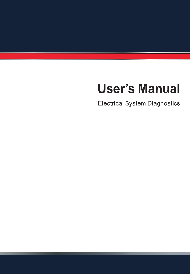
Press the Power Switch forward to activate the tip with a positive
voltage. The Red LED should light and the LCD display will read
the battery voltage. A beep tone will sound. Let go of the power
switch and the LED will turn off and the tone will cease.
2.4 General Description
2.5 Power
2.6 Quick Self-Test
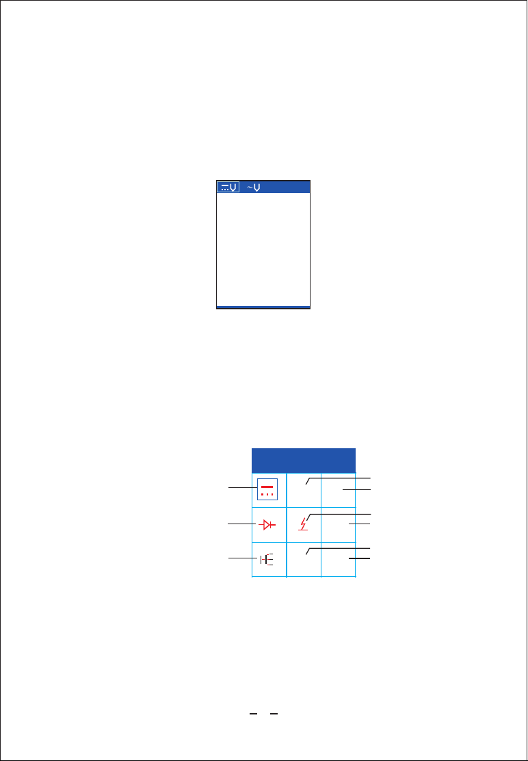
Determine at a glance if a circuit is positive, negative, or open
without having to reconnect clips from one battery pole to another.
Test for continuity with its built-in auxiliary ground lead.
By depressing the power switch, conduct a positive or negative
battery current to the probe tip for testing the function of an
electrical component without the use of jumper wires.
Test for poor ground contacts instantly without performing voltage
drop tests. The tool is also short-circuit protected; its internal
circuit breaker will trip if it becomes overloaded.
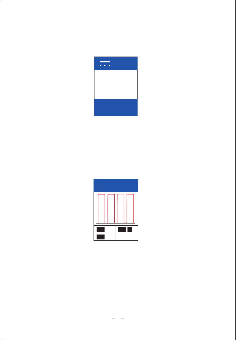
Follow and locate short circuits without wasting fuses. The tool’s
long cable allows you to test along the entire length of the
vehicle without constantly searching for suitable vehicle grounds.

5
IMPORTANT: When powering-up components, you can increase the
life of power switch in the tool if you first press the switch, then
contact the tip to the component. The arcing will take place at the tip
instead of the contacts of the switch.
Press the Power Switch rearward to activate the tip with a negative
voltage. The Green LED should light and the LCD display will read
the 0.0V (ground). A beep tone will sound. Let go of the power
switch and the LED will turn off and the tone will cease.Your tool
is working correctly and is now ready for use. (Figure 1)
Figure 1
The tool is short-circuit protected. Its internal circuit breaker will
trip if it becomes overloaded. The circuit breaker is a valuable test
tool as well as a safety measure to protect the tool from overload.
2.7 Auto Circuit Breaker

6
When circuit breaker tripped, the LCD will display as below.(Figure 2)
All other functions of the tool are still active, which means you can
still probe a circuit and observe the voltage reading. When the
circuit breaker is tripped, the tool will NOT be able to conduct
battery current to the tip even when the power switch is pressed.
Intentionally tripping the breaker and using the tool to probe can be
considered an added precaution against accidental pressing of the
power switch.
2.8 Work mode
Ω?
Figure 2
Auto Circuit
Breaker Break
Figure 3
YD 308
~
Ω
0-5
~HZ
P-N
①③
⑤
⑨
⑥
④
⑦⑧
②
When power on, the Main Menu displays (Figure 3). There are 9
functional modes to diagnose the electrical systems. You can select
the function icon by pressing UP / DOWN, LEFT/ RIGHT, and press
the MIDDLE button to enter the corresponding functional mode.
Press LEFT button to exit this mode and return to the Main Menu.
9 functions includes: DC Voltage, AC Voltage, Resistance, Diode
Testing, Power Supply Mode, Voltage Output Mode, Relay Testing,
AC Frequency, P-N Mode.

DC Voltage:
While in this mode, contact the probe tip to a circuit, LCD
displays the DC voltage 12.0V. (Figure 4)
Figure 4
AC Voltage:
While in this mode, contact the probe tip to a circuit, LCD displays the
Max. Voltage, the Min. voltage and frequency (Figure 5).
Figure 5
AC FREG
10.4
Max
0.0
Min
5.2 K
Freg HZ
Resistance:
While in this mode, contact the probe tip to a circuit, LCD displays
the resistance of the tip and auxiliary ground lead. (Figure 6)
7
VDC
12.1 V
TIP
VOL TAGE
12.0 12.1
MIN MAX V V

Figure 6
0HM
0268
Ω
Test the positive & negative of diode (figure 7)
Diode Testing:
DIODE
Forward Bias
(+) (-)
268.1
Figure 7
Power Supply Mode:
The mode includes three ways of power supply and safety electric
current setting.(figure 8)
POW SWITCH
18A
MOMENT
LATCH
PULSE
SETTING
Figure 8
8

Moment Mode:
Continuously press UP button, the probe tip output voltage.
Continuously press DOWN button, the probe tip contacts
ground. Release the button, it will be the normal mode. (Figure
9)
On
Off
↗
↗
Press Press
Figure 9
When the probe tip is in the status of power output, the red light
on.When the tip is in the status of ground, green light on. Otherwise,
the lights off .Contact the probe tip to a circuit, LCD will display the
voltage of the tip and auxiliary ground lead, current and
resistance.(Figure 10)
MOMENT
00.0V
00.0A
1K
Figure 10
LATCH Mode:
Press UP button, the probe tip outputs voltage. Press DOWN button,
the probe tip contacts ground. Press RIGHT button, it is normal
mode.(Figure 11)
9

On
Off
Press&
START
Press&
STOP
↗
↗
Release Release
1 sec 1 sec
1 sec
On
Off
↗
↗
Press&Press&
Release Release
START STOP
Figure 11
When the probe tip is in the status of power output, the red light
on.When the tip is in the status of ground, green light on. Otherwise,
the lights off .Contact the probe tip to a circuit, LCD will display the
voltage of the tip and auxiliary ground lead, current and resistance.
(Figure 12)
LATCH
11. 4v
0.22A
53.5
Figure 12
PULSE Mode:
Press UP button, normal mode for 1 second, voltage output for 1
second, then repeatedly. Press DOWN button, normal mode for 1
second, ground for 1 second, then repeatedly. (Figure 13)
Figure 13
10

Press RIGHT button, it is normal mode. When the probe tip is in the
status of power output, the red light on.When the tip is in the status of
ground, green light on. Otherwise, the lights off .Contact the probe tip
to a circuit, LCD will display the voltage of the tip and auxiliary
ground lead. (Figure 14)
PULSE
12. 0v
Figure 14
SETTING Mode:
Setting current protection from 2-18A.The device will disconnect
from the relay and exit from function menu once current is
overlarge.(Figure 15)
SETTING
16A
Figure 15
Voltage Supply:
While in this mode, you can set voltage output(0-5V, variable voltage
value 0.5V). (Figure 16)
VOLTS SUPPLY
VOLTS
VREF
2.5V
2.5V
Figure 15
11

Relay Test
While in this mode, you can test if the relay is fault. Function
initialization display (Figure 17)
RELAY TESTER
00.0 V
Figure 17
Relay Figure as below: (Figure 18)
87A NC
30 Feed
87 NO
86
85
Solenoid
↗
↗
Figure 18
5-Pin Relay: Connect the black line to #30 pin, green line to #87A
pin, red line to #87 pin, In this case, the green light on, and the red
light off (Figure 19). Then connect the probe tip to #85 pin, ground
line connect to #86 pin. In this case, press UP button, the green light
off and red light on (Figure 20). This shows the relay is good.
Otherwise, it's bad.
12

Figure 19
13
85
30
87
87A
86
No
contact
No contact

4-Pin Relay: connect the black line to #30 pin, red light to #87 pin, in
this case, the green light on and red light off. Then connect the probe
to #85 pin, ground line to #86 pin and press then UP button, green
light off and red light on. This shows the relay is good. Otherwise, it's
bad.
AC Frequency
While in the mode, connect the probe tip to a circuit, it can show the
frequency on the LCD quickly and precisely. ( Figure 21)
HZ FRQ CTR
0976 HZ
Figure 20
P--N
While in this mode, connect the probe tip to a circuit, the LCD
will display if it is ground line or not. If not, it will display the
voltage. (Figure 22)
P-N
Positive(+)
Negative(-)
ERROR
Figure 21
15

Figure 7
3. Test Applications
3.1 Voltage & Polarity Testing
While in the mode of AC voltage, connect the probe tip to positive
circuit, the red led light on, the LCD displays the voltage with 0.1V
resolution. Audio tone indicator sounds.
If the probe tip connects to negative circuit, the green led light on,
the LCD will display 0.1v voltage. Audio tone indicator sounds.
If the OPEN circuit, both LEDs off.(
igure
probe tip connects to F7)
16

While the tool is in Resistance mode, using the probe tip with chass
is ground or the auxiliary ground lead, continuity can be tested on
wires and components attached or disconnected from the vehicle’s
electrical system.
When the probe tip is contacting a good ground, the LCD will indicate
“0.0Ω” and green LED will be on. a beep tone will sound(Figure 9)
3.2 Continuity Testing
Figure 8
17

18
In other cases, the LCD only indicates the resistance value.(Figure 10)
If the resistance value is greater than 100kΩ, the LCD will show “0L”.
Figure 10
Figure 9
?
600
Ω
Ω

Ω?
max
min
12.3V
0.3V
Hz
freq
42.9k
19
Once you extract a DTC from the vehicle and realize that trouble-
shooting begins with some kind of sensor circuit, there is a quick
test you can perform to verify the code. Testing your sensor is easy
while using the tool.
For example, you suspect there is a problem with your M.A.P. ? sensor
circuit, then follow the procedure involved with testing this sensor:
There is also another way to prove continuity of connections to
ground or battery. Power up the connection using the power switch.
If the circuit breaker trips you know that you have a good solid
low resistance connection.
NOTE: You can use the probe tip to pierce the plastic insulation on
a wire. This means that you can test the circuit without disconnecting
anything.
3.3 Signal Circuit Testing
Set the tool in AC Voltage mode, using the probe tip with chassis
ground or the auxiliary ground lead.
Apply vacuum.
Connect vacuum pump to MAP sensor.
Release vacuum and observe the LCD readings.(Figure 11)
If the LCD readings are abnormal, there is a problem with this
sensor.
Contact the probe tip to the MAP sensor positive terminal and
observe the LCD readings which should be a sine wave in normal
condition.
Figure 11
Table of contents
Popular Test Equipment manuals by other brands

Agilent Technologies
Agilent Technologies 16197A Operation and service manual

Vermason
Vermason 225706 Installation, operation and maintenance

Berner
Berner Profi LCD Plus II operating instructions

Omega Engineering
Omega Engineering hot point CL900A Series user guide

Tektronix
Tektronix DPO7000 Series Quick start user manual

Tektronix
Tektronix MSO4000B Series user manual

Bosch
Bosch BSA 43 Series Original instructions

Extech Instruments
Extech Instruments 380260 user guide

Fluke
Fluke 9132A Service manual

Anritsu
Anritsu MT1000A Network Master Pro Operation manual

Triplett
Triplett TVR10G PRO user manual

Keysight Technologies
Keysight Technologies U3050BH11 User's and service guide