4
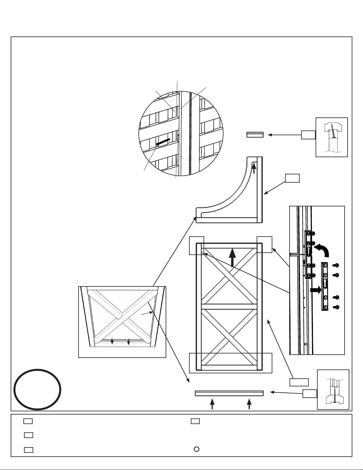
Step 1- Assemble Wings
1.RemovetheuppermetalconnectorsonbothsidesofPX2-TwoHighXPanel.Reattachthemetalconnectors
to PX2 by securing the bottom two holes of the metal connectors to the top two holes on PX2 so that the metal
connectors stick out from the top. Slide PA1 – Arch Topper between the two protruding metal connectors on
the top of PX2. Attach the metal connectors to the factory drilled holes in PA1. (Fig. 1A) *Ensure Panels are
orientedcorrectly!(Fig.1B)
x2
Fig. 1B - Filler Strips on Bottom
of Panel!
2. Secure panels with a S4 - 2
1/4”WoodScrewthelocation
indicated by the large arrow in
the direction of the arrow. When
pre-drilled holes are not available
use a 1/8” Drill Bit to drill holes on
an angle in the inside of the panel
as shown. (Fig. F)
3. Secure R-Top and Bottom Rails to
PanelAssemblywithS4-21/4”
Wood Screws locations indicated
by arrows in the direction of the
arrow. *R- Top and Bottom Rails
will overhang 1/4” on either
sideofpanel.ExceptonArch
Topper!!
* R- Top and Bottom Rails may
need to be cut to 20” (50.8cm)
and 7 1/4” (18.4cm)
(It is recommended to use a Mitre
Box or Mitre Saw)
4. Repeat until two panel assemblies
are created.
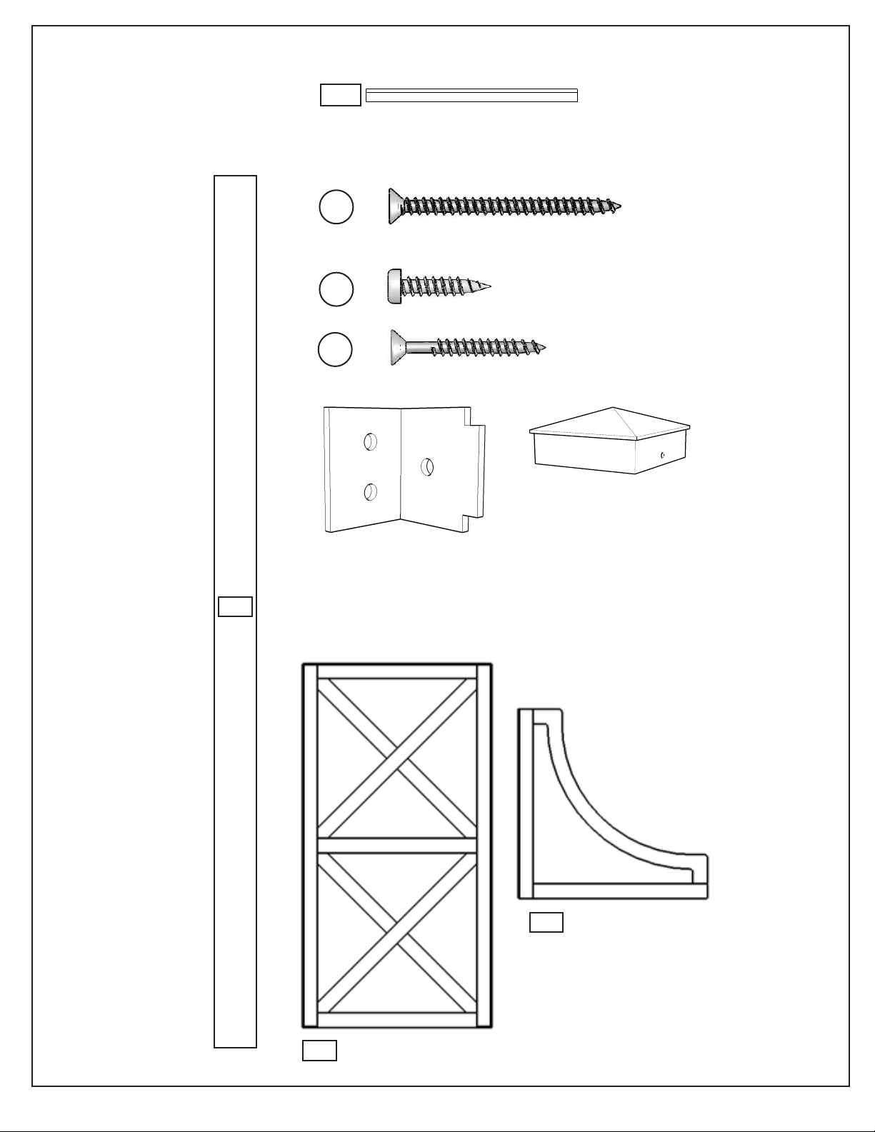
R
2x Arch Topper
2x Two High X Panel
2x Top & Bottom Rail At 20” (50.8cm)
2x Top & Bottom Rail At 7 1/4” (18.4cm)
8x #8- 2 1/4” Wood Screws
PA1
PX2
S4
Fig. 1A
Secure with Screws*. Use factory drilled holes.
Asegure el ensamblado usando tornillos*.
Use los agujeros pretaladrados.
Fixez l'assemblage au moyen de vis*. Servez-
vous des trous prépercés à l'usine.
empêche l'accumulation d'eau.
Note wood piece at bottom
prevents collection of water.
Note que la pieza de madera
inferior evita la acumulación de
agua.
Prenez note que la pièce en bois
située au bas de chaque
élément de l'assemblage
Do not remove Small Connector.
No retire los conectores
Ne retirez pas les petites pièces de
raccordement.
1Assemble Panels in the required orientation for your project.
*Hardware is provided with 2x2x62" post/rail.
Unir los paneles según la orientación necesaria para su proyecto.
l'usine.
supérieurs du panneau qui ont été percés à
A.
fixez-les de nouveau au moyen des deux trous
*Máximo 3 paneles de ancho x 3 paneles de alto.
*Se proporcionan los artículos de ferretería con los postes/travesaños de 2x2x62".
*Maximum 3 panel wide x 3 panel high.
*Le matériel est fourni avec 2x2x62" poste/barre.
*Le maximum 3 panneau x large 3 lambrisent haut.
Assembler Panneau dans l'orientation exigée pour votre projet.
Remove Large Connectors and reattach using
top two factory drilled holes on panel.
Retire los conectores grandes y vuelva a
instalarlos usando los dos agujeros
pretaladrados del panel.
Retirez les grandes pièces de raccordement et
Assemble Toppers to Panels if required.
Instale los topes en los paneles.
Assemblez les pièces supérieures et les panneaux dans l'orientation exigée pour votre projet.
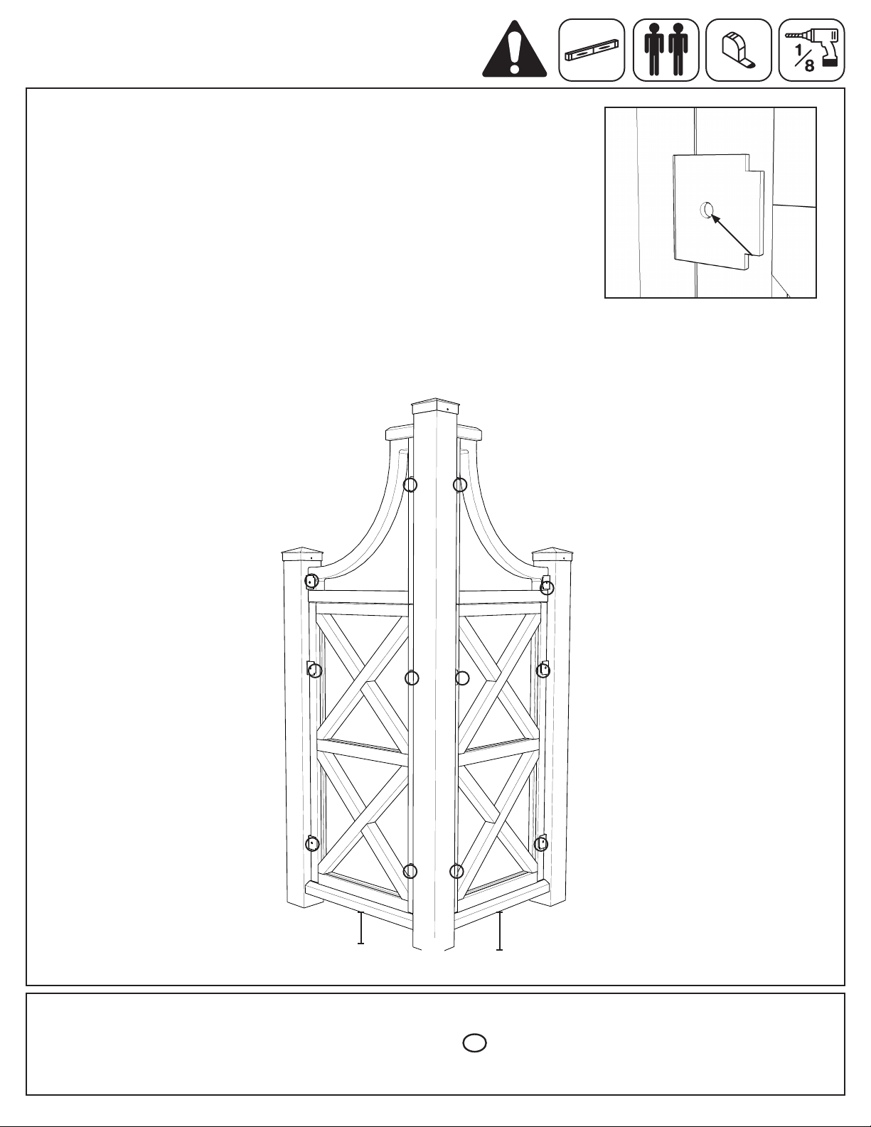
Note orientation of keyhole.
Tenga en cuenta la orientación
del agujero de la cerradura.
Notez l'orientation de l'encoche
en trou deserrure.
PX2
PA1
R
R
3. Connect last assembled panels to make a fence section.
Cut and attach Top and Bottom Rails.
Corte y fije los rieles superior e inferior.
Taillez et fixez la main courante ainsi que la lisse basse.
Insert male into female. Slide down until flush with adjacent panel.
Introduzca el extremo macho en el extremo hembra. Deslícelo hacia
abajo hasta que quede al ras del panel adyacente.
Insérez les pièces de raccordement mâles dans les pièces
de raccordement femelles. Faites glisser le panneau
vers le bas jusqu'à ce qu'il soit au même niveau que
le panneau adjacent.
Remove Large Connectors and reattach using top two
factory drilled holes on panel.
Retire los conectores grandes y vuelva a instalarlos
usando los dos agujeros pretaladrados del panel.
Retirez les grandes pièces de raccordement et fixez-les
de nouveau au moyen des deux trous
supérieurs du panneau qui ont été percés
à l'usine.
Note
orientation
of keyhole.
Tenga en cuenta
la orientación del
agujero de la
cerradura.
Notez l'orientation
de l'encoche en
trou de serrure.
Note que la pieza de madera inferior
evita la acumulación de agua.
Top and Bottom Rail will
overhang 1/4"on either side.
Attach Top with Screws*
through factory drilled holes.
On Bottom, space Screws*
4" from edges of panels.
Shown here are configurations using
a Topper. 2 and 3 High Panels can
also be connected together as
purchased.
*Use 2 1/4" stainless steel screws
included in the Panel Clip set to
secure and strengthen the assembly.
78
½"
59"
20" 20" 20" 20"
39
½"
39
½"
One Wide Ancho sencillo Une pièce de largeur
Four Wide Ancho cuádruple Quatre pièces de largeur
Three Wide Ancho triple Trois pièces de largeur
Two Wide Ancho doble Deux pièces de largeur
2
Assemble Panels side by side.
Conecte los paneles lado a lado.
Assemblez les panneaux côte à côte.
No retire los conectores
pequeños.
Note wood piece at bottom prevents
collection of water.
Prenez note que la pièce en bois
située au bas de chaque élément
de l'assemblage empêche
l'accumulation d'eau.
Secure with Screws*. Use factory drilled holes.
Ne retirez pas les petites pièces
de raccordement.
Do not remove Small Connectors.
Fixez l'assemblage au moyen de vis.* Servez-vous des trous prépercés à l'usine.
Asegure el ensamblado usando tornillos*. Use los agujeros pretaladrados.
Screws* are 2 1/4" stainless
steel included in Panel Clip set.
Los tornillos* son de acero inoxidable de 2 1/4"
y se incluyen en el juego de sujetadores de paneles.
*Les vis sont celles de 2-1/4 po en acier inoxydable qui sont fournies dans le nécessaire de fixations pour panneaux.
Basic Guidelines
for Panel Assembly
Las ilustraciones muestran
configuraciones con topes. También
se pueden conectar 2 y 3 paneles
altos a medida que se adquieran.
*Use los tornillos de acero inoxidable
de 2 1/4" que se incluyen en el juego
de sujetadores de paneles para
reforzar el ensamblado.
Pautas básicas para
el ensamblado de
los paneles Les assemblages illustrés comportent des
pièces supérieures. Il est possible
également d'assembler des panneaux
à deux ou à trois carreaux de hauteur
(vendus séparément).
*Utilisez les vis en acier inoxydable de
2-1/4 po fournies dans le nécessaire de
fixations pour panneaux afin de fixer et
de renforcer l'assemblage.
Instructions de base
pour l'assemblage
des panneaux
1Assemble Toppers to Panels.
Instale los topes en los paneles.
Assemblez les pièces supérieures
et les panneaux.
3
Los rieles superior e inferior sobresaldrán 1/4"
a cada lado. Fije el tope instalando tornillos*
en los agujeros pretaladrados. En la parte
inferior, deje un espacio de 4" entre los
tornillos* y los bordes de los paneles.
}
4"
}
4"
}
4"
}
4"
La main courante et la lisse basse seront
en surplomb de 1/4 po de chaque côté.
Fixez la main courante en insérant les vis*
dans les trous prépercés à l'usine. Au bas
des panneaux, laissez un espace de 4 po
entre les vis et les côtés des panneaux.
panel_cap_labels_19x9.5.indd 7 12/3/09 4:17:29 PM
R
Pilot holes to the right
B.
niveau que le panneau adjacent.
panneau vers le bas jusqu'à ce qu'il soit au même
pièces de raccordement femelles. Faites glisser le
Assemblez les panneaux côte à côte.
Conecte los paneles lado a lado.
Assemble Panels side by side. (Maximum 3 wide x 3 high)
Insérez les pièces de raccordement mâles dans les
Insert male into female. Slide down until flush with
adjacent panel.
Introduzca el extremo macho en el extremo hembra.
Deslícelo hacia abajo hasta que quede al ras del
panel adyacente.
*Les vis sons 2 1/4po
fourniers avec
poteau/Rail
2 x 2 x 62po.
C.
Screws* are 2 1/4"
included with
2x2x62" post/rail.
*Use los tornillos de
acero inoxidable
de 2 1/4" que se
incluyen en el
juego de
postes/travesaños
de 2x2x62".
Remove the male connectors from the outside of the
panel assembly.
Quite los conectores masculinos del exterior de la
asamblea de panel.
Enlever les connecteurs mâles de l'extérieur de
l'assemblée de panneau.
le connecteur
mâle court
connector
conector
masculino
short male
corto
male
connector
conector
masculino
connecteur
mâle
2 1/4” Screw
Drill Hole on an Angle
Thick Piece
of Wood
Skinny Piece
of Wood
Groove
Fig. F