
SPECIFIC SAFETY RULES
Do not tamper with the engine in an effort to get it to run at
higher speeds. The maximum engine speed is preset by the
manufacturer and is within safety limits. See engine manual.
Keep a Class B fire extinguisher on hand when operating this
machine in dry areas as a precautionary measure.
FUEL SAFETY
Fuel is highly flammable, and its vapors can explode if ignited.
Take precautions when using to reduce the chance of serious
personal injury.
When refilling or draining the fuel tank, use an approved fuel
storage container while in a clean, well-ventilated outdoor area.
While adding fuel or operating the unit, do not smoke, and stay
away from sparks, open ames, or other sources of ignition near
the area of operation. Never ll the fuel tank indoors.
To avoid sparking or arcing, keep grounded conductive objects
– such as tools – away from exposed, live electrical parts and
connections. These events could ignite fumes or vapors.
Always stop the engine and allow it to cool before lling the fuel
tank. Never remove the cap of the fuel tank or add fuel while the
engine is running or when the engine is hot. Do not operate the
machine with known leaks in the fuel system.
Loosen the fuel tank cap slowly to relieve any pressure in the tank.
Never overll the fuel tank. Because engine heat can cause fuel to
expand, never ll the tank to more than 1/2” below the bottom of
the ller neck. This will provide space for fuel expansion.
Replace all fuel tank and container caps securely and wipe up
spilled fuel. Never operate the unit without the fuel cap securely
in place.
Avoid creating a source of ignition for spilled fuel. If fuel is spilled,
do not attempt to start the engine. Instead, move the machine
away from the area of spillage and avoid creating any source of
ignition until fuel vapors have dissipated.
When fuel is spilled on yourself or your clothes, wash your skin
and change clothes immediately.
Store fuel in containers specifically designed and approved for
fuel storage.
Store fuel in a cool, well-ventilated area, safely away from sparks,
open ames, or other sources of ignition.
Never store fuel – or a machine with fuel in the tank – inside a
building where fumes may reach a spark, open ame, or any other
source of ignition (such as a water heater, furnace, or clothes
dryer). Allow the engine to cool before storing in any enclosure.
Thoroughly inspect the area to be worked. Keep the working area
clean and free of debris to prevent tripping. Operate on at, level
ground.
Never place any part of your body where it would be in danger if
movement should occur during assembly, installation, operation,
maintenance, repair, or relocation.
Keep all bystanders, children, and pets at least 75 feet (23m)
away. If you are approached, stop the unit immediately.
Do not mount anything on the hopper and never carry
passengers.
Never park the machine in a place with unstable ground that
could give way, particularly when it is full.
Disengage clutch lever before starting the engine.
Start the engine carefully according to instructions and with feet
away from the moving parts.
Never leave the operating position when the engine is running.
Always hold the unit with both hands when operating. Keep a
firm grip on the handlebars. Be aware that the machine may
unexpectedly bounce upward or jump forward if the machine
should strike buried obstacles such as large rocks or roots.
Walk, never run with the machine.
Do not overload the machine capacity. Always drive at a safe
speed, and adjust the speed to the slope of the land, the surface
conditions of the road, and the weight of the load.
Use extreme caution when in reverse or pulling the machine
towards you.
Exercise extreme caution when operating on or crossing gravel
drives, walks, or roads. Stay alert for hidden hazards or trafc.
On soft ground, drive at the first forward/reverse gear. Do not
rapidly accelerate, turn sharply or stop.
Pay the utmost attention when working on frozen ground, as the
machine may tend to skid.
Do not operate the machine in confined areas where there
may be a risk of crushing the operator between the machine
and another object.
Never operate the machine on slopes where angle is over 20°.
When operating on a slope, whether moving forward or in
reverse, always make certain that the weight is evenly balanced.
Always operate the machine straight up or down slopes, never
drive sideways or across the slope. Do not shift gears on slopes.
When dumping the contents of the hopper, the center of gravity
will change continuously and the ground conditions will be
essential for the stability of the machine. Use extra caution and
control when dumping the hopper on unstable ground, such as
wet clay or soil.
6
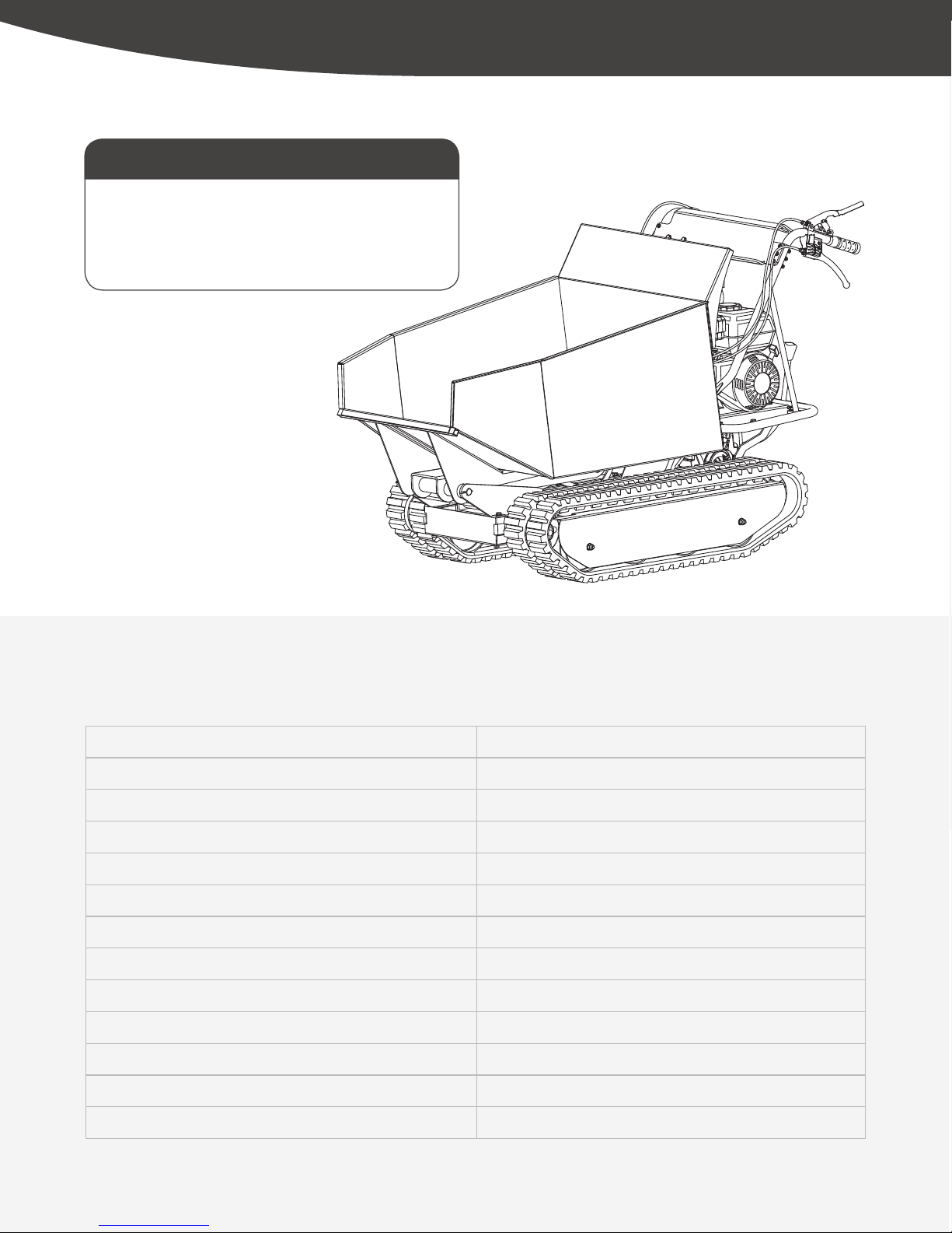
Power Trackbarrow
»
Operator’s Manual
YD8105PM04 - 1804 Safety
|


 Operator's manual")


