manuals.online logo
Brands
  1. Home
  2. •
  3. Brands
  4. •
  5. Yashica
  6. •
  7. Digital Camera
  8. •
  9. Yashica FX-3 Operating instructions

Yashica FX-3 Operating instructions

\^SHICA
FX-7
YASHICA
CO.,
LTD..TOKYO
Printed
in
Japan
5
Sa)
li^
=
D
0
(n
^
^
ASSEMBLING
CHART
[
[
[
[
[
r
L_-
[
[
[
[
[
[
[
[
[
[
[
[
[
TT
e->
-B:
>-
-
f\.
-
-
OJ
-
o.
-
-
-
0.
-
o
0
CO
•
cc
CfC
h
>-
C
CO
Ch
Ch
M
cc
CO
K
®
u
0
•
•
•
■
P
CO
'C
•0
u
®
c
c
M
<
CO
<
H
iH
C^i
•P
t-.
•H
o
CO
o
o
•P
u
Ch
CO
e>
p
o
a
a
4i
■
p
®
p
Q
•4->
C/J
p
CO
3
CO
(h
d
05
4^
■
p
CD
a
a
®
r-
(H
U
iH
K
«-(
«-(
P
P
o
®
a<
4<
o
0.
O
CO
a
CO
CO
T
p
P
>
OJ
P
P
cc
a
o
O
c
Q>
®
t/J
Vi
u
U
a
a
n
Fh
®
®
®
a
pL4
a
cS
CD
CD
c
®
®
■
p
■
P
•P
p
p
CO
OJ
m
W
tf
•p
■
P
P
iJ
CD
o:
o
Ch
c
3
o
u
P
u
•r^
•H
nH
p
P
P
o
o
P
P
CO
CO
CO
CO
s
a
a
CO
i/J
CO
l-l
p
CO
a
CVJ
M
p
-3
Prt
fVl
\t
oi
A
o
O
J>
o
A
M
rrs
sO
01
CVJ
o
-3
cr
-3
r-
-3-
•*-
N
\J
M
O
OJ
A
A
D
p-
\>
^J
Cr
^i)
J'
CA
a
O'
\D
sD
r—
T—
>
A
o
sD
O
■
c
^o
sO
A
A
(M
r'
p-
LA
0-
D
cr
O
OJ
-o
3
A
r*
-
--
--
w
w
®
®
p
p
®
a
CD
P
iH
iH
c
a
fX*
r
•
3
p
CO
P
®
®
p
•
CO
K
hf
bf
3
CO
O
U
U
a
®
a
a
a
P
P
P
Pi
p
o
o
P(
P
w
o
o
p
a
Ch
Pi
p<
3
p
p
f—1
rH
p
P
•H
CO
o
s
a
a
a
OJ
fA
(\J
01
o
o
A
r\
3-
o
A
o
CM
:vj
n
A
A
:>
T-
3
A
A
*“
A
OJ
fA
A
A
CM
■
M
OJ
OJ
>J
M
I
CM
O
P
(d
•H
CO
o
UOTE
:
(Parts
with
marked
"-Jt"
ere
not
Available)
NOTE
:
(Parts
with
marked
are
not
Available)
PARTS
NO.
_
DESCRIPT
IOtl
6617202U
E.
Rine
Removal
of
Top
and
Base
Covers
Removal
of
Base
Cover
Cautions:
There
are
possibilities
that
the
sprocket
lower
R
button
may
be
undone
because
the
adhesives
applied
to
it
lose
resistance
to
separation,
so
that
be
sure
not
to
miss
it.
Removal
of
Top
Cover
1.
Peel
off
the
W
lever
leather
(147660).
2.
Remove
the
W
lever
SS
(66001037),
and
take
off
the
W
lever
(147651)
and
the
lever
mount
(147652).
Cautions:
The
W
lever
SS
is
of
the
left-handed
screw.
3.
Remove
the
top
cover
nut
(147659).
Begin
removal
of
the
shutter
dial.
Set
the
shutter
dial
at
1/TOOO,
and
ASA
at
100,
then
start
the
following
work.
4.
Remove
the
name
plate
SS
(133298).
The
disassembling
procedure
is
as
illustrated
in
the
right
figure.
Name
plate
SS
(133298)
ASA100
shutter
1/1000
Shutter
dial
nameplate
(147415
ASA
name
plate
(133295)
ASA
spring
(147416)
Sdial
(147418)
ASA
color
(147409)
1
5.
Remove
the
rewind
knob
ass'y
(066920).
Cautions:
Use
the
root
of
the
tweezers
but
not
the
screw
driver
for
removing
the
rewind
shaft
fork.
6.
Take
off
the
top
cover
nut
(on
the
rewind
side)
(147659);
as
a
result,
the
rewind
shaft
cover
(147681)
will
be
removed.
7.
Remove
two
pieces
of
top
cover
SS'
(61915529)
(2)
and
(61903020)
(1),
respectively;
four
pieces
in
total.
8.
Gently
separate
the
top
cover
ass'y
(066920)
from
the
body.
Face
the
surface
of
the
mount
base
upward,
hold
the
top
cover
by
the
right-hand
,
and
remove
it
by
lightly
rolling.
9.
Disconnect
the
soldered
synchro
lead
wires
(black
and
light
brown)
inside
the
top
cover.
Removal
of
Front
Leather
1.
Peel
off
the
self-lever
leather
(147834).
2.
Remove
the
self
lever
SS
(66001027)
and
(132823).
3.
Peel
off
the
front
leather,
right
(147115)
and
the
front
leather,
left
(147116).
Removal
of
Shutter
Base
Plate
1.
Remove
2
shutter
base
plates
SS
(61914022)
and
a
lock
lever
shaft
(147816).
Z
Remove
the
solder
of
the
lead
wires,
yellow,
violet
and
gray.
3.
Remove
the
shutter
base
plate
(066445).
4.
The
shutter
shaft
is
removed.
(147422)
The
shutter
shaft
spring
is
removed.
(147423)
Shutter
speed
set
at
1
/1000
2
Removal
of
AMP
Ass'y
1.
Remove
the
solder
of
each
lead
wire.
2.
Remove
2
AMP
substrates
SS
(61912524).
3.
Remove
the
solder
of
5
legs
of
LED.
Removal
of
Mirror
Box
Ass'y
Yellow-—10
Orange
(Yellow)
Red
Brown
(Green)
Purple
Purple
Gray
1
.
Remove4
body
mount
SS
(131177)
and
body
mount
(147821).
Cautions:
(1)
The
standard
position
when
assembling:
At
the
back
cover
of
the
mount
ring,
the
insulating
collar
(132489)
is
made
to
agree
with
the
red
mark
put
on
the
mount
cover.
(2)
I
n
some
cases,
the
adjusting
washer
is
inserted
in
the
lower
side
of
the
mount
ring,
so
that
care
should
be
used
not
to
lose
the
washer.
2.
Remove
4
mount
covers
SS
(63913024)
and
a
mount
cover
(147801).
3.
Remove
3
mirror
boxes
SS
(61927024)
and
2
strap
holder
SS
(132143).
4.
While
lifting
AMP,
pull
out
the
mirror
box
ass'y
forward
and
remove
it.
Removal
of
Counter
Frame
1.
Remove
counter
reverse
lever
spring
(147870)
engaging
with
the
counter
gear
(1)
(139887).
2.
Remove
3
counter
base
plate
SS
(61913024)
and
take
it
out
upward
to
remove.
Removal
of
Shutter
Ass'y
1.
Remove
3
shutter
attachment
screws
(61924022).
(One
of
the
screws
is
tightened
through
the
back
cover.)
Z
Pull
out
the
shutter
ass'y
(147201).
Sector
Setting
(1)
Turn
the
setting
lever
clockwise
by
use
of
the
set
pin.
(Due
to
the
operation
of
the
winding
lever,
S
set-pin
on
the
body
side
pulls
the
set
pin.)
(2)
Turn
the
sector
setting
lever
counterclockwise
by
use
of
the
upper
pin
of
the
setting
lever.
(3)
The
sector
setting
lever
is
caught
by
the
pins
of
both
front
and
rear
sector
drive
arms
and
turns
them
clockwise.
When
both
drive
arms
turn,
the
sector
descends.
(4)
When
both
drive
arms
are
full
set,
the
front
and
rear
sector
stop
levers
plunge
into
the
drive
arms
so
that
the
latter'
return
is
stopped.
With
the
above
operations,
the
setting
of
the
sector
ends.
3
Faults
that
may
occur
The
stop
levers
do
not
plunge
into
the
arms.
Setting
failure;
(Due
to
short
setting,
or
moving
failure
of
the
stop
levers.)
In
this
event,
viewing
from
the
film
side,
the
rear
sector
returns
(ascends)
when
the
winding
lever
returns.
Setting
of
Drive
Cam
(1)
When
the
setting
lever
is
set
(rotated
clock¬
wise),
the
pin
pushes
the
setting
gear;
as
a
result,
tfie
latter
is
turned
clockwise.
(2)
The
setting
gear
rotates
the
gear
on
the
lower
side
of
the
drive
cam
with
which
the
setting
gear
engages,
and
then,
the
drive
cam
counter¬
clockwise.
(3)
When
the
gear
is
full
rotated,
the
release
lever
plunges
in
the
drive
cam,
and
then
it
stops.
Operation
of
Shutter
(1)
The
release
lever
is
pushed
down
by
MCL-7
of
the
mirror
box,
and
the
hook
is
separated
from
the
drive
cam.
(2)
The
drive
cam
rotates
clockwise
due
to
the
restoring
force
of
the
drive
spring,
and
the
pin
is
pushed
out
to
the
outside.
(3)
Rotate
clockwise
the
front
curtain
stop
lever
through
3
parts
from
the
pin
to
the
front
curtain
stop
lever
to
release
the
front
sector
drive
arm;
thus,
the
front
curtain
is
opened.
(4)
When;
the
drive
cam
hits
against
the
coupling
plate,
the
governor
works
and
the
coupling
plate
is
released.
(5)
The
dri\/e
cam
is
separated
from
the
coupling
plate,
the
setting
lever
turns
counterclockwise
and
swings
the
rear
curtain
stop
lever
clock¬
wise,
releasing
the
rear
sector
drive
arm.
(6)
The.
rear
curtain
advances
and
the
shutter
closes.
'
Drive
cam
4
Operation
of
Bulb
(1)
When
the
speed
change
gear
is
set
at
B,
the
convex
of
B
lever
is
set
to
the
concave
of
B
cam
below
the
gear.
(2)
When
depressing
the
release
button,
B
lever
descends
and
is
set
to
the
concave
of
B
cam
as
in
the
case
of
(1);
the
lever
descends
lower
than
other
shutter
speeds.
The
low
speed
governor
gear
is
locked
at
the
upper
side
of
B
lever.
(3)
The
mirror
box
works,
the
shutter
is
released,
the
drive
cam
rotates,
and
it
stops
when
hitting
against
the
coupling
plate.
(The
front
sector
advances
before
the
hit
against
the
coupling
plate.)
However,
as
the
low
speed
governor
is
locked
by
B
lever,
the
operation
stops
here.
(4)
When
lifting
(freeing)
the
release,
B
lever
ascends,
the
low
speed
governor
is
unlocked,
freed
and
comes
to
rotate,
then
the
coupling
plate
gradually
gets
away.
*
Other
operations
are
the
same
as
the
ordinary
ones.
Faults
that
may
occur
The
shutter
fails
to
close.
Because
of
the
flatness
of
B
lever
being
dis-
Bulb
skipping
satisfactory,
it
does
not
return.
(Change
the
release-position
by
SR
lever
(3)
below
the
body.
Change
the
bending
angle
of
the
hook
of
B
lever.)
Operation
of
setting
(1)
When
lowering
the
pin
of
the
sector
gear
to
which
the
timer
spring
is
applied,
the
release
lever
B
plunges
into
the
drive
cam.
(2)
The
timer
stop
lever
rotates
clockwise,
and
locks
the
governor
gear.
Operation
of
release
(1)
When
pushing
down
the
release
lever,
it
is
separated
from
the
drive
cam.
However,
because
the
release
lever
B
being
hooked,
the
drive
cam
does
not
rotate.
(2)
Further
push
the
release
lever,
and
the
timer
stop
lever
turns
counterclockwise,
so
that
the
governor
gear
being
freed,
it
rotates.
The
sector
gear
returns
clockwise,
too.
(3)
Push
down
the
release
lever
B
immediately
before
the
ending
of
return
of
the
sector
gear,
and
the
drive
cam
is
freed
and
rotates.
Release
lever
B
Timer
stop
lever
5
Sector
gear
Adjustment
of
Shutter
Adjustment
of
shutter
speed
The
drive
spring
engages
with
the
drive
spring
base;
yet
its
position
is
to
be
moved.
However,
the
shutter
speeds
change
in
the
same
tendency
from
high
speed
down
to
low
speed.
For
example,
sucit
defects
as
a
second
being
over
and
1/125
sec
being
under
cannot
be
repaired.
Adjustment
of
curtain
travel
The
tension
of
the
drive
spring
is
changed
by
turning
the
ratchet
cylinder
(by
use
of
a
minus
(—)
screw
driver).
This
repair
is
possible
only
in
the
case
of
the
shutter
single,
where
it
is
impossible
to
measure
shutter
speeds,
so
that
the
repair
must
be
carried
out
depending
on
intui¬
tion.
*
When
adjusting
the
curtain
travel,
be
sure
to
confirm
shutter
speeds.
Adjustment
of
curtain
travel
Operation
of
Shutter
Phenomenon
When
setting
the
shutter
at
1/1000
and
pressing
the
shutter
button,
the
upper
half
darkens
and
the
shutter
speed
becomes
fast.
The
front
curtain
travel
is
slow.
Cause
The
shutter
moquette
(147206)
enters
the
inside
of
the
shutter,
and
contacts
with
the
front
curtain
when
the
latter
works.
Although
the
cause
varies
with
individual
shutters,
troubles
occur
in
case
the
end
of
the
front
curtain
projects
0.1
to
0.2
from
the
frame
supporting
the
sector
at
front
and
back.
Reparing
tequnicues
and
method
of
confirmation
•
When
sticking
the
moquette
between
the
body
and
the
shutter,
stick
it
lightly
lest
it
should
be
pushed
in.
It
should
be
sticked
such
that
it
is
placed
as
close
to
the
body
side
as
possible
and
the
top
of
the
shutter
side
of
mold
plane
becomes
low.
•
Reparing
method
of
complete
products
Remove
the
base
cover
and
2
pieces
of
cell
case
SS,
pull
out
the
cell
cases,
raise
the
mold
plane
in
such
manner
as
peel
it
off
with
tweezers,
anJ
again
stick
the
moquette
while
lightly
holding
the
mold
plane
on
the
body
side.
As
leaving
it
as
it
is,
check
the
shutter
speed
and
then
carry
out
the
assembly.
Shutter
6
Composition
of
Circuits
The
circuit
composition
consists
of
4
components
as
shown
in
the
left
figure.
(1)
Information
(2)
Adjustment
(Quantity
of
light)
(3)
Output
(4)
1C
(Control)
Calculate
and
adjust
information
by
1C;
by
using
the
result
of
which
as
output,
LED
is
driven.
EC
switch
information
[light-SPD
~j
jpilm
speed
setting
—
I
j
ASA
variable
resistor
j
j
Aperture
setting
—
Aperturej
!
Variable
Resistor
(AVR)/''
•
✓
/
/
T-"
,
1C
Input
Output
1
LED
I
I
1
_
OVER
I
under]
Adjustment
j"
Semi-fixed
"j
I
resistor
[
■
L
_J
Role
of
Each
Circuit
(1/2)
_
_
A1:
Logarithmic-compress
the
photoelectric
current,
calculate
it
with
V^sA-
^he
result
of
which
is,
as
V2,
sent
to
A2.
Vreg:.
A
constant
voltage
of
1.25±0.15V
is
generated
independent
of
variation
of
a
voltage
(Vcc)
from
the
battery.
Ra2:
Adjust
the
voltage
per
EV
of
Rp
and
Rasa-
The
adjustment
should
be
made
to
hold
as
follows.
Vreg-VI
=226mV
A2:
Calculate
V2,
the
output
of
A1,
Vp,
the
input
of
apperture,
and
Vadj,
the
input
of
light
adjustment,
the
result
(V3)
of
which
is
sent
to
A/D
.
V3
indicates
a
change
of
approximately
30mV
per
EV.
Co:
Amplifier
for
the
battery
checker;
when
Vcc
becomes
lower
than
24V,
a
signal
is
sent
to
A/D
to
turn
off
the
current
of
LED
with
the
result
that
the
LED
is
not
lit.
A/D:
A
circuit
to
determine,
depending
on
the
voltage
of
V3
sent
from
A2,
whether
OVER,
APPRO¬
PRIATE
or
UNDER
of
LED
should
be
lit.
This
is
generally
called
A/D
conversion.
8
c
c
[
[
[
[
[
[
[
[
[
[
[
[
[
c
[
[
[
Ojseration
of
Counter
Phenomenon
The
film
counter
does
not
advance
when
making
the
winding
lever
operate,
and
the
latter
half
of
the
film
counter
slips.
(It
will
advance
while
pressing
the
back
cover.)
Cause
Although
the
counter
G-1
engages
the
counter
gear,
yet
the
former
slips
and
does
not
advance
because
the
counter
release
SP
is
soft
that
pushes
the
counter
G-1.
(In
case
the
spring
is
deformed
during
installation.)
Counter
release
lever
Reparing
technique
and
confirming
method
•
Check
whether
the
counter
release
lever
fully
operates
toward
the
counter
G-1,
and
if
the
former
is
deformed,
repair
the
defect
to
strengthen
the
force
of
the
spring
to
push
the
counter
G-1.
'•
First
put
the
part
of
spring
to
press
the
counter
G-1
against
the
latter,
and
place
the
spring
in
the
catch
of
the
counter
release
lever
and
next
put
the
spring
in
the
counter
release
lever
shaft
Counter
making
a
little
free
the
wound
portion
at
the
central
part
of
the
spring,
then
apply
the
hook
on
the
opposite
side
to
the
film
counter
base.
Phenomenon
One
operation
of
the
winding
lever
makes
an
advance
of
film
by
2
frames,
or
an
unstable
advance.
Cause
If
there
are
burrs,
scratches,
etc.
in
the
portion
where
the
counter
contacts
the
counter
gear,
the
feed
failure
takes
place.
1.
When
soldering
the
lead
wire,
the
counter
G-1
was
deformed.
2.
The
corner
was
injured
by
the
screw
driver,
etc,
3.
There
is
a
burr
made
in
the
course
of
work.
4.
There
are
a
scratch,
chip,
etc.
in
the
counter
gear.
Repairing
technique
and
Confirming
method
The
failure
in
feed
of
the
film
counter
should
visually
be
found.
1
to
2.
Replacement
of
parts.
3.
Scrape
off
burrs.
(Not
partially,
but
totally
scrape
them
off.)
4.
When
adjusting
the
A-gear
stopper,
the
screw
driver
is
apt
to
scratch
it.
If
it
is
scratched,
replace
the
counter
gear.
9
Adjustment
Ra2:
The
volume
to
determine
the
amount
of
change
per
EV
of
aperture
and
ASA.
Making
the
voltage
of
Vreg
—
VI
agree
with
226±lmV.
R3:
This
is
to
change
the
lighting
width
of
LED.
Fixed
resistance
is
soldered
to
it,
being
selected
in
the
range
from
6kohms
to
lOkohms.
Standard
value:
(1)
+
and
green
(•)
are
lit,
Abt,
0.8
EV
(2)
Only
green
(•)
is
lit.
Ditto
(3)
Green
{•)
and—are
lit
Ditto
The
standard
resistance
is
8.2
kohms;
however,
when
it
is
intended
to
expand
each
lighting
width,
the
resistance
is
decreased,
and
when
it
is
intended
to
narrow
the
width,
the
resistance
is
increased.
However,
it
impossible
to
expand
or
narrow
•
(green)
only.
Ral:
This
is
semi-fixed
resistance
for
adjusting
the
amount
of
light.
With
a
flat
light
source,
and
setting
aperture,
ASA
and
shutter
speed
as
properly
selected,
adjustment
should
be
made
so
that
only
green
LED
(•)
is
lit.
Repairing
Method
1.
Not
lit
(LED)
No
current
flows
to
AMP
due
to
contact
failure
of
EC
switch
or
disconnection
of
white
lead
wire.
2.
OVER
is
left
lit
(1)
The
voltage
of
RF
is
high,
the
sam
as
Vreg
without
any
change.
(Because
of
wiring
or
R2,
Ra2
or
D
is
out
of
order.)
(2)
The
voltage
of
Rasa
is
high,
the
same
as
Vreg
without
any
change.
(Because
of
the
same
as
above.)
(3)
Vadj
is
low.
(The
leg
of
C4
shorts
to
the
body.)
3.
UNDER
is
left
lit
With
respect
to
the
phenomenon,
reverse
to
para.
2.
Short
circuits
of
RF,
Rasa,
Ral,
etc,
including
failure
in
SPD.
4.
One
or
2
of
3
LED's
go
on
and
off,
but
the
remainder
do
not
go
on.
(1)
Disconnection
of
soldered
legs
of
LED.
(2)
Disconnection
of
R5
through
R7.
(3)
Defective
LED.
Apply
R-range
of
tester
to
(+)
and
LED
(—)
sides,
and
check
whether
LED's
are
lit.
5.
The
lighting
width
is
broad.
Make
R3
greater,
(8.2
kohms
to
10
kohms)
6.
The
lighting
width
of
Green
(•)
is
narrow.
Make
R3
less,
(8.2
kohms
to
5.6
kohms)
7.
GREEN
is
not
lit.
UNDER
is
lit
directly
from
OVER
passing
over
GREEN.
1C
is
defective,
and
AMP
should
be
replaced.
Winding
Mechanism
•
The
A-S'M-set
lever
under
the
body
moves
to
the
spool
side
by
means
of
the
winding
lever
(147651),
and
sets
the
shutter
and
the
mirror
at
the
same
time,
•
Using
cocking
arm
fixer
Ass'y
(066616),
the
winding
can
be
made
away
from
.the
set
cam
fixer
(147610)
together
with
SR
lock
lever
(147439)
until
the
winding
is
made
halfway.
The
external
circum¬
ference
of
the
set
cam
clamp
is
used
in
the
middle
of
winding
so
that
the
shutter
release
shaft
is
con¬
structed
so
as
for
the
release
not
to
descent
in
the
course
of
winding
operation.
•
The
A-gear
stopper
pluges
in
the
A-gear
about
0,2mm
immediately
before
the
winding
stops,
and
then
the
check
pawl
is
released
from
the
set
cam
plate.
Adjusting
method
of
A-gear
stopper
Rotate
the
A-gear
stopper
shaft
(eccentric
screw)
(147618)
to
create
an
allowance
of
0.2mm.
Adjusting
method
of
check
pawl
Loosen
the
screw
(61814024)
and
make
the
check
anti-rewind
claw
collar
(147637)
(eccentric
colar)
rotate
for
adjustment
10
Winding
Operation
Phenomenon
When
gently
returning
the
winding
lever,
it
stops
midway,
and
cannot
return
to
the
full.
Cause
Perform
the
winding
until
the
winding
lever
engages
the
check
anti-rewind
claw,
where
the
operation
of
the
lever
should
be
checked.
In
case
the
lever
does
not
smoothly
move:
1.
The
winding
lever
edges
up
to
the
projection
due
to
an
inclination
of
the
top
cover.
2.
No
upward
and
downward
plays
are
found
on
the
Winding
feeding
plate
ass'y
and
the
wi¬
nding
lever
base.
3.
The
clogging
of
the
holes
of
the
counter
gear
base
and
the
winding
feeding
plate
ass'y.
Repairing
technique
and
confirming
method
1.
Install
the
top
cover
such
that
it
is
located
at
the
central
part
of
the
winding
lever.
2.
Regarding
paragraphs
2
and
3,
check
the
shaft
or
base
for
dimensions,
and
replace
one
of
them
which
is
not
acceptable.
Note:
Check
the
counter
for
advance,
return,
etc.
Faults
that
may
occur
The
winding
lever
fails
to
return.
Top
cover
nut
winding
feeding
plate
ass'y
Phenomenon
When
operating
the
winding
lever
all
the
way,
it
comes
to
be
out
of
order,
so
that
it
does
not
return
by
use
of
spring
tension.
Cause
Because
the
check
anti-rewind
claw
fails
to
free
from
the
set
cam
plate
when
operating
the
winding
lever
for
winding.
Repairing
technique
and
confirming
method
Remove
the
bottom
cover,
a
little
loosen
the
check
anti-rewind
claw
caller
SS,
make
the
ec¬
centric
check
anti-rewind
claw
caller
rotate,
and
tighten
the
check
anti-rewind
claw
caller
SS
while
fixing
the
slotting
part.
The
above
operation
should
be
repeated
until
a
perfect
o-
peration
is
obtained.
n

This manual suits for next models

1

Other Yashica Digital Camera manuals

Yashica 44A User manual

Yashica

Yashica 44A User manual

Yashica Electro 35 AF-mini User manual

Yashica

Yashica Electro 35 AF-mini User manual

Yashica Lynx-14E User manual

Yashica

Yashica Lynx-14E User manual

Yashica 635 User manual

Yashica

Yashica 635 User manual

Yashica Yashicaflex S User manual

Yashica

Yashica Yashicaflex S User manual

Yashica ELECTRO 35 MC User manual

Yashica

Yashica ELECTRO 35 MC User manual

Yashica J-5 User manual

Yashica

Yashica J-5 User manual

Yashica ATORON ELECTRO User manual

Yashica

Yashica ATORON ELECTRO User manual

Yashica MAT-LM User manual

Yashica

Yashica MAT-LM User manual
Yashica Electro 35 AF-mini User manual

Yashica

Yashica Electro 35 AF-mini User manual

Yashica TL Electro User manual

Yashica

Yashica TL Electro User manual

Yashica 8T2 User manual

Yashica

Yashica 8T2 User manual

Yashica APW-10 Operating instructions

Yashica

Yashica APW-10 Operating instructions
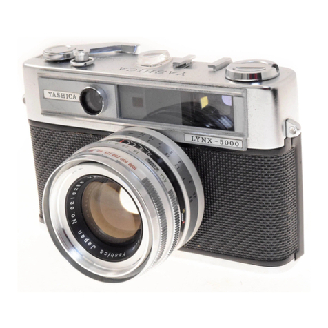
Yashica Lynx-5000 User manual

Yashica

Yashica Lynx-5000 User manual

Yashica MAT-LM User manual

Yashica

Yashica MAT-LM User manual

Yashica ELECTRO AX User manual

Yashica

Yashica ELECTRO AX User manual
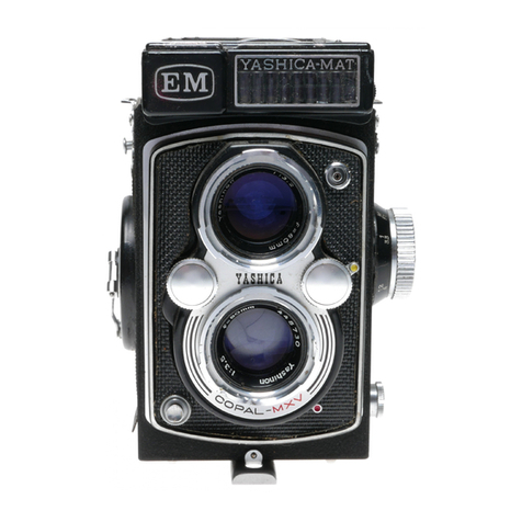
Yashica MAT EM User manual

Yashica

Yashica MAT EM User manual

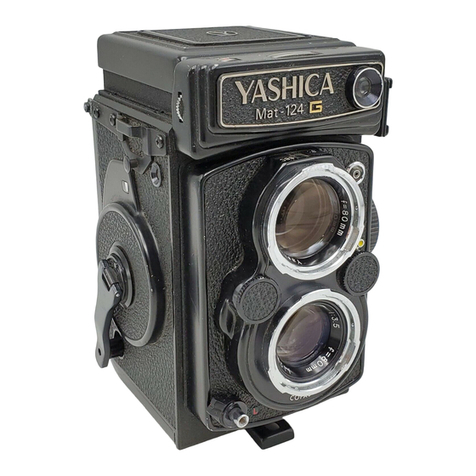
Yashica MAT-124G User manual

Yashica

Yashica MAT-124G User manual
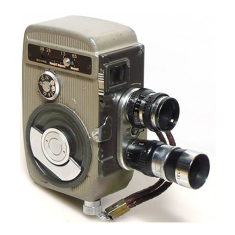
Yashica Pentamatic F1.8 User manual

Yashica

Yashica Pentamatic F1.8 User manual
Popular Digital Camera manuals by other brands

Photron FASTCAM ultima SE user manual

Photron

Photron FASTCAM ultima SE user manual

FujiFilm FinePix E550 quick start guide

FujiFilm

FujiFilm FinePix E550 quick start guide

Schäfter+Kirchhoff SK2048MVSH instruction manual

Schäfter+Kirchhoff

Schäfter+Kirchhoff SK2048MVSH instruction manual

ALFAtron ALF-20X-BC user manual

ALFAtron

ALFAtron ALF-20X-BC user manual

Miranda Sensomat instructions

Miranda

Miranda Sensomat instructions

Reconyx HYPERFIRE 2 HS2X manual

Reconyx

Reconyx HYPERFIRE 2 HS2X manual

TrueLife NannyCam R360 Instructions for use

TrueLife

TrueLife NannyCam R360 Instructions for use

AgfaPhoto Photo DC-8338i Specifications

AgfaPhoto

AgfaPhoto Photo DC-8338i Specifications

Sony Cyber-shot DSC-S600 Specifications

Sony

Sony Cyber-shot DSC-S600 Specifications

Polaroid FUN FLASH 820 quick start guide

Polaroid

Polaroid FUN FLASH 820 quick start guide

Steren Smart Home CCTV-218 instruction manual

Steren

Steren Smart Home CCTV-218 instruction manual

Olympus E420 - Evolt 10MP Digital SLR Camera quick start guide

Olympus

Olympus E420 - Evolt 10MP Digital SLR Camera quick start guide

GE POWER series E1480W Manual do utilizador

GE

GE POWER series E1480W Manual do utilizador

Motorola solutions edesix VIDEOBADGE VB-400 Setup guide

Motorola solutions

Motorola solutions edesix VIDEOBADGE VB-400 Setup guide

Panasonic Lumix DMC-TZ60 Basic operating instructions

Panasonic

Panasonic Lumix DMC-TZ60 Basic operating instructions

Panasonic Lumix DMC-FX7 operating instructions

Panasonic

Panasonic Lumix DMC-FX7 operating instructions

Minolta Maxxum 9000 owner's manual

Minolta

Minolta Maxxum 9000 owner's manual

Teledyne Princeton Instruments Nano-XF System manual

Teledyne

Teledyne Princeton Instruments Nano-XF System manual

manuals.online logo
manuals.online logoBrands
  • About & Mission
  • Contact us
  • Privacy Policy
  • Terms and Conditions

Copyright 2025 Manuals.Online. All Rights Reserved.