manuals.online logo
Brands
  1. Home
  2. •
  3. Brands
  4. •
  5. YASKAWA
  6. •
  7. Inverter
  8. •
  9. YASKAWA VS MINI J7 User manual

YASKAWA VS MINI J7 User manual

VS mini J7 Series
Instruction Manual
COMPACT GENERAL-PURPOSE INVERTER
VOLTAGE VECTOR CONTROL)
2
PREFACE
YASKAWA’s VS mini J7 is a compact and simple
inverter that is as easy to use as a contactor. This
instruction manual describes installation, maintenance,
inspection, troubleshooting, and specifications of the
VS mini J7. Read this instruction manual thoroughly
before operation.
YASKAWA ELECTRIC CORPORATION
General Precautions
• Some drawings in this manual are shown with the protective covers and shields
removed, in order to illustrate detail with more clarity. Make sure all covers and
shields are replaced before operating this product.
• This manual may be modified when necessary to reflect improvements to the
product, or changes in specifications.
Such modifications are denoted by a revised manual No.
• To order a copy of this manual, contact your Y SK W representative.
• Y SK W is not responsible for any modification of the product made by the
user. ny modifications will void the warranty.
3
CONTENTS
NOTES FOR SAFE OPERATION. . . . . . . . . . . . . . . . . . . . . 5
1. RECEIVING . . . . . . . . . . . . . . . . . . . . . . . . . . . . . . . . . . 12
•Checking the Name Plate . . . . . . . . . . . . . . . . . . . . . . . . . . . 12
2. IDENTIFYING THE PARTS . . . . . . . . . . . . . . . . . . . . . . 13
3. SPECIFICATIONS . . . . . . . . . . . . . . . . . . . . . . . . . . . . . 15
•Standard Specifications 200V Class) . . . . . . . . . . . . . . . . . . 15
•Standard Specifications 400V Class) . . . . . . . . . . . . . . . . . . 18
•Standard Wiring. . . . . . . . . . . . . . . . . . . . . . . . . . . . . . . . . . . 21
•Dimensions . . . . . . . . . . . . . . . . . . . . . . . . . . . . . . . . . . . . . . 23
•Parameters List . . . . . . . . . . . . . . . . . . . . . . . . . . . . . . . . . . . 25
4. MOUNTING. . . . . . . . . . . . . . . . . . . . . . . . . . . . . . . . . . . 35
•Choosing a Location to Mount the Inverter . . . . . . . . . . . . . . 35
•Mounting Dimensions . . . . . . . . . . . . . . . . . . . . . . . . . . . . . . 36
•Mounting/Removing Components . . . . . . . . . . . . . . . . . . . . . 37
5. WIRING. . . . . . . . . . . . . . . . . . . . . . . . . . . . . . . . . . . . . . 39
•Wiring Instructions . . . . . . . . . . . . . . . . . . . . . . . . . . . . . . . . . 39
•Wire and Terminal Screw Sizes . . . . . . . . . . . . . . . . . . . . . . 39
•Wiring the Main Circuit . . . . . . . . . . . . . . . . . . . . . . . . . . . . . 42
•Recommended Peripheral Devices . . . . . . . . . . . . . . . . . . . . 43
•Wiring the Control Circuit. . . . . . . . . . . . . . . . . . . . . . . . . . . . 45
•Wiring Inspection . . . . . . . . . . . . . . . . . . . . . . . . . . . . . . . . . . 46
6. OPERATING THE INVERTER . . . . . . . . . . . . . . . . . . . . 47
•Test Run . . . . . . . . . . . . . . . . . . . . . . . . . . . . . . . . . . . . . . . . 47
•Operating the Digital Operator. . . . . . . . . . . . . . . . . . . . . . . . 49
•LED Description. . . . . . . . . . . . . . . . . . . . . . . . . . . . . . . . . . . 51
•Simple Data Setting. . . . . . . . . . . . . . . . . . . . . . . . . . . . . . . . 55
4
7. PROGRAMMING FEATURES . . . . . . . . . . . . . . . . . . . . 57
•Parameter Set-up and Initialization . . . . . . . . . . . . . . . . . . . .57
•Setting V/f pattern . . . . . . . . . . . . . . . . . . . . . . . . . . . . . . . . . 58
•Switching LOCAL/REMOTE Modes . . . . . . . . . . . . . . . . . . . 61
•Selecting Run/Stop Commands. . . . . . . . . . . . . . . . . . . . . . .62
•Selecting Frequency Reference . . . . . . . . . . . . . . . . . . . . . . 63
•Setting Operation Condition . . . . . . . . . . . . . . . . . . . . . . . . .65
•Selecting Stopping Method . . . . . . . . . . . . . . . . . . . . . . . . . .82
•Building Interface Circuits with External Devices. . . . . . . . . . 84
•Setting Frequency by Current Reference Input . . . . . . . . . . . 89
•Decreasing Motor Speed Fluctuation . . . . . . . . . . . . . . . . . . 93
•Motor Protection . . . . . . . . . . . . . . . . . . . . . . . . . . . . . . . . . . 94
•Selecting Cooling Fan Operation. . . . . . . . . . . . . . . . . . . . . .96
•Using MEMOBUS MODBUS) Communications
when option card is installed). . . . . . . . . . . . . . . . . . . . . . .96
8. MAINTENANCE AND INSPECTION . . . . . . . . . . . . . . . 99
•Periodical Inspection . . . . . . . . . . . . . . . . . . . . . . . . . . . . . . .99
•Part Replacement . . . . . . . . . . . . . . . . . . . . . . . . . . . . . . . . . 99
9. FAULT DIAGNOSIS AND CORRECTIVE ACTIONS. . 103
APPENDIX . . . . . . . . . . . . . . . . . . . . . . . . . . . . . . . . . . . . 111
•CE Conformance . . . . . . . . . . . . . . . . . . . . . . . . . . . . . . . . . 111
5
NOTES FOR SAFE OPERATION
Read this instruction manual thoroughly before installation, operation, maintenance or
inspection of the VS mini. In this manual, NOTES FOR S FE OPER TION are
classified as “W RNING” or “C UTION”.
Indicates a potentially hazardous situation which, if not avoided, could result in death
or serious injury to personnel.
Indicates a potentially hazardous situation which, may result in minor or moderate
injury to personnel, and possible damage to equipment if not avoided. It may also be
used to alert against unsafe practices.
Items described in may also result in a vital accident in some situations. In
either case, follow these important notes.
RECEIVING
WARNING
CAUTION
These are steps to be taken to ensure proper operation.
CAUTION
(Ref. page)
• Do not install or operate any inverter which is damaged or
has missing parts.
Failure to observe this caution may result in personal injury or
equipment damage . . . . . . . . . . . . . . . . . . . . . . . . . . . . . . . . . . . . . . . . . . . . . . 12
CAUTION
6
MOUNTING
WIRING
CAUTION
(Ref. page)
• Lift the inverter by the cooling fin. When moving the unit, never
lift by the plastic case or the terminal covers.
Failure to observe this caution may cause the unit to be dropped resulting in
damage to the unit. . . . . . . . . . . . . . . . . . . . . . . . . . . . . . . . . . . . . . . . . . . . . . . 13
• Mount the inverter on nonflammable material i.e., metal).
Failure to observe this caution can result in a fire. . . . . . . . . . . . . . . . . . . . . . . 13
• When mounting open chassis in an enclosure, install a fan
or other cooling device to keep the intake air temperature
below 122°F 50°C).
Overheating may cause a fire or damage to the unit. . . . . . . . . . . . . . . . . . . . . 35
• The VS mini J7 generates heat. For effective cooling, mount it
vertically.
Refer to the figure in “Mounting Dimensions” on page 16.
WARNING
(Ref. page)
• Start wiring only after verifying that the power supply
is turned OFF for at least one minute, and all LED’s and
change LED’s are extinguished.
Failure to observe this warning can result in electric shock
or fire. . . . . . . . . . . . . . . . . . . . . . . . . . . . . . . . . . . . . . . . . . . . . . . . . . . . . . . . . 39
• Wiring should be performed only by qualified personnel.
Failure to observe this warning can result in electric shock
or fire. . . . . . . . . . . . . . . . . . . . . . . . . . . . . . . . . . . . . . . . . . . . . . . . . . . . . . . . . 39
• When wiring the emergency stop circuit, check the wiring
thoroughly before operation.
Failure to observe this warning can result in personal injury. . . . . . . . . . . . . . 39
7
WARNING
(Ref. page)
• For 400V class, make sure to ground the supply neutral.
• Make sure to ground the ground terminal according to the
local ground code.
Failure to observe this warning can result in electric shock
or fire. . . . . . . . . . . . . . . . . . . . . . . . . . . . . . . . . . . . . . . . . . . . . . . . . . . . . . . . . 39
CAUTION
(Ref. page)
• Verify that the inverter rated voltage coincides with the
AC power supply voltage.
Failure to observe this caution can result in personal injury
or fire.
• Do not perform a withstand voltage test of the inverter.
It may cause semi-conductor elements to be damaged.
• Make sure to tighten terminal screws of the main circuit
and the control circuit.
Failure to observe this caution can result in a malfunction,
damage or a fire. . . . . . . . . . . . . . . . . . . . . . . . . . . . . . . . . . . . . . . . . . . . . . . . . 42
• Never connect the AC main circuit power supply to output
terminals U, V and W.
The inverter will be damaged and void the warranty. . . . . . . . . . . . . . . . . . . . 42
• Do not connect or disconnect wires or connectors while
power is applied to the circuit.
Failure to observe this caution can result in personal injury.
• Do not change signal/control wiring during operation.
The machine or the inverter may be damaged.
8
OPERATION
WARNING
(Ref. page)
• Only turn ON the input power supply after replacing the
digital operator or optional blank cover.
Do not remove the digital operator or the covers while
current is flowing.
Failure to observe this warning can result in electric shock.
• Never operate the digital operator or dip switches when
your hand is wet.
Failure to observe this warning can result in electric shock.
• Never touch the terminals while current is flowing, even
when the inverter is stopped.
Failure to observe this warning can result in electric shock.
• When the fault retry function is selected, stand clear of
the inverter or the load. It may restart unexpectedly
after being stopped.
(Construct machine system, so as to assure safety for personnel,
even if the inverter should restart.) Failure to observe this
warning can result in personal injury.. . . . . . . . . . . . . . . . . . . . . . . . . . . . . . . . 75
• When continuous operation after power recovery is selected,
stand clear of the inverter or the load. It may restart
unexpectedly after being stopped.
(Construct machine system, so as to assure safety for personnel,
even if the inverter should restart.) Failure to observe this
warning can result in personal injury.. . . . . . . . . . . . . . . . . . . . . . . . . . . . . . . . 70
• Since the digital operator stop button can be disabled by a
parameter setting, install a separate external emergency stop switch.
Failure to observe this warning can result in personal injury.
• If an alarm is reset with the operation signal ON, the inverter
restarts automatically. Only reset the alarm after verifying that
the operation signal is OFF.
Failure to observe this warning can result in personal injury. . . . . . . . . . . . . . 46
9
MAINTENANCE AND INSPECTION
CAUTION
(Ref. page)
• Never touch the heatsink or braking resistor, the
temperature is very high.
Failure to observe this caution can result in harmful burns
to the body.
• Since it is easy to change operation speed from low to
high speed, verify the safe working range of the motor
and machine before operation.
Failure to observe this caution can result in personal injury
and machine damage.
• Install a holding brake separately if necessary.
Failure to observe this caution can result in personal injury.
• Do not change signals during operation.
The machine or the inverter may be damaged.
• All the parameters of the inverter have been preset at
the factory. Do not change the settings unnecessarily.
The inverter may be damaged. . . . . . . . . . . . . . . . . . . . . . . . . . . . . . . . . . . . . . 25
WARNING
(Ref. page)
• Never touch high-voltage terminals in the inverter.
Failure to observe this warning can result in an electrical shock. . . . . . . . . . . 99
• Disconnect all power before performing maintenance or
inspection. Then wait at least one minute after the power
supply is disconnected and all LEDs and CHARGE LED
are extinguished.
The capacitors discharge slowly, and may be dangerous. . . . . . . . . . . . . . . . . 99
10
Others
WARNING
(Ref. page)
• Do not perform a voltage withstand test on any part of
the VS mini J7.
This electronic equipment uses semiconductors and it is vulnerable
to high voltage. . . . . . . . . . . . . . . . . . . . . . . . . . . . . . . . . . . . . . . . . . . . . . . . . . 99
• Only authorized personnel should perform
maintenance, inspections or parts replacement.
[Remove all metal objects (watches, bracelets, etc.) before operation.]
(Use tools which are insulated against electrical shock.)
Failure to observe this warning can result in an electrical shock. . . . . . . . . . . 99
CAUTION
(Ref. page)
• The control PC board employs CMOS ICs.
Do not touch the CMOS elements.
They are easily damaged by static electricity.
• Do not connect or disconnect wires, digital operator,
connectors, or cooling fan while power is applied to the circuit.
Failure to observe this caution can result in personal injury. . . . . . . . . . . . . . . 99
WARNING
(Ref. page)
• Never modify the product.
Failure to observe this warning can result in an electrical shock or
personal injury and will void the warranty.
11
WARNING LABEL
warning label is displayed on the front cover of the inverter, as shown below. Follow
these instructions when handling the inverter.
PLASTIC ENCLOSURE
NAME-
PLATE
STATUS
INDICATOR
LAMP
WARNING
Warning Label
• Read manual before installing.
• Wait 1 minute for capacitor discharge after
disconnecting power supply.
• To conform to CE requirements make sure to
ground the supply neutral for 400V class.
.
LABEL
12
1. RECEIVING
fter unpacking the VS mini J7, check the following:
• Verify that the part numbers match your purchase order or packing slip.
• Check the unit for physical damage that may have occurred during shipping.
If any part of VS mini J7 is missing or damaged, call for service immediately.
•Checking the Nameplate
U.S. and Canadian Safety Standards for Types of 3-phase, 200V C,
0.13HP (0.1kW)
Example of 3-phase, 220V C, 0.13 (0.1kW)
13
2. IDENTIFYING THE P RTS
14
Notes
15
3. Specifications
•Standard Specifications (200V Class)
Voltage Class 200V single- / 3-phase
Model
CIMR-J7AU!!!!
3-phase 20P1 20P2 20P4 20P7 21P5 22P2 23P7
Single-phase B0P1 B0P2 B0P4 B0P7 B1P5 - -
Max. Applicable Motor Output HP kW)†0.13
0.1)
0.25
0.2)
0.5
0.4)
1
0.75)
2
1.5)
3
2.2)
5
3.7)
Output
Characteristics
Inverter Capacity kVA) 0.3 0.6 1.1 1.9 3.0 4.2 6.7
Rated Output Current A) 0.8 1.6 3 5 8 11 17.5
Max. Output Voltage V)
3-phase output only)
3-phase models, 200 to 230V proportional to input voltage)
Single-phase models, 200 to 240V proportional to input
voltage)
Max. Output Frequency Hz) 400 Hz Programmable)
Power
Supply
Rated Input Voltage and
Frequency
3-phase, 200 to 230V, 50/60Hz
Single-phase, 200 to 240V, 50/60Hz
Allowable Voltage Fluctuation -15 to +10%
Allowable Frequency Fluctuation ±5%
Control Characteristics
Control Method Sine wave PWM V/f control)
Frequency Control Range 0.1 to 400Hz
Frequency Accuracy
Temperature Change)
Digital reference: ±0.01% -10 to +50°C)
Analog reference: ±0.5% 25±10°C)
Frequency Setting Resolution
Digital reference: 0.1Hz less than 100Hz) / 1Hz 100Hz or
more)
Analog reference: 1 / 1000 of max. output frequency
Output Frequency Resolution 0.01Hz
Overload Capacity 150% rated output current for one minute
Frequency Reference Signal 0 to 10VDC 20kΩ), 4 to 20mA 250Ω), 0 to 20mA 250Ω)
Frequency setting volume Selectable)
Accel/Decel Time 0.1 to 999sec.
accel/decel time are independently programmed)
Braking Torque
Short-term average deceleration torque‡
0.13HP, 0.25HP 0.1, 0.25kW): 150%
0.5HP, 1HP 0.55, 1.1kW): 100%
2HP 1.5kW): 50%
3HP 2.2kW) or more: 20%
Continuous regenerative torque: Approx. 20%
V/f Characteristics Possible to program any V/f pattern
†Based on a standard 4-pole motor for max. applicable motor output.
‡Shows deceleration torque for uncoupled motor decelerating from 60Hz with the shortest possible
deceleration time.
16
Protective Functions
Motor Overload Protection Electronic thermal overload relay
Instantaneous Overcurrent Motor coasts to a stop at approx. 200% of inverter rated
current
Overload Motor coasts to a stop after 1 minute at 150% of inverter rated
output current
Overvoltage Motor coasts to a stop if DC bus voltage exceed 410V
Undervoltage Stops when DC bus voltage is approx. 200V or less approx.
160V or less for single-phase series)
Momentary Power Loss
Following items are selectable: Not provided stops if power
loss is 15ms or longer), continuous operation if power loss is
approx. 0.5s or shorter, continuous operation
Cooling Fin Overheat Protected by electronic circuit
Stall Prevention Level Individual levels during accel/running, enable/disable provided
during deceleration
Cooling Fan Fault Protected by electronic circuit fan stalling detection)
Ground Fault Protected by electronic circuit rated output current level)
Other Functions
Power Charge Indication
RUN lamp stays ON or digital operator LED stays ON.
Charge LED is provided for 400V)
ON until the DC bus voltage becomes 50V or less.
Input Signals
Multi-function Input
Four of the following input signals are selectable: Reverse run
3-wire sequence), fault reset, external fault NO/NC contact
input), multi-step speed operation, Jog command, accel/decel
time select, external baseblock NO/NC contact input), speed
search command, accel/decel hold command, LOCAL/
REMOTE selection, communication/control circuit terminal
selection, emergency stop fault emergency stop alarm
Output Signals
Multi-function Output
Following output signals are selectable 1 NO/NC contact
output):
Fault, running, zero speed, at frequency, frequency detection
output frequency ≤ or ≥ set value), during over torque
detection, minor error, during baseblock, operation mode,
inverter run ready, during fault retry, during UV, during speed
search, during speed search, data output through
communication
Standard Functions
Full-range automatic torque boost, slip compensation, DC
injection braking current/time at start/stop frequency reference
bias/gain, [MEMOBUS communications RS-485/422, max.
19.2K bps).]
Voltage Class 200V single- / 3-phase
Model
CIMR-J7AU!!!!
3-phase 20P1 20P2 20P4 20P7 21P5 22P2 23P7
Single-phase B0P1 B0P2 B0P4 B0P7 B1P5 - -
17
Other Functions
Display
Status Indicator LED RUN and ALARM provided as standard LED’s
Digital Operator
JVOP-140)
Available to monitor frequency reference, output frequency,
output current. 3 character, 7 segment LED Display.
Terminals Main circuit: screw terminals
Control circuit: plug-in screw terminal
Wiring Distance between
Inverter and Motor 328ft 100m) or less‡
Enclosure Open chassis
Cooling Method Cooling fan is provided for 200V, 0.75kW 3-phase), 400V,
1.5kW single-phase), others are self-cooling
Environmental
Conditions
Ambient Temperature Open chassis: -10 to +50°C 14 to 122°F)
not frozen)
Humidity 95% RH or less non-condensing)
Storage Temperature† -4 to 140°F -20 to +60°C)
Location Indoor free from corrosive gases or dust)
Elevation 3280ft 1000m) or less
Vibration Up to 9.8m / S2 1G) at less than 20Hz, up to 2m / S2 0.2G) at
less than 20 to 50Hz
†Temperature during shipping (for short period)
‡ If the wiring distance between inverter and motor is long, reduce the inverter carrier frequency.
For details, refer to “Reducing motor noise or leakage current (n46)”on page 79.
Voltage Class 200V single- / 3-phase
Model
CIMR-J7AU!!!!
3-phase 20P1 20P2 20P4 20P7 21P5 22P2 23P7
Single-phase B0P1 B0P2 B0P4 B0P7 B1P5 - -
18
•Standard Specifications (400V Class)
Voltage Class 400V 3-phase
Model
CIMR-J7A!!!! 3-phase 40P2 40P4 40P7 41P5 42P2 43P7
Max. Applicable Motor Output HP kW)* 0.25
0.2)
0.5
0.4)
1
0.75)
2
1.5)
3
2.2)
5
3.7)
Output
Characteristics
Inverter Capacity kVA) 0.9 1.4 2.6 3.7 4.2 6.5
Rated Output Current A) 1.2 1.8 3.4 4.8 5.5 8.6
Max. Output Voltage V) 3-phase, 380 to 460V proportional to input voltage)
Max. Output
Frequency Hz) 400 Hz Programmable)
Power
Supply
Rated Input Voltage
and Frequency 3-phase, 380 to 460V, 50/60Hz
Allowable Voltage
Fluctuation -15 to +10%
Allowable Frequency
Fluctuation ±5%
Control Characteristics
Control Method Sine wave PWM V/f control)
Frequency Control Range 0.1 to 400Hz
Frequency Accuracy
Temperature Change)
Digital reference: ±0.01%, 14 to 122°F -10 to
+50°C)
Analog reference: ±0.5%, 59 to 95°F 25 ±10°C)
Frequency Setting Resolution
Digital reference: 0.1Hz less than 100Hz) / 1Hz
100Hz or more)
Analog reference: 1 / 1000 of max. output frequency
Output Frequency
Resolution 0.01Hz
Overload Capacity 150% rated output current for one minute
Frequency Reference
Signal
0 to 10VDC 20kΩ), 4 to 20mA 250Ω), 0 to 20mA
250Ω) Frequency setting volume Selectable)
Accel/Decel Time 0.1 to 999 sec. accel/decel time are independently
programmed)
Braking Torque
Short-term average deceleration torque†
0.2kW: 150%
0.75kW: 100%
2HP 1.5kW): 50%
3HP 2.2kW) or more: 20%
Continuous regenerative torque: Approx. 20%
V/f Characteristics Possible to program any V / f pattern
*Based on a standard 4-pole motor for max. applicable motor output.
†Shows deceleration torque for uncoupled motor decelerating from 60Hz with the shortest
possible deceleration time.
19
Protective Functions
Motor Overload Protection Electronic thermal overload relay
Instantaneous Over Current Motor coasts to a stop at approx. 200% of inverter
rated current
Overload Motor coasts to a stop after 1 minute at 150% of
inverter rated output current
Over Voltage Motor coasts to a stop if DC bus voltage exceed
820V
Under Voltage Stops when DC bus voltage is approx. 400V or less
Momentary Power Loss
Following items are selectable: Not provided stops if
power loss is 15ms or longer), continuous operation
if power loss is approx. 0.5s or shorter, continuous
operation
Cooling Fin Overheat Protected by electronic circuit
Stall Prevention Level Individual levels during accel/running, enable/disable
provided during deceleration.
Cooling Fan Fault Protected by electronic circuit fan stalling detection)
Ground Fault Protected by electronic circuit rated output current
level)
Other Functions
Power Charge Indication Charge LED is provided
On until the DC bus voltage becomes 50V or less.
Input Signals
Multi-function Input
Four of the following input signals are selectable:
Reverse run 3-wire sequence), fault reset, external
fault NO/NC contact input), multi-step speed
operation, Jog command, accel/decel time select,
external baseblock NO/NC contact input), speed
search command, accel/decel hold command,
LOCAL/REMOTE selection, communication/control
circuit terminal selection, emergency stop fault,
emergency stop alarm
Output Signals
Multi-function Output
Following output signals are selectable 1 NO/NC
contact output,):
Fault, running, zero speed, at frequency, frequency
detection output frequency ≤ or ≥ set value), during
over torque detection, during under voltage
detection, minor error, during baseblock, operation
mode, inverter run ready, during fault retry, during
UV, during speed search, data output through
communication
Standard Functions
Full-range automatic torque boost, slip
compensation, DC injection braking current/time at
start/stop frequency reference bias/gain, frequency
reference with built-in volume, [MEMOBUS
communications RS-485/422, max. 19.2K).]
Voltage Class 400V 3-phase
Model
CIMR-J7A!!!! 3-phase 40P2 40P4 40P7 41P5 42P2 43P7
20
Other Functions
Display
Status Indicator LED RUN and ALARM provided as standard LEDs
Digital Operator Available to monitor frequency reference, output
frequency, output current. 3 character, 7 segment
LED display.
Terminals Main circuit: screw terminals
Control circuit: plug-in screw terminal
Wiring Distance between
Inverter and Motor 328ft 100m) or less†
Enclosure Open chassis or enclosed wall-mounted
Cooling Method
Cooling fan is provided for 200V, 0.75kW 3-/single
phase), 200V, 0.75kW 1.5HP), others are self-
cooling
Environmental
Conditions
Ambient Temperature Open chassis: -10 to +50°C 14 to 122°F)
not frozen)
Humidity 95% RH or less non-condensing)
Storage Temperature* -20 to 60°F -4 to +140°C)
Location Indoor free from corrosive gases or dust)
Elevation 3280ft 1000m) or less
Vibration Up to 9.8m / S2 1G) at less than 20Hz, up to 2m / S2
0.2G) at less than 20 to 50Hz
* Temperature during shipping (for short period)
† If the wiring distance between inverter and motor is long, reduce the inverter carrier
frequency.
For details, refer to “Reducing motor noise or leakage current (n46)” on page 79.
Voltage Class 400V 3-phase
Model
CIMR-J7A!!!! 3-phase 40P2 40P4 40P7 41P5 42P2 43P7

Other manuals for VS MINI J7

3

This manual suits for next models

12

Other YASKAWA Inverter manuals

YASKAWA PVI 60TL User manual

YASKAWA

YASKAWA PVI 60TL User manual

YASKAWA GPD 505/P5 Programming manual

YASKAWA

YASKAWA GPD 505/P5 Programming manual
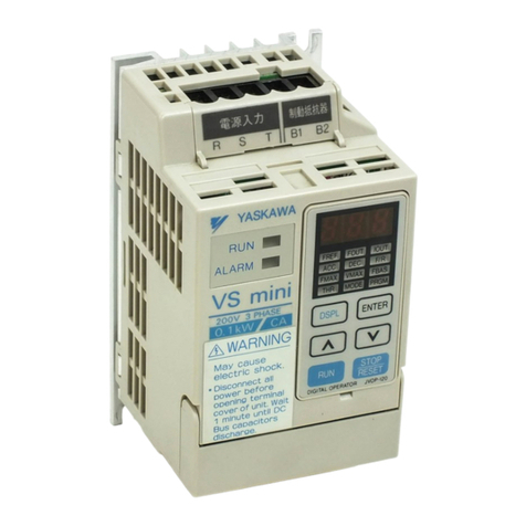
YASKAWA VS mini C Series User manual

YASKAWA

YASKAWA VS mini C Series User manual
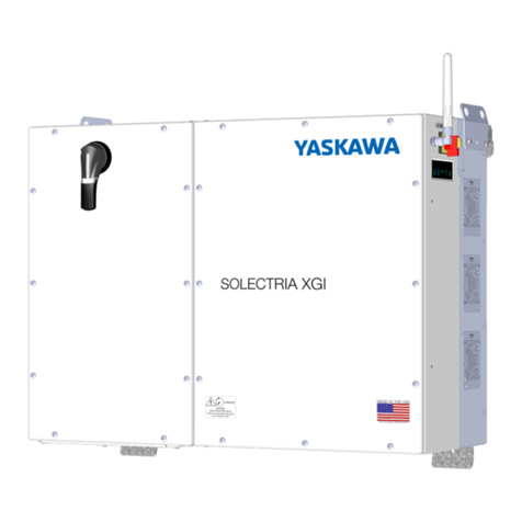
YASKAWA L7B User manual

YASKAWA

YASKAWA L7B User manual

YASKAWA Varispeed G7 Series User manual

YASKAWA

YASKAWA Varispeed G7 Series User manual

YASKAWA VS-606V7 Series User manual

YASKAWA

YASKAWA VS-606V7 Series User manual

YASKAWA SOLECTRIA XGI 1500 Series Operating instructions

YASKAWA

YASKAWA SOLECTRIA XGI 1500 Series Operating instructions

YASKAWA PVI 23 TL User manual

YASKAWA

YASKAWA PVI 23 TL User manual
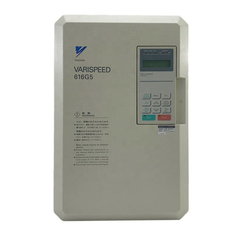
YASKAWA VS MINI J7 User manual

YASKAWA

YASKAWA VS MINI J7 User manual

YASKAWA VS mini C Series User manual

YASKAWA

YASKAWA VS mini C Series User manual

YASKAWA CIMR-MC5A20P4 User manual

YASKAWA

YASKAWA CIMR-MC5A20P4 User manual

YASKAWA VS-626M5 User manual

YASKAWA

YASKAWA VS-626M5 User manual

YASKAWA PVI 36TL User manual

YASKAWA

YASKAWA PVI 36TL User manual

YASKAWA Varispeed f7 Instruction manual

YASKAWA

YASKAWA Varispeed f7 Instruction manual

YASKAWA VARISPEED-616G5 User manual

YASKAWA

YASKAWA VARISPEED-616G5 User manual
YASKAWA FSDrive-MV1S User manual

YASKAWA

YASKAWA FSDrive-MV1S User manual
YASKAWA L1000A Series User manual

YASKAWA

YASKAWA L1000A Series User manual

YASKAWA Solectria PVI 25TL-208 Operating instructions

YASKAWA

YASKAWA Solectria PVI 25TL-208 Operating instructions

YASKAWA SOLECTRIA XGI 1500 Series Operating instructions

YASKAWA

YASKAWA SOLECTRIA XGI 1500 Series Operating instructions

YASKAWA A1000 Series Parts list manual

YASKAWA

YASKAWA A1000 Series Parts list manual

YASKAWA XGI 1000-65/65 Operating instructions

YASKAWA

YASKAWA XGI 1000-65/65 Operating instructions

YASKAWA CIMR-F7A User manual

YASKAWA

YASKAWA CIMR-F7A User manual

YASKAWA VS-616G5 Series Owner's manual

YASKAWA

YASKAWA VS-616G5 Series Owner's manual

YASKAWA Varispeed L7 User manual

YASKAWA

YASKAWA Varispeed L7 User manual
Popular Inverter manuals by other brands

Mitsubishi FR-F500 instruction manual

Mitsubishi

Mitsubishi FR-F500 instruction manual

mundoclima CL25620 Installation & owner's manual

mundoclima

mundoclima CL25620 Installation & owner's manual

Sima STP-150 User instructions

Sima

Sima STP-150 User instructions

FRO­NIUS Personal Display DL operating instructions

FRO­NIUS

FRO­NIUS Personal Display DL operating instructions

Power Tec 365S Operator's manual

Power Tec

Power Tec 365S Operator's manual

Sensata Dimensions 24NP36 owner's manual

Sensata

Sensata Dimensions 24NP36 owner's manual

MAKINEX GEN-7P Operator's manual

MAKINEX

MAKINEX GEN-7P Operator's manual

CyberPower CPS100BU user guide

CyberPower

CyberPower CPS100BU user guide

EnSmart SolarAll-H 1000T user manual

EnSmart

EnSmart SolarAll-H 1000T user manual

Morningstar TS-MPPT-60-600V-48-DB-TR Installation, operation and maintenance manual

Morningstar

Morningstar TS-MPPT-60-600V-48-DB-TR Installation, operation and maintenance manual

enphase IQ8MC Installation and operation manual

enphase

enphase IQ8MC Installation and operation manual

FRO­NIUS Datamanager 2.0 operating instructions

FRO­NIUS

FRO­NIUS Datamanager 2.0 operating instructions

DUROMAX Duro Star DS4400E user manual

DUROMAX

DUROMAX Duro Star DS4400E user manual

Juntek PSG9080 user manual

Juntek

Juntek PSG9080 user manual

Profi-Partner 46383 manual

Profi-Partner

Profi-Partner 46383 manual

Sungrow SH3.0RS user manual

Sungrow

Sungrow SH3.0RS user manual

Clenergy PV-ezRack Commercial Tilt installation guide

Clenergy

Clenergy PV-ezRack Commercial Tilt installation guide

Stanley PC509CA instruction manual

Stanley

Stanley PC509CA instruction manual

manuals.online logo
manuals.online logoBrands
  • About & Mission
  • Contact us
  • Privacy Policy
  • Terms and Conditions

Copyright 2025 Manuals.Online. All Rights Reserved.