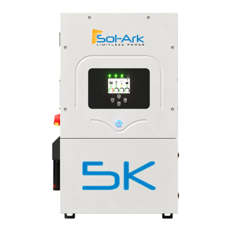
April 21, 2021 12
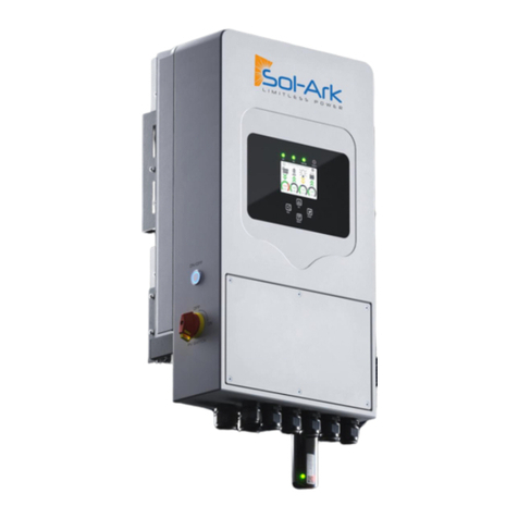
i. To connect batteries to the Sol-Ark 5K via RJ45, you will need to splice the end that connects to
the Sol-Ark 5K. Use the middle two conductors.
ii. RS485 is SunSpec draft 4 (will not work with draft 3)
d. Gen Start Signal (Two-Wire)
i. Normally open relay that closes when the Gen Start state is active
ii. If your generator only starts with the loss of 120/240V to the generator, we suggest using a
DPST relay to the output of the inverter.
e. PV Rapid Shutdown Signal
i. 12v signal/200mA power is present until the Sol-Ark is shut down with the front button
f. Emergency Stop Signal
i. Use a normally open switch to connect the two emergency stop pins, when triggered, the RSD
power supply will be cut and the inverter AC output will be stopped.
g. WI-FI Antenna
i. Needed for remote monitoring and/or software updates.
12. Testing and Powering up Sol-Ark 5K
a. Check Voltage of each PV input circuit
i. Should be no higher than 500Vdc open circuit temperature corrected.
ii. DO NOT connect PV+ OR PV- to GND.
iii. Good to verify polarity (if polarity is backwards the Sol-Ark will show a Voltage of 0V).
b. Check Grid Input Voltage (voltages shown are for North America)
i. Ensure 120Vac L1 to Neutral and L2 to Neutral.
ii. Ensure 240Vac L1 and L2.
iii. Check Neutral and Ground are ~0V AC.
c. Check Battery voltage
i. Turn on battery switch (if using a Lithium battery).
ii. Turn on the built-in battery disconnect in the user area of the Sol-Ark.
iii. Voltage should be 45Vdc-60Vdc.
d. If all checks out, Turn on Breakers for Grid and Load, Turn PV Disconnect knob to “On”
i. Note: (If PV is backwards: Sol-Ark will show a voltage of 0 for PV)
e. System will boot up with power from PV, Grid, or ON/Off Batt.
f. Press the ON/OFF Button on the front, light should come on.
g. If you installed limit sensors for Limited To Home selling mode, it is critical you verify the proper sensor
placement and direction. (Auto learn function avoids this section if not 208V or a no battery install,
function can be found under the advanced tab of the basic setup menu in settings).
i. Using AC multi-meter, verify L1 voltage on AC in/out is 0Vac with main L1 connection in panel.
Same for L2.
ii. To verify sensor connections to Sol-Ark, try removing one sensor from the main L1 connection.
The power should drop to 0W.
iii. To verify proper sensor direction, with any loads in the home, the HM: +watts will be positive. If
you turn on solar panels and turn enable Grid Sell, you should see HM: -watts if you are
producing more power than the loads are consuming. And if you turn on limited power to Home
mode, then HM: ~0 watts to zero the meter (system matches the loads to within 99%).
13. Basic Setup
a. Display: Auto dim must be enabled for LCD screen to be covered by warranty. Color LCD screens dim if
left on continuously for years.
b. Time: Set date and time for the system


