Refu sol 20K-2T User manual

Document No./Issue | 982079/05
Issue Date | 2021-03
Operating manual
Solar Inverter
REFUsol 20K-2T
REFUsol 33K-2T
Product | REFUsol 20K...33K-2T
Language | English
EnglishDeutsch

2
Copyright
© REFU Elektronik GmbH
The reproduction, distribution and utilization of this
document as well as the communication of its contents
to others without express authorization is prohibited.
Offenders will be held liable for the payment of dama-
ges. All rights reserved in the event of the grant of a
patent, utility model or design.
Liability
The data specified is only used to describe the product
and should not be interpreted as warranted characte-
ristics in the legal sense. The right to change the con-
tent of this documentation and the availability of the
products are reserved.
Publisher
REFU Elektronik GmbH
Marktstraße 185
72793 Pfullingen, GERMANY
✆ +49 7121 4332 0
✆ +49 7121 4332 333 (Service)
℻ +49 7121 4332 140
✉
✉
www.refu.com

3REFUsol 20K...33K-2T
982079 | 05 | 2021-03
EnglishDeutsch
Contents
1 About this Manual...................................... 5
1.1 Scope of this Manual .........................................5
1.2 Target Group of this Manual .............................5
1.3 Presentation of Information..............................5
1.3.1 Symbols ..................................................................... 5
1.3.2 Warnings in this Manual............................................ 6
2 Safety and Responsibility........................... 7
2.1 Safety Guidelines...............................................7
2.2 Rules for Safe Installation and Operation.........7
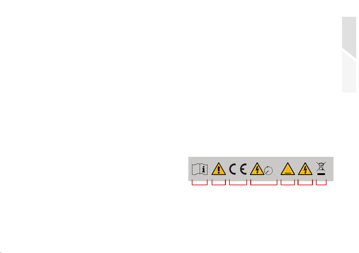
2.3 Symbols and Warnings on the Product.............7
2.4 Designated Use..................................................8
2.5 Improper Use.....................................................8
2.6 Requirements for Electricians..........................8
2.7 General Safety Instructions...............................8
2.8 Personal Protective Equipment ........................9
2.9 Five Safety Rules When Working on Electrical
Systems .............................................................9
3 Technical Description .............................. 10
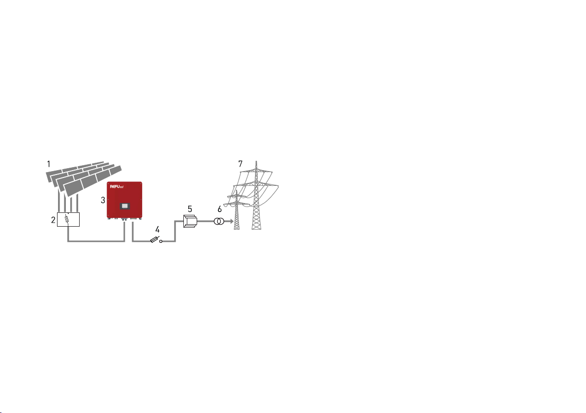
3.1 Functionality of the Inverter............................10
3.2 Cooling Concept ..............................................12
3.3 Connection Requirements.............................. 14
3.4 Compatible Grid Types ................................... 15
3.5 Components and Dimensions ........................ 16
3.6 Communication Interfaces............................. 19
3.7 Display and Operating Elements.................... 22
3.7.1 Keys ......................................................................... 23
3.7.2 Status-LEDs............................................................. 23
3.7.3 Information of the LCD display................................ 23
3.7.4 Menu Display ........................................................... 26
3.8 LED Display of the Ethernet and WiFi Stick ... 27
3.8.1 LED Display Ethernet Stick LSE-3 .......................... 28
3.8.2 LED Display WiFi Stick LSW-3 (optional) ................ 29
3.9 Efficiency and Power Diagrams ..................... 30
4 Installation ............................................... 31
4.1 Installation Warnings ..................................... 31
4.2 Auxiliary Means and Tools.............................. 31
4.3 Check Scope of Delivery ................................. 32
4.4 Requirements for the Installation Site........... 34
4.5 Mounting the Inverter Bracket ....................... 35
4.6 Remove the Inverter from the Packaging...... 36

4 REFUsol 20K...33K-2T
982079 | 05 | 2021-03
4.7 Mount Inverter.................................................36
4.8 Connect Earthing Conductor...........................37
4.9 Connect AC Cable............................................38
4.10 Assembling and Connecting DC Cables..........40
4.10.1 Assemble DC Cable................................................. 40
4.10.2 Connect DC Cable.................................................... 41
4.11 Connect Communication.................................41
4.11.1 Connect RS485 Communication.............................. 42
4.11.2 Connect Digital Inputs IN1 to IN4............................ 43
4.11.3 Connecting the Ethernet Stick LSE-3 ..................... 43
4.11.4 Connect WiFi Stick LSW-3 (optional) ...................... 44
4.11.5 REFUlog Monitoring Portal ..................................... 45
5 Commissioning ........................................ 46
5.1 Testing the Electrical Safety ...........................46
5.2 Commissioning the Inverter............................46
6 Operation ................................................. 46
6.1 Operation, Navigation and Key Functions.......46
6.2 Main Menu (v2.6)..............................................47
6.2.1 Main Menu > 1. Enter Setting.................................. 47
6.2.2 Main Menu > 2. Event List ....................................... 51
6.2.3 Main Menu > 3. System Info .................................... 51
6.2.4 Main Menu > 4. System Time .................................. 51
6.2.5 Main Menu > 5. Software (firmware) Update .......... 52
7 Error Messages and Troubleshooting..... 53
7.1 Maintenance ................................................... 67
7.1.1 General Warnings.................................................... 67
7.1.2 Maintenance Intervals............................................. 67
8 Decommissioning .................................... 68
8.1 Taking the Inverter Out of Operation.............. 68
8.2 Packing the Inverter ....................................... 68
8.3 Store Inverter.................................................. 68
8.4 Dispose Inverter ............................................. 69
9 Technical Data.......................................... 69
9.1 DC Data ........................................................... 69
9.2 AC Data ........................................................... 69
9.3 Performance................................................... 70
9.4 Protection ....................................................... 70
9.5 Communication............................................... 71
9.6 General Data................................................... 71

About this Manual 5
Scope of this Manual
REFUsol 20K...33K-2T
982079 | 05 | 2021-03
EnglishDeutsch
1 About this Manual
1.1 Scope of this Manual
This manual applies to the following products:
∘REFUsol 20K-2T Solar Inverter
∘REFUsol 33K-2T Solar Inverter
1.2 Target Group of this Manual
This manual is intended for installers, operators,
service technicians and plant operators.
This manual contains basic information, to assem-
ble the product safely and properly, to transport, to put
into operation and to operate.
▷Read this manual completely and in particular the
chapter "Safety and Responsibility", before you
work with the product.
1.3 Presentation of Information
To enable you to handle your product safely and
quickly with these instructions, uniform warnings,
symbols, designations and abbreviations are used.
1.3.1 Symbols
The following symbols indicate instructions which
are intended to make the instructions easier to under-
stand.
Tab. 1: Symbols/signs
Symbol Meaning
Useful information on the optimal and most eco-
nomical use of the product.
✅Prerequisite for an action that must be com-
pleted/executed beforehand.
▷Single action step that is to be executed.
▸Sub-step of an action step that is to be executed.
⟇Alternative action that can also be executed. Par-
tially conditioned by other prerequisites.
1.
2.
3.
Numbered action instruction that is to be exe-
cuted in the order listed.
➪Result of the action instruction.
... > ... Menu sequence in a software that is to be clicked
one after the other.

About this Manual6
Presentation of Information
REFUsol 20K...33K-2T
982079 | 05 | 2021-03
1.3.2 Warnings in this Manual
Warnings in this manual indicate an action where
there is a risk of personal injury or property damage.
Always observe the measures described to avert the
danger.
The warnings in this manual are presented in a box
that contains the following information:
SIGNAL WORD/WARNING CATEGORY
Type and source of danger
Consequences of ignoring the warnings.
▸Measures required to avoid the danger.
DANGER
Leads directly to death or serious personal injury if ig-
nored.
▸Follow the warnings to avoid death or serious injury!
WARNING
May result in death or serious personal injury if ignored.
▸Follow the warnings to avoid serious injuries!
CAUTION
May cause minor personal injury if ignored.
▸Follow the warnings to avoid injury!
NOTICE
Can lead to property damage if ignored.
▸Follow the warnings to avoid damage or destruction of
the product!

Safety and Responsibility 7
Safety Guidelines
REFUsol 20K...33K-2T
982079 | 05 | 2021-03
EnglishDeutsch
2 Safety and Responsibility
The product has been manufactured in accordance
with the generally accepted state of the art. Neverthe-
less, there is a risk of personal injury and property
damage if you do not observe this chapter and the
warnings in this manual.
▷Read this manual thoroughly and completely before
using the product.
2.1 Safety Guidelines
Installation, commissioning, and operation of the
product must be carried out by (electrically) qualified
personnel.
▷Read all technical information and safety instruc-
tions before installing and using the product.
2.2 Rules for Safe Installation and Operation
∘Do not attempt to install or operate the product
without proper training.
∘Ground the product properly.
∘Ground the metal supporting frame of the PV mod-
ules using potential equalization.
∘Only use PV modules of class A according to
IEC 61730 and of the same type.
∘Connect all cables properly.
∘Before switching on, check the AC and DC voltages
and polarity. Observe the information on the data
sheet or type plate.
∘Take appropriate precautions to protect against
electrostatic discharge (ESD).
∘Never remove the cover of the inverter.
∘To ensure safe operation, carry out all work profes-
sionally, including transport, storage, assembly, in-
stallation and operation.
2.3 Symbols and Warnings on the Product
Fig. 1: Symbols on the product
5 min
1 2 3 764 5

Safety and Responsibility8
Designated Use
REFUsol 20K...33K-2T
982079 | 05 | 2021-03
2.4 Designated Use
The REFUsol 20K...33K-2T, is a solar inverter, which
transforms the direct current generated by the PV gen-
erator (photovoltaic modules) into alternating current
and can feed it into mains supply.
The REFUsol 20K...33K-2T complies with protection
class IP65 and can be used indoors and outdoors.
2.5 Improper Use
Only the use described in the "Designated Use" is
permissible.
2.6 Requirements for Electricians
The activities described in this manual require basic
knowledge of the electrical system, the associated
technical terms and the relevant technical rules. To
ensure safe use, these activities may therefore only be
carried out by an appropriate specialist or a trained
person under the supervision of a specialist.
A skilled person is a person who, on the basis of his
professional training, his knowledge and experience as
well as his knowledge of the relevant regulations, can
assess the work assigned to him, recognize possible
dangers and take suitable safety measures.
2.7 General Safety Instructions
▷Observe the valid regulations for accident preven-
tion and environmental protection.
▷Observe the safety regulations and regulations of
the country in which the product is used.
▷Only use products in technically perfect condition.
▷Observe all notes on the product.
1Follow the instructions before use
2General warning
3CE marking
4Discharge time 5 minutes
5Warning of hot surface
6Warning of electrical voltage
7Proper disposal of waste electrical and electronic equip-
ment

Safety and Responsibility 9
Personal Protective Equipment
REFUsol 20K...33K-2T
982079 | 05 | 2021-03
EnglishDeutsch
▷Persons installing, operating or maintaining prod-
ucts must not be under the influence of drugs or
medication.
▷Use only accessories and spare parts approved by
REFU Elektronik GmbH in order to exclude a per-
sonal hazard due to unsuitable spare parts.
▷Observe the technical data and the ambient condi-
tions specified in the operating instructions.
▷Observe safety notes and instructions in third-party
documentation.
▷Do not put the product into operation until it has
been determined that it complies with country-spe-
cific rules, regulations, safety regulations/certifi-
cates and application regulations.
2.8 Personal Protective Equipment
REFU Elektronik GmbH recommends to wear the
following personal protective equipment.
∘Safety shoes
∘Protective gloves
∘If required: transport aid
∘Safety goggles
✅Observe the instructions of the respective manufac-
turer.
✅All components of the personal protective equip-
ment must be intact.
2.9 Five Safety Rules When Working on Elec-
trical Systems
Disconnect electrical systems (lock and tag)
according to the five safety rules:
▷Unlock and disconnect completely.
▷Secure against re-connection.
▷Check that there is no voltage (DC and AC).
▷Carry out earthing and short-circuiting.
▷Provide protection against adjacent live parts.

Technical Description10
Functionality of the Inverter
REFUsol 20K...33K-2T
982079 | 05 | 2021-03
3 Technical Description
3.1 Functionality of the Inverter
The REFUsol 20K...33K-2T is a multi-string inverter
with two MPP trackers that converts the DC voltage
generated by the photovoltaic modules into AC voltage
and can feed the power into the low or medium voltage
grid.
Fig. 2: Functional principle of a grid-connected PV system
A DC switch is integrated at the DC input of the
inverter; this disconnects the inverter from the PV
modules. The PV inverter has two independent MPP
trackers on the input board. These can be operated in
parallel mode or in independent mode.
The input board provides extensive functions,
including insulation monitoring, DC voltage and cur-
rent monitoring and reverse polarity protection. EMC
filtering is also performed on this board to suppress
unwanted noise levels at the DC input.
The DC-DC boost converter controls the level of the
DC voltage, which is fed to the inverter board, where
the DC current is converted into AC current. On the out-
put board, EMC filtering of the AC current, fault current
1Photovoltaik (PV) modules
2Solar string combiner box
3Photovoltaic inverter
4AC protection (fuse switch disconnector or circuit breaker)
5Grid protection
6Isolation transformer is required for medium-voltage grid
7Low or medium-voltage AC grid

Technical Description 11
Functionality of the Inverter
REFUsol 20K...33K-2T
982079 | 05 | 2021-03
EnglishDeutsch
monitoring and disconnection from the AC mains are
carried out by redundant AC relays.
The control and regulation board centrally moni-
tors, regulates and controls all unit functions. For this
purpose, all sensor data are recorded, processed and
the operating status of the inverter is displayed (LCD).
This includes the current operating data, error mes-
sages and warnings (warning LED).
The communication board enables the connection
of different adapters (RS485, Ethernet, WiFi) and the
communication of the inverter with other IT devices
(PC, smartphone) and web portals.
Depending on the design of the PV system and the
wiring of the individual PV modules, the PV strings can
be connected to two MPP trackers and operated in
"parallel mode" or "independent mode".
Independent mode (default)
If different PV outputs are expected at the two MPPT
inputs due to shading or different orientation (azimuth
or tilt angle), independent mode should be used for the
purpose of PV yield optimisation.
Parallel mode
If all PV strings are connected in parallel via a "com-
biner box" or Y-cable, "Parallel mode" must be used.
Fig. 3: Examples for MPPT operating modes
1Parallel mode
(open area with the same
orientation)
2Independent mode
(roof surfaces with differ-
ent orientation)
IN1 IN2 IN1 IN2
N
EW
S
12

Technical Description12
Cooling Concept
REFUsol 20K...33K-2T
982079 | 05 | 2021-03
3.2 Cooling Concept
Fig. 4: Cooling of the inverter

Technical Description 13
Cooling Concept
REFUsol 20K...33K-2T
982079 | 05 | 2021-03
EnglishDeutsch
Fig. 5: Overview circuit diagram REFUsol 20K...33K-2T (for REFUsol 20K-2T: 2 x PV per MPPT input; for 33K-2T: 3 x PV/MPPT input)
IN1
L1
L2
L3
N
PE
IN2
MPPT1
MPPT2
RCD
ISO 1
ISO 2
DC input
DC switch
DC EMC filter
DC-DC booster
DC-AC inverter
AC grid relais
AC EMC filter
AC output
microSD
card
Ethernet/WiFi
(optional)
RS485
In/Out
Remote
control
Alarm
(optional)
Control board
Isolation
monitoring
AC residual current detection
Communication
Display and
control
panel

Technical Description14
Connection Requirements
REFUsol 20K...33K-2T
982079 | 05 | 2021-03
3.3 Connection Requirements
The following points are to be considered when
planning the infrastructure:
∘The REFUsol 20K...33K-2T can feed into the low-volt-
age grid and the medium-voltage grid.
∘The power supply line must be equipped with an ap-
propriate AC disconnecting device.
∘The REFUsol 20K...33K-2T is not equipped with inter-
nal potential isolation.
∘If connected with the medium-voltage-grid, it must
be operated with electrically isolating transform-
ers.
∘The transfomer must be selected according to the
specific site of use and the relevant regulations
must be taken into account: Hazardous substances
ordinance, ordinance on installations for handling
substances hazardous to water, chemicals prohibi-
tion ordinance, technical instructions for noise pro-
tection, and regional building regulations.
∘The REFUsol 20K...33K-2T has 2 independent MPP
trackers. All PV modules connected to the same
MPPT should be of the same type and have the same
orientation.
∘When planning the system, selecting operating
equipment, installation, commissioning and com-
Additional required
equipment
at low voltage
network
at medium
voltage net-
work
DC load break switch integrated1)
1) Local regulation might require an additional DC switch at a external DC
combiner box.
integrated1)
AC load break switch necessary necessary
Central grid protec-
tion device with sec-
tion switch
(VDE-AR-N 4105,
VDE-AR-N 4110)
necessary necessary
LV-/MV-Transformer not necessary necessary
Specification of medium voltage transformer
Mains transformer according to EN 50588-1
Switching group Dyn5 or Dyn11

Technical Description 15
Compatible Grid Types
REFUsol 20K...33K-2T
982079 | 05 | 2021-03
EnglishDeutsch
missioning testing, take into account and adhere to
the specified rated data from the technical data
sheet.
3.4 Compatible Grid Types
The REFUsol 20K...33K-2T are compatible with the
TN-S, TN-C, TN-C-S and TT grid types. When using the
TT mains, the voltage between the neutral conductor
and earth should be less than 30 V.
Fig. 6: Overview of the grid types
PEN
L1
L2
L3
N
PE
L1
L2
L3
PEN
TN-S TN-C
L1
L2
L3
NPE
L1
L2
L3
N
PE
T N-C -S T T
TransformerTransformer
REFUsol REFUsol
REFUsol REFUsol

Technical Description16
Components and Dimensions
REFUsol 20K...33K-2T
982079 | 05 | 2021-03
3.5 Components and Dimensions
Fig. 7: Connection area REFUsol 20K-2T
Fig. 8: Connection area REFUsol 33K-2T
1Pressure compensation
membrane
2DC switch
3PV connection area IN1
(MPPT1)
4Ethernet or WiFi interface
5RS485 and digital input cover
6AC cover
7Heat sink (20K-2T only)
8PV connection area IN2
(MPPT2)
9DC positive connection
10 DC minus connection
10 7
IN1 IN2
9
123456
8
1Pressure compensation
membrane
2DC switch
3PV connection area IN1
(MPPT1)
4Ethernet or WiFi interface
5RS485 and digital input cover
6AC cover
7Heat sink with fans
8PV connection area IN2
(MPPT2)
9DC positive connection
10 DC minus connection
ON
OFF
WiFi / GPRS
PE N L1 L2 L3
AC
~
2354
16
7
IN1 IN2
10 98

Technical Description 17
Components and Dimensions
REFUsol 20K...33K-2T
982079 | 05 | 2021-03
EnglishDeutsch
Fig. 9: Structure of the type code
Fig. 10: Dimensions front view
1Housing cover
2LED display with membrane keys and status LEDs
Rated output power
20K- 2T ... 33K-2T
Number of MPP trackers
REFUsol
Brand name
1
2
528 mm
666 mm

Technical Description18
Components and Dimensions
REFUsol 20K...33K-2T
982079 | 05 | 2021-03
Fig. 11: Dimensions side view Fig. 12: Dimensions rear view
1Heat sink
2Inverter bracket
245 mm
1
2
528 mm

Technical Description 19
Communication Interfaces
REFUsol 20K...33K-2T
982079 | 05 | 2021-03
EnglishDeutsch
Fig. 13: Dimensions of the inverter bracket
Fig. 14: Type plate of the inverter
3.6 Communication Interfaces
The REFUsol 20K...33K-2T have 3 communication
ports: two RS485 interfaces and one Ethernet/WiFi
interface.
30 mm
364 mm
195.5 mm
45 mm
18.9 mm
110 mm
160 mm
12 mm
459 mm
336 mm
135 mm 135 mm
348 mm
10 mm
14 mm
9 mm
5 min
Model No. REFUsol 20K-2T (850P020.200)
Max. DC input voltage
Operating input voltage range
1 000 V
230 – 960 V
24 A
30 A
3/N/PE: 230/400 V
32 A
50, 60 Hz
32 kVA
0.8 ind ... 0.8 cap
IP65
-25 ... +60 °C
Class I
Max. current per MPPT
Max. short current per MPPT
Nominal grid voltage
Max. output current
Nominal grid frequency
Max. AC power
Adjustable power factor range
Type of protection
Ambient temperature
Made in China
Protective class
REFU Elektronik GmbH | Marktstraße 185
72793 Pfullingen | Germany
www.refu.com
Solar Inverter

Technical Description20
Communication Interfaces
REFUsol 20K...33K-2T
982079 | 05 | 2021-03
Fig. 15:Communication interfaces
1Ethernet/WiFi interface
2RS485 interface(s)
3microSD card slot
12
Communication port
WIFI/GPRS
ON
OFF IN1 IN2
PE N
IN1 IN2 IN3 IN4 GND DRM0NC COM NO
AC
~
RS485 SD RELAYRS485
L1 L2 L3
WIFI/GPRS
IN1 IN2 IN3 IN4 GND DRM0NC COM NO
RS485 SD RELAYRS485
3
Tab. 2: Communication ports, digital inputs
Terminal connection
Designation IN1 IN2 IN3 IN4 GND DRM0
Function/circuit for power
reduction
IN1 ⇔ GND
PN= 0 %
IN2 ⇔ GND
PN= 30 %
IN3 ⇔ GND
PN= 60 %
IN4 ⇔ GND
PN= 100 %
Logic-GND –
Other manuals for 20K-2T
1
This manual suits for next models
1
Table of contents
Other Refu sol Inverter manuals
Popular Inverter manuals by other brands

FJC
FJC 53300 instruction manual

Voltech
Voltech ISC1500 Installation and operating instructions

Steca
Steca coolcept3 StecaGrid 3203 Installation and operating instructions

Steca
Steca Solarix PI 550 Installation and operating instructions

Sterling Power
Sterling Power Pro Power SB Pure Sine Wave manual

Sealey
Sealey PI700.V3 Instructions for use