YASKAWA Motoman WorldLite-50 User guide

Motoman, Incorporated
805 Liberty Lane
West Carrollton, OH 45449
TEL: (937) 847-6200
FAX: (937) 847-6277
24-Hour Service Hotline: (937) 847-3200
/QVQOCP:4%%QPVTQNNGT
#TE9QTNF.KVG
5[UVGO/CPWCN
HQT58:4QDQV
Part Number: 142719-1
Release Date: July 25, 2000
Document Version: 1
Document Status: Final

The information contained within this document is the proprietary property of Motoman, Inc., and may not be
copied, reproduced or transmitted to other parties without the expressed written authorization of Motoman,
Inc.
©2003 by MOTOMAN
All Rights Reserved
Because we are constantly improving our products, we reserve the right to change specifications without
notice. MOTOMAN is a registered trademark of YASKAWA Electric Manufacturing.

MOTO
MAN
i Arc-WorldLite 50 System Manual
TABLE OF CONTENTS
Section Page
LIST OF FIGURES...........................................................................................................................iii
LIST OF TABLES ............................................................................................................................iii
1 INTRODUCTION
1.1 About this Document ....................................................................................................1-1
1.2 System Overview .......................................................................................................... 1-2
1.2.1 System Layout ................................................................................................ 1-2
1.2.2 Major Components ......................................................................................... 1-2
1.2.3 Optional Equipment ........................................................................................ 1-2
1.3 Reference to Other Documentation................................................................................ 1-4
1.4 Customer Service Information ......................................................................................1-4
2 SAFETY
2.1 Introduction .................................................................................................................. 2-1
2.2 Standard Conventions .................................................................................................. 2-2
2.3 General Safeguarding Tips............................................................................................ 2-3
2.4 Mechanical Safety Devices ...........................................................................................2-3
2.5 Installation Safety ......................................................................................................... 2-4
2.6 Programming Safety ..................................................................................................... 2-4
2.7 Operation Safety ........................................................................................................... 2-5
2.8 Maintenance Safety....................................................................................................... 2-6
3 EQUIPMENT DESCRIPTION
3.1 SV3X Robot Description ...............................................................................................3-1
3.2 XRC Controller ............................................................................................................. 3-1
3.2.1 Playback Panel ............................................................................................... 3-2
3.2.2 Programming Pendant .................................................................................... 3-3
3.2.3 Brake Release ................................................................................................. 3-6
3.3 Operator Station............................................................................................................ 3-6
3.3.1 Cycle Start ...................................................................................................... 3-6
3.3.2 Emergency Stop (E-STOP) .............................................................................. 3-7
3.3.3 Door Status ..................................................................................................... 3-7
3.4 Stationary Weld Table................................................................................................... 3-7
3.4.1 Arc Shields ..................................................................................................... 3-7
3.5 Welding Equipment ...................................................................................................... 3-8
3.5.1 Power Sources ................................................................................................ 3-8
3.5.2 PWF Wire Feeder ............................................................................................3-9
3.5.3 Universal Welding Interface (UWI) .................................................................. 3-9
3.5.4 GMAW Torch .................................................................................................. 3-9
3.5.5 Motoman Torch Mount ................................................................................... 3-9

Arc-WorldLite 50 System Manual ii
MOTO
MAN
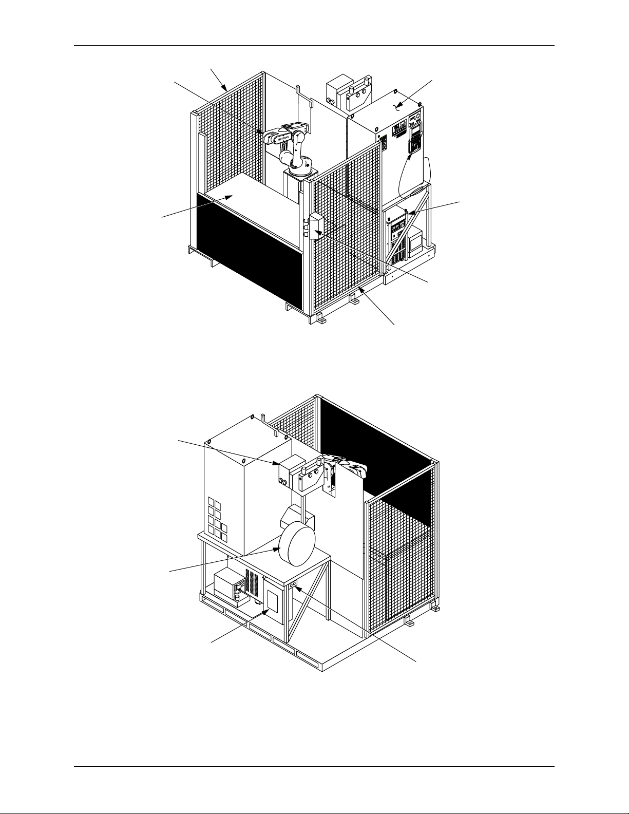
EQUIPMENT DESCRIPTION (CONTINUED)
3.6 Safety Features ............................................................................................................. 3-9
3.6.1 Arc Shields ................................................................................................... 3-10
3.6.2 Fencing ......................................................................................................... 3-10
3.6.3 Emergency Stops (E-STOPS) ........................................................................ 3-10
3.6.4 ENABLE Switch ............................................................................................. 3-10
3.6.5 Interlocked Cell Door .................................................................................... 3-10
3.6.6 Interference Cubes ........................................................................................ 3-11
3.6.7 Brake Release Control ................................................................................... 3-11
4 INSTALLATION
4.1 Materials Required........................................................................................................ 4-1
4.1.1 Customer-Supplied Items ............................................................................... 4-1
4.1.2 List of Tools Required ..................................................................................... 4-1
4.2 Site Preparation ............................................................................................................ 4-2
4.3 Installing the Arc-WorldLite 50 Common Base.............................................................4-2
4.3.1 Removing the Shipping Brackets .................................................................... 4-3
4.4 Leveling and Securing the Cell ..................................................................................... 4-4
4.5 Connecting the Cables.................................................................................................. 4-4
4.5.1 Connecting the Earth Ground .......................................................................... 4-4
4.5.2 Connecting the Water Circulator (Optional) .................................................... 4-5
4.6 Connecting the Gas/Air Services ..................................................................................4-6
4.7 Connecting the Power................................................................................................... 4-7
4.8 Conducting a Safety/Operation Check ..........................................................................4-7
4.9 Installation of Tooling and Fixtures............................................................................... 4-7
5 OPERATION
5.1 Programming................................................................................................................ 5-1
5.1.1 I/O Assignment ............................................................................................... 5-1
5.2 Daily Operation............................................................................................................. 5-2
5.2.1 Start-Up .......................................................................................................... 5-2
5.2.2 Robot Home Position ...................................................................................... 5-3
5.2.3 Starting the Master Job ................................................................................... 5-3
5.2.4 Shutdown ....................................................................................................... 5-3
5.3 System Recovery .......................................................................................................... 5-4
5.3.1 Alarms and Errors ........................................................................................... 5-4
5.3.2 E-STOP Recovery ........................................................................................... 5-4
5.3.3 Shock Sensor Recovery .................................................................................. 5-5
6 MAINTENANCE
6.1 Periodic Maintenance ................................................................................................... 6-1
6.2 Fuse and Circuit Breaker Protection.............................................................................. 6-2

MOTO
MAN
iii Arc-WorldLite 50 System Manual
LIST OF FIGURES
Figure Page
Figure 1-1 System Layout ............................................................................................................. 1-3
Figure 3-1 XRC Controller ............................................................................................................ 3-1
Figure 3-2 XRC Playback Panel .................................................................................................... 3-2
Figure 3-3 Programming Pendant ................................................................................................. 3-3
Figure 3-4 RS-232C Serial Port .................................................................................................... 3-5
Figure 3-5 Enable Switch ............................................................................................................... 3-5
Figure 3-6 Operator Station ...........................................................................................................3-6
Figure 3-7 Power Sources .............................................................................................................3-8
Figure 4-1 Area Needed for Installation .........................................................................................4-2
Figure 4-2 Unbolting the Arc-WorldLite 50 Common Base ........................................................... 4-3
Figure 4-3 Location of Shipping Brackets ..................................................................................... 4-3
Figure 4-4 Location of Leveling Bolts ........................................................................................... 4-4
Figure 4-5 Water Circulator Connections ...................................................................................... 4-6
Figure 4-6 Gas and Air Service Connections .................................................................................4-6
LIST OF TABLES
Table Page
Table 3-1 Positioner Specifications ............................................................................................ 3-7
Table 5-1 XRC User Inputs .......................................................................................................... 5-2
Table 5-2 XRC User Outputs ........................................................................................................5-2
Table 6-1 Periodic Maintenance .................................................................................................. 6-1
Table 6-2 Universal Welding Interface (UWI) Fuses .....................................................................6-2
Table 6-3 MotoArc 450 CV Fuses and Circuit Breaker.................................................................. 6-2

Arc-WorldLite 50 System Manual iv
MOTO
MAN
NOTES

MOTO
MAN
1-1 Arc-WorldLite 50 System Manual
SECTION 1
INTRODUCTION
The Arc-WorldLite 50 is part of the ArcWorld family of standardized arc welding
solutions. It is a fully integrated welding system, and is supported from wire to
weld by Motoman, Inc.
The Arc-WorldLite 50 features a Motoman SV3X arc welding robot and XRC
robot controller with menu-driven arc welding application software, complete
welding package, stationary weld table, and a total safety environment.
1.1 About this Document
This manual is intended as an introduction and overview for personnel who have
received operator training from Motoman, and who are familiar with the operation
of this Motoman robot model. For more detailed information, refer to the manuals
listed in Section 1.3. This manual contains the following sections:
SECTION 1 - INTRODUCTION
Provides general information about the Arc-WorldLite 50 and its components, a
list of reference documents, and customer service information.
SECTION 2 - SAFETY
Provides information regarding the safe use and operation of the Arc-WorldLite 50
system.
SECTION 3 - DESCRIPTION OF EQUIPMENT
Provides a detailed description of the major components of the Arc-WorldLite 50
system. This section also includes a table of component specifications.
SECTION 4 - INSTALLATION
Provides instructions for set up and installation of the Arc-WorldLite 50 system.
SECTION 5 - OPERATION
Provides instructions for basic operation of the Arc-WorldLite 50 system. This
section provides procedures for start-up, loading, normal operation, fault recovery,
and shutdown.
SECTION 6 - MAINTENANCE
Contains a table listing periodic maintenance requirements for the components of
the Arc-WorldLite 50 cell.

INTRODUCTION
Arc-WorldLite 50 System Manual 1-2
MOTO
MAN
1.2 System Overview
The Arc-WorldLite 50 provides a complete arc welding solution in a standardized
configuration. The system is designed around a Motoman SV3X arc welding robot
with XRC controller, and includes a complete welding package. A stationary weld
table with protective operator door provides easy operator access to parts, and a
safe welding environment. The cell provides a full complement of safety features
designed to protect both personnel and equipment. Figure 1-1 illustrates the system
layout of the Arc-WorldLite 50 cell.
1.2.1 System Layout
The robot manipulator, XRC controller and welding power source, all share a
common base for ease of installation and to help maintain proper alignment
between components. The Arc-WorldLite 50 cell is fully enclosed by sheet metal
and weld curtains to protect the operator. All operator controls are accessible from
outside the enclosure.
1.2.2 Major Components
The Arc-WorldLite 50 includes the following major components:
• Motoman SV3X manipulator and XRC controller
• Stationary weld table
• Operator station
• Welding equipment, including the following:
• Welding power source
• Torch (water-cooled or air-cooled)
• Wire feeder
• Torch mount
• Safety equipment, including the following:
• Protective arc screen
• Customer actuated Emergency Stops
• Software defined Interference Cubes
1.2.3 Optional Equipment
The following optional equipment is available for use with the Arc-WorldLite 50:
• Torch tender
• Wire cutter
• Com-Arc III seam tracking unit
• Water circulator

INTRODUCTION
MOTO
MAN
1-3 Arc-WorldLite 50 System Manual
Figure 1-1 System Layout
AV
POWER
ALARM
ON
OFF
CONTROL
POWER
AMMETERVOLTMETER
0
_
ON
OFF
ON
OFF
CO
2
MAG
FLOW
AUTO
SOLO
FON
Ø16
Ø14
Ø12
GASFLOWWIREDIA
WIRETYPE
GAS
PENETRATION
CRATER
ALARM
INDICATOR
CURRENT
INPUT
CABLE
HEAT
WATER FUSE
CRATERVOLTAGE
CRATERCURRENT
SERVO ON
READY
REMOTE
PLAY
(OFF)(ON)
TEACH
MODE EMERGENCY STOP
EDIT LOCK ALARM
HOLDSTART
YASNACXRCSK16X
ON
TRIP
O
P
E
N
/
R
O
F
F
WORLDLITE
by MOTOMAN
REAR VIEW
FRONT VIEW
XRC CONTROLLER
POWER SOURCE
SAFETY FENCE
ROBOT
CELL DOOR
POSITIONER
OPERATOR STATION
110 VOLT OUTLET
WIRE FEEDER
WIRE CASSETTE
POWER
DISCONNECT

INTRODUCTION
Arc-WorldLite 50 System Manual 1-4
MOTO
MAN
1.3 Reference to Other Documentation
For additional information refer to the following:
• Motoman SV3X Manipulator Manual (P/N 139067-1)
• Motoman Operator's Manual for Arc Welding (P/N 142098-1)
• Motoman Concurrent I/O Parameter Manual (P/N 142102-1)
• Com-Arc III Instruction Manual (P/N 132753-1)
• Vendor manuals for system components not manufactured by Motoman
1.4 Customer Service Information
If you are in need of technical assistance, contact the Motoman service staff at
(937) 847-3200. Please have the following information ready before you call:
• Robot Type (SV3X)
• Application Type (welding)
• System Type (Arc-WorldLite 50)
• Software Version (3.74)
• Robot Serial Number (located on the back side of the robot arm)
• Robot Sales Order Number (located on back side of XRC controller)

MOTO
MAN
2-1 Arc-WorldLite 50 System Manual
SECTION 2
SAFETY
2.1 Introduction
.
We suggest that you obtain and review a copy of the ANSI/RIA National Safety
Standard for Industrial Robots and Robot Systems. This information can be
obtained from the Robotic Industries Association by requesting ANSI/RIA
R15.06. The address is as follows:
Robotic Industries Association
900 Victors Way
P.O. Box 3724
Ann Arbor, Michigan 48106
TEL: 313/994-6088
FAX: 313/994-3338
Ultimately, the best safeguard is trained personnel. The user is responsible for
providing personnel who are adequately trained to operate, program, and maintain
the robot cell.
The robot must not be operated by personnel who have not been
trained!
We recommend that all personnel who intend to operate, program, repair, or use
the robot system be trained in an approved Motoman training course and become
familiar with the proper operation of the system.
This safety section addresses the following:
• Standard Conventions (Section 2.2)
• General Safeguarding Tips (Section 2.3)
• Mechanical Safety Devices (Section 2.4)
• Installation Safety (Section 2.5)
• Programming Safety (Section 2.6)
• Operation Safety (Section 2.7)
• Maintenance Safety (Section 2.8)
It is the purchaser's responsibility to ensure that all local, county,
state, and national codes, regulations, rules, or laws relating to
safety and safe operating conditions for each installation are met
and followed.

SAFETY
Arc-WorldLite 50 System Manual 2-2
MOTO
MAN
2.2 Standard Conventions
This manual includes information essential to the safety of personnel and
equipment. As you read through this manual, be alert to the four signal words:
• DANGER
• WARNING
• CAUTION
•NOTE
Pay particular attention to the information provided under these headings which
are defined below (in descending order of severity).
DANGER!
Information appearing under the DANGER caption concerns the
protection of personnel from the immediate and imminent hazards
that, if not avoided, will result in immediate, serious personal injury
or loss of life in addition to equipment damage.
WARNING!
Information appearing under the WARNING caption concerns the
protection of personnel and equipment from potential hazards that
can result in personal injury or loss of life in addition to equipment
damage.
CAUTION!
Information appearing under the CAUTION caption concerns the
protection of personnel and equipment, software, and data from
hazards that can result in minor personal injury or equipment
damage.
NOTE: Information appearing in a NOTE caption provides additional information which is helpful in
understanding the item being explained.

SAFETY
MOTO
MAN
2-3 Arc-WorldLite 50 System Manual
2.3 General Safeguarding Tips
All operators, programmers, plant and tooling engineers, maintenance personnel,
supervisors, and anyone working near the robot must become familiar with the
operation of this equipment. All personnel involved with the operation of the
equipment must understand potential dangers of operation. General safeguarding
tips are as follows:
• Improper operation can result in personal injury and/or damage to the
equipment. Only trained personnel familiar with the operation of this robot,
the operator's manuals, the system equipment, and options and accessories
should be permitted to operate this robot system.
• Do not enter the robot cell while it is in automatic operation. Programmers
must have the teach pendant when they enter the robot cell.
• Improper connections can damage the robot. All connections must be made
within the standard voltage and current ratings of the robot I/O (Inputs and
Outputs).
• The robot must be placed in Emergency Stop (E-STOP) mode whenever it is
not in use.
• In accordance with ANSI/RIA R15.06, section 6.13.4 and 6.13.5, use
lockout/tagout procedures during equipment maintenance. Refer also to
Section 1910.147 (29CFR, Part 1910), Occupational Safety and Health
Standards for General Industry (OSHA).
2.4 Mechanical Safety Devices
The safe operation of the robot, positioner, auxiliary equipment, and system is
ultimately the user's responsibility. The conditions under which the equipment will
be operated safely should be reviewed by the user. The user must be aware of the
various national codes, ANSI/RIA R15.06 safety standards, and other local codes
that may pertain to the installation and use of industrial equipment. Additional
safety measures for personnel and equipment may be required depending on
system installation, operation, and/or location. The following safety measures are
available:
• Safety fences and barriers
• Light curtains
• Door interlocks
• Safety mats
• Floor markings
• Warning lights
Check all safety equipment frequently for proper operation. Repair or replace any
non-functioning safety equipment immediately.

SAFETY
Arc-WorldLite 50 System Manual 2-4
MOTO
MAN
2.5 Installation Safety
Safe installation is essential for protection of people and equipment. The following
suggestions are intended to supplement, but not replace, existing federal, local, and
state laws and regulations. Additional safety measures for personnel and
equipment may be required depending on system installation, operation, and/or
location. Installation tips are as follows:
• Be sure that only qualified personnel familiar with national codes, local
codes, and ANSI/RIA R15.06 safety standards are permitted to install the
equipment.
• Identify the work envelope of each robot with floor markings, signs, and
barriers.
• Position all controllers outside the robot work envelope.
• Whenever possible, install safety fences to protect against unauthorized entry
into the work envelope.
• Eliminate areas where personnel might get trapped between a moving robot
and other equipment (pinch points).
• Provide sufficient room inside the workcell to permit safe teaching and
maintenance procedures.
2.6 Programming Safety
All operators, programmers, plant and tooling engineers, maintenance personnel,
supervisors, and anyone working near the robot must become familiar with the
operation of this equipment. All personnel involved with the operation of the
equipment must understand potential dangers of operation. Programming tips are
as follows:
• Any modifications to PART 1 of the controller PLC can cause severe
personal injury or death, as well as damage to the robot! Do not make any
modifications to PART 1. Making any changes without the written
permission of Motoman will
VOID YOUR WARRANTY!
• Some operations require standard passwords and some require special
passwords. Special passwords are for Motoman use only.
YOUR
WARRANTY WILL BE VOID
if you use these special passwords.
• Back up all programs and jobs onto a floppy disk whenever program changes
are made. To avoid loss of information, programs, or jobs, a backup must
always be made before any service procedures are done and before any
changes are made to options, accessories, or equipment.
• The concurrent I/O (Input and Output) function allows the customer to
modify the internal ladder inputs and outputs for maximum robot
performance. Great care must be taken when making these modifications.
Double-check all modifications under every mode of robot operation to
ensure that you have not created hazards or dangerous situations that may
damage the robot or other parts of the system.
• Improper operation can result in personal injury and/or damage to the
equipment. Only trained personnel familiar with the operation, manuals,
electrical design, and equipment interconnections of this robot should be
permitted to operate the system.

SAFETY
MOTO
MAN
2-5 Arc-WorldLite 50 System Manual
• Inspect the robot and work envelope to be sure no potentially hazardous
conditions exist. Be sure the area is clean and free of water, oil, debris, etc.
• Be sure that all safeguards are in place.
• Check the E-STOP button on the teach pendant for proper operation before
programming.
• Carry the teach pendant with you when you enter the workcell.
• Be sure that only the person holding the teach pendant enters the workcell.
• Test any new or modified program at low speed for at least one full cycle.
2.7 Operation Safety
All operators, programmers, plant and tooling engineers, maintenance personnel,
supervisors, and anyone working near the robot must become familiar with the
operation of this equipment. All personnel involved with the operation of the
equipment must understand potential dangers of operation. Operation tips are as
follows:
• Be sure that only trained personnel familiar with the operation of this robot,
the operator's manuals, the system equipment, and options and accessories
are permitted to operate this robot system.
• Check all safety equipment for proper operation. Repair or replace any non-
functioning safety equipment immediately.
• Inspect the robot and work envelope to ensure no potentially hazardous
conditions exist. Be sure the area is clean and free of water, oil, debris, etc.
• Ensure that all safeguards are in place.
• Improper operation can result in personal injury and/or damage to the
equipment. Only trained personnel familiar with the operation, manuals,
electrical design, and equipment interconnections of this robot should be
permitted to operate the system.
• Do not enter the robot cell while it is in automatic operation. Programmers
must have the teach pendant when they enter the cell.
• The robot must be placed in Emergency Stop (E-STOP) mode whenever it is
not in use.
• This equipment has multiple sources of electrical supply. Electrical
interconnections are made between the controller, external servo box, and
other equipment. Disconnect and lockout/tagout all electrical circuits before
making any modifications or connections.
• All modifications made to the controller will change the way the robot
operates and can cause severe personal injury or death, as well as damage the
robot. This includes controller parameters, ladder parts 1 and 2, and I/O
(Input and Output) modifications. Check and test all changes at slow speed.

SAFETY
Arc-WorldLite 50 System Manual 2-6
MOTO
MAN
2.8 Maintenance Safety
All operators, programmers, plant and tooling engineers, maintenance personnel,
supervisors, and anyone working near the robot must become familiar with the
operation of this equipment. All personnel involved with the operation of the
equipment must understand potential dangers of operation. Maintenance tips are as
follows:
• Do not perform any maintenance procedures before reading and
understanding the proper procedures in the appropriate manual.
• Check all safety equipment for proper operation. Repair or replace any non-
functioning safety equipment immediately.
• Improper operation can result in personal injury and/or damage to the
equipment. Only trained personnel familiar with the operation, manuals,
electrical design, and equipment interconnections of this robot should be
permitted to operate the system.
• Back up all your programs and jobs onto a floppy disk whenever program
changes are made. A backup must always be made before any servicing or
changes are made to options, accessories, or equipment to avoid loss of
information, programs, or jobs.
• Do not enter the robot cell while it is in automatic operation. Programmers
must have the teach pendant when they enter the cell.
• The robot must be placed in Emergency Stop (E-STOP) mode whenever it is
not in use.
• Be sure all safeguards are in place.
• Use proper replacement parts.
• This equipment has multiple sources of electrical supply. Electrical
interconnections are made between the controller, external servo box, and
other equipment. Disconnect and lockout/tagout all electrical circuits before
making any modifications or connections.
• All modifications made to the controller will change the way the robot
operates and can cause severe personal injury or death, as well as damage the
robot. This includes controller parameters, ladder parts 1 and 2, and I/O
(Input and Output) modifications. Check and test all changes at slow speed.
• Improper connections can damage the robot. All connections must be made
within the standard voltage and current ratings of the robot I/O (Inputs and
Outputs).

MOTO
MAN
3-1 Arc-WorldLite 50 System Manual
SECTION 3
EQUIPMENT DESCRIPTION
3.1 SV3X Robot Description
The Motoman SV3X robot and Xtra Robotic Controller (XRC) represent state-of-
the-art technology in robotics today. The six-axis SV3X robot has a payload of 3
kg (6.6 lbs). It features a 1,019 mm (40.1 in.) vertical reach and has a relative
positioning accuracy of ± 0.03 mm (0.001 in.).
The SV3X robot can reach below its own base as well as behind itself. The SV3X
can also be mounted in floor, wall, or ceiling configurations with few hardware
modifications. For more information, refer to the manipulator manual that came
with your system.
3.2 XRC Controller
The XRC robotic controller (see Figure 3-1) coordinates the operation of the Arc-
WorldLite 50 system. It controls manipulator movement and welding power
supply, processes input and output signals, and provides the signals to operate the
welding system. It maintains variable data and performs numeric processing to
convert to and from different coordinate systems. In addition, the controller
provides the following: main logic functions, servo control, program and constant
data memory, and power distribution. For more information, refer to the
manipulator manual that came with your system.
Figure 3-1 XRC Controller
SERVO ON
READY
REMOTE
PLAY
(OFF) (ON)
TEACH
MODE EMERGENCY STOP
EDIT LOCK ALARM
HOLD START
YASNAC XRC SV3X
ON
TRIP
O
P
E
N
/
R
E
S
E
T
O
F
F
PLAYBACK BOX
PROGRAMMING
PENDANT
BRAKE RELEASE
CONTROL
POWER
DISCONNECT

EQUIPMENT DESCRIPTION
Arc-WorldLite 50 System Manual 3-2
MOTO
MAN
3.2.1 Playback Panel
The playback panel (see Figure 3-2) contains the primary system controls and
consists of the features described below. For more information, refer to the
manipulator manual that came with your system.
Figure 3-2 XRC Playback Panel
Servo On Ready
The SERVO ON READY push button turns servo power ON. The switch lights
when servo power is on. In TEACH mode, the SERVO ON READY push button
operates only when the TEACH LOCK button on the programming pendant is ON
and the ENABLE switch on the programming pendant is held in.
Mode
The Mode push buttons (PLAY and TEACH) set the robot's mode of operation.
NOTE: Changing modes from PLAY to TEACH, during playback, will cause the program to cease
execution (similar to HOLD); to resume operation, press PLAY and then START.
Remote
This push button disables the playback panel and enables servo power to be
applied if play mode is set and positioner door is up.
Alarm/Error
The ALARM/ERROR indicator light turns ON whenever an alarm or error
condition occurs.
Emergency Stop (E-STOP)
The E-STOP button on the playback panel is connected in series with the system
Emergency Stop circuit. Pressing E-STOP ceases all system operation.
Start
Pressing the START button while in PLAY mode with servo power on, causes
playback execution of the current job to begin.
SERVO ON
READY
REMOTE
PLAY
(OFF) (ON)
TEACH
MODE EMERGENCY STOP
EDIT LOCK ALARM
HOLD START
MODE
BUTTONS
SERVO ON
READY
E-STOP
START
BUTTON
HOLD
BUTTON
REMOTE
MODE
ALARM/ERROR
INDICATOR
EDIT LOCK

EQUIPMENT DESCRIPTION
MOTO
MAN
3-3 Arc-WorldLite 50 System Manual
Hold
The HOLD button is a normally closed, momentarily actuated switch. Pressing
HOLD halts operation of the manipulator until another Start signal is sent.
3.2.2 Programming Pendant
The programming pendant (see Figure 3-3) is the primary user interface for the
system. The pendant has a 4x5-inch 12-line, 40-character LCD display and
keypad. The system uses the INFORM II robot language and a menu-driven
interface to simplify operator interaction with the robot. By using the pendant, the
operator can teach robot motion, and perform programming, editing, maintenance,
and diagnostic functions. The programming pendant consists of the items
described below. For more information, refer to the manipulator manual that came
with your system.
NOTE: The programming pendant LCD display goes dark after a few minutes of inactivity. Press any
key to restore screen.
Figure 3-3 Programming Pendant
General Purpose Display Area
The General Purpose Display Area displays the currently selected menu choice.
Menu Area
The Menu Area contains menu selections for the currently selected screen.
Emergency Stop (E-STOP)
The E-STOP button on the programming pendant is connected in series with the
system Emergency Stop circuit. Pressing the E-STOP button interrupts this circuit
and stops all system operation.
Keypad
The user keypad on the programming pendant serves as an input device. The keys
are grouped into different functional sections to simplify operator use.
GENERAL PURPOSE
DISPLAY AREA
STATUS AREA
MENU AREA
CURSOR
ENABLE
SWITCH
AXIS KEYS
ENTER KEY
NUMERIC KEYPAD
EMERGENCY
STOP BUTTON

EQUIPMENT DESCRIPTION
Arc-WorldLite 50 System Manual 3-4 MOTOMAN
Status Area
The Status Area shows system status via the following symbols:
•Active Robot, ExternalAxis, or Base Axis
R1, R2, R3; S1, S2, etc.; or B1, B2, etc.
•Coordinate System
Joint, World, Cylindrical, Tool, or User Frame
•Manual Speed Setting
Inching, Low, Medium, or High
•Cycle Mode
Step, 1-Cycle, or Auto
•System Status
E-Stop, Stop, Running/Start, Hold, or Alarm
•Additional Pages (when applicable)
TOP MENU Key
The TOP MENU key returns the pendant display to the initial start-up menu. The
cursor key can then be used to choose from the following menu icons:
•JOB
This icon accesses job selections including: Master Job, Select Job, Job
Capacity, and Create New Job while in TEACH mode.
•ARC WELDING, GENERAL, HANDLING, and SPOT WELDING
This icon allows you to select the applications available to the controller.
• VARIABLE
This icon accesses the display and editing menu for the arithmetic variables
and display of position variables.
• IN/OUT
This icon accesses DETAIL and SIMPLE displays of all XRC I/O signals. In
EDITING or MAINT. mode, Universal Outputs can be forced ON or OFF.
• ROBOT
This icon accesses robot information including: CURR.POS, POWER ON/
OFF, POS, COMMAND POS, SECOND HOME POS, OPE ORIGIN POS,
and TOOL and USER COORDINATE.
• SYSTEM INFO
This icon provides Version information for both hardware and software,
Alarm History, and Monitoring Time.
Area Key
The Area key moves the cursor to the different areas of the display screen.
Cursor Key
The Cursor key is an 8-way, directional key that moves the up, down, left or right
to highlight a desired item that can then be chosen using the SELECT key.
u
LM H
S
C A
S
R
H A
This manual suits for next models
1
Table of contents
Other YASKAWA Welding System manuals