YASKAWA YWE-EH500-6N0 User manual

YASKAWA
YASKAWA MANUAL NO.
HW0480311 2
MOTOWELD-EH500
INSTRUCTIONS
TYPE: YWE-EH500-6N0(INPUT VOLTAGE: 480V)
Upon receipt of the product and prior to initial operation, read these instructions thoroughly, and retain
for future reference.
1/129
180369-1CD
0

ii
HW0480311
HW0480311
• This instruction manual is intended to explain operating instructions
and maintenance procedures primarily for the MOTOWELD-EH500. Read
this manual carefully and understand the contents before handling the
MOTOWELD-EH500. For the wire feeder, the welding torch, and the gas
regulator, read each instruction manual carefully.
• General items related to safety are listed in the Safety Manual Section
1: Safety. To ensure correct and safe operation, carefully read the Setup
Manual before reading this manual.
• Some drawings in this manual are shown with the protective covers or
shields removed for clarity. Be sure all covers and shields are replaced
before operating this product.
• The drawings and photos in this manual are representative examples
and differences may exist between them and the delivered product.
• YASKAWA may modify this model without notice when necessary due to
product improvements, modifications, or changes in specifications. If
such modification is made, the manual number will also be revised.
• If your copy of the manual is damaged or lost, contact a YASKAWA rep-
resentative to order a new copy. The representatives are listed on the
back cover. Be sure to tell the representative the manual number listed
on the front cover.
• YASKAWA is not responsible for incidents arising from unauthorized
modification of its products. Unauthorized modification voids your prod-
uct’s warranty.
MANDATORY
CAUTION
2/129

iii
HW0480311
HW0480311
Notes for Safe Operation
Read this manual carefully before installation, operation, maintenance, or inspection of the
MOTOWELD-EH500.
In this manual, the Notes for Safe Operation are classified as “WARNING,” “CAUTION,”
“MANDATORY,” or “PROHIBITED.”
“Serious injury” described above indicates loss of eyesight, injuries, burns (both due to high/
low temperature), electric shock, fractures, poisoning, etc. which may cause personnel to suf-
fer aftereffects, hospitalization, or prolonged out-patient medical treatment.
“Moderate injury” indicates injuries, burns, or electric shock which does not require hospital-
ization or prolonged out-patient medical treatment.
“Damage to equipment” indicates expanded damages relating to property or equipment.
Even items described as “CAUTION” may result in a serious accident in some situations. At
any rate, be sure to follow these important items.
For safe training concerning welding, utilize technical institutes held by the welding society or
association, or related societies or associations, technical courses held by the headquarters
or their branches, or qualifications examinations for welding technicians or engineers.
Indicates a potentially hazardous situation which, if not
avoided, could result in death or serious injury to personnel.
Indicates a potentially hazardous situation which, if not
avoided, could result in minor or moderate injury to personnel
and damage to equipment. It may also be used to alert against
unsafe practices.
Always be sure to follow explicitly the items listed under this
heading.
Must never be performed.
To ensure safe and efficient operation at all times, be sure to follow all instructions, even if
not designated as “CAUTION” and “WARNING.”
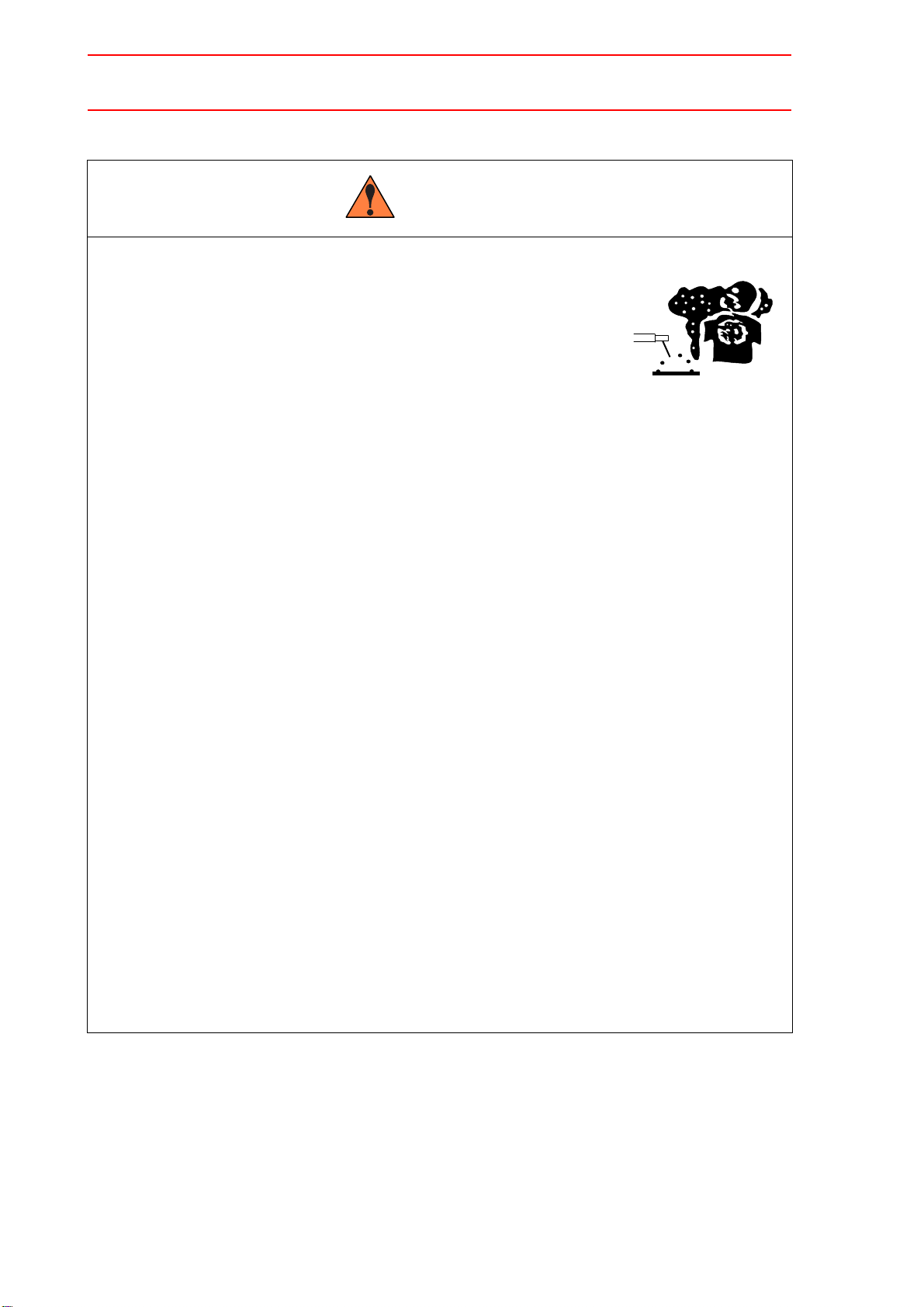
WARNING
CAUTION
MANDATORY
PROHIBITED
NOTE
3/129

iv
HW0480311
HW0480311
Be sure to observe the following warnings to avoid serious injury to personnel.
• Be sure to observe the precautions in this instruction manual although
this welder is designed and manufactured with sufficient consideration
given to safety.
Failure to observe this warning may result in death or serious injury to personnel.
• Observe the regulations and your own references for the construction of
the input power sources, selection of the installation site, handling of
high-pressure gases, storage and piping, storage of manufactured prod-
ucts after welding, disposal of wastes, etc.
• Do not let personnel to approach the welder or welding sites unneces-
sarily.
• Any person using a pacemaker must not approach the welder or welding
site under operation unless permitted by doctor.
The welder generates a magnetic field around it during current conduction, resulting in
bad influence on the pacemaker.
• Clean the cooling-water path once a month when using a water-cooled
torch and the cooling water circulator.
Failure to observe this warning may result in explosion or burns due to the choked path.
• In order to secure safe operations, only a trained or qualified person
who has understood the welder must perform installation, maintenance
and inspection, or repair of the welder.
• In order to secure safe operations, only a person that has understood
this instruction manual and has knowledge and techniques to handle
the welder safely must operate the welder.
• Do not use the welder for any applications other than welding.
WARNING
4/129

v
HW0480311
HW0480311
Be sure to observe the following warnings to avoid an electric shock.
• Never touch the charged parts.
Touching the charged parts may result in critical electric shock or burns.
• Only a qualified person in electric construction should perform ground-
ing construction for the welder case and base metals (to be welded) or
jigs that are electrically connected to the base metals as specified in
the electric facility technical reference.
• Be sure to perform installation or maintenance and inspection five min-
utes after all the input power supplies are turned OFF by using switches
in the switch box.
Even if the input power supply is turned OFF, the capacitor may still be charged. Be sure
to confirm that charged voltage is gone before starting operations.
• Do not use any cable of insufficient capacity or damaged or with its con-
ductor exposed.
• Tighten the cable connecting sections firmly and insulate them.
• Do not use the welder with its case or cover removed.
• Do not use worn, damaged or wet gloves. Always use dry insulated
gloves.
• Use lifelines when working at hights.
• Perform maintenance and inspection periodically. Repair damaged
parts immediately.
• Turn OFF all equipment input power supplies when not being used.
• When performing AC arc welding in a small space or at hights, be sure
to use equipment to prevent critical electric shock as specified by labor
safety and sanitary regulations.
WARNING
5/129

vi
HW0480311
HW0480311
Be sure to observe the following warnings and use protectors to protect
yourself or other people from the fumes or gases generated at welding and
short of the oxygen.
• In order to prevent gas poisoning or suffocation, be
sure to ventilate sufficiently or use an inhaler, etc.
when welding at a place specified by regulations such
as labor safety and sanitary regulations or hypoxia
preventive regulations.
• In order to prevent dust trouble or gas poisoning due to the fumes or
gases, use a local air exhaust facility specified by regulations such as
labor safety and sanitary regulations or dust trouble preventive regula-
tions or use effective protectors for breathing.
Fumes or gases generated at welding may harm your health.
• When welding within such areas as a tank, a boiler, or a ship’s hold, be
sure to ventilate sufficiently or use an inhaler, etc. in order to prevent or
offset any actual or potential oxygen shortage.
Gas heavier than air such as carbon dioxide gas or argon gas stays at the bottom.
• When welding in a small space, be sure to ventilate the site sufficiently
or use an inhaler. At the same time, operations must be done under
trained supervisor.
Welding operations at a small space may result in short of the air, causing a person to be
suffocated.
• Do not perform welding near degreasing, cleaning, or spraying opera-
tions.
Failure to observe this warning may generate extremely noxious gases.
• Before welding coated steel plates, be sure to ventilate sufficiently or
use protectors for breathing.
Welding such coated steel plates generates noxious fumes or gases.
WARNING
6/129

vii
HW0480311
HW0480311
Observe the following cautions to prevent fire, explosion, or rupture.
• Remove inflammables so that they will not get spattered.
If they cannot be removed, use the inflammables with
nonflammable covers.
Spatters or hot base metal immediately after welding may result in fire.
• Do not weld near flammable gases.
If arc is generated in a container (for inflammables) in which gasoline or the like is put, the
container may explode.
• Do not make hot base metals immediately after welding close to inflam-
mables.
• Remove inflammables at the hidden side when welding ceiling, floor, or
wall.
Failure to observe this caution may result in fire.
• Tighten and insulate the cable connections.
Imperfect cable connections or imperfect contacting section of the current path at the
base metal such as iron framework may result in fire due to heat generation by current
conduction.
• Connect the cable at the base metal as close to the welding part as pos-
sible.
• Do not weld a gas tube having gas inside or an enclosed tank or pipe.
Welding an enclosed tank or pipe may result in rupture.
• Locate fire extinguishers near the welding site.
WARNING
7/129

viii
HW0480311
HW0480311
Be sure to observe the following cautions and use protectors to protect yourself
or other people from arc beams, spatters, slugs or noise generated from weld-
ing.
• Wear welding mask or shaded glasses appropriate for
welding.
• Wear protective glasses to protect your eyes from spat-
ters or slags.
Scattered spatters or slags may damage eyes or burn the skin.
• Use such protectors as leather gloves, clothes with long sleeves, leg
covers, or leather aprons for welding.
• Install protective curtains around the welding site to protect your eyes
from arc beams.
Arc beams may irritate eyes or burn skins.
• Use noise protector when there is excessive noise.
Noise may damage hearing.
CAUTION
8/129

ix
HW0480311
HW0480311
Be sure to observe the following cautions to prevent a gas cylinder from fall-
ing or a gas regulator from rupturing.
• Observe the regulations and your own references for
the handling of gas cylinders.
Since a gas cylinder is filled with high pressure gas, improper handling may cause high
pressure gas to blow up, resulting in personal injury.
• Use the attached gas regulator or our recommended one.
• Read carefully the instruction manual of the gas regulator and observe
the precautions before using it.
• Hold the gas cylinder in the exclusive-use gas cylinder stand.
A gas cylinder falling may result in personal injury.
• Do not expose the gas cylinder to high temperature.
• Do not bring your face close to the discharging opening when opening
the valve of the gas cylinder.
• Be sure to attach the protective cap when the gas cylinder is not used.
• Do not hang the welding torch over the gas cylinder or keep the elec-
trode away from the gas cylinder.
Observe the following cautions to prevent personal injury due to improper handling.
• Do not use the welder with the case or cover removed.
• Only a qualified person or a person who has understood the
welder must remove the welder case for maintenance and
inspection or repair. Take preventive measures not to let
other personnel approach the welder or welding sites unnecessarily by
putting up a guard fence or the like.
• Do not contact the rotating cooling fan or feeding roll of the wire feeder
with hands, fingers, hair, or clothes.
Failure to observe this caution may cause someone to be caught in the machine resulting
in personal injury.
CAUTION
9/129

x
HW0480311
HW0480311
Observe the following cautions to prevent personal injury by the end tip of the weld-
ing wire.
• Do not peep through the chip hole to confirm that the wire
is being fed.
If the wire is projected from the end tip of the welding torch, it may poke
you in the eyes or face.
• Do not bring the welding torch end close to eyes, face, or body to per-
form inching or pulling the torch switch.
If the wire is projected from the end tip of the welding torch, it may poke you in the eyes,
face, or body.
• When hanging the wire feeder, remove the anti-fall fastening
from the spool shaft and tighten.
Failure to observe this caution may cause the wire to
be removed from the spool shaft, resulting in personal injury.
Observe the following cautions to prevent burns due to the plasma arc.
If body parts such as hands and fingers directly touch the plasma arc,
burns will result.
• Do not put your hands and fingers near the chip and
the electrodes of the torch end during cutting operation.
• Do not grasp near the base metal during cutting operation.
• Turn OFF the power supply before replacing the chip or the electrodes
of the torch.
CAUTION
10/129

xi
HW0480311
HW0480311
Observe the following cautions to prevent a fire accident caused by deterioration of
welder insulation.
• Perform all welding and grinding away from welder to pro-
tect welder from spattering and metal powder.
Spatter and metal powder inside the welder may cause a deterioration of
insulation resulting in accidental fire.
• Be sure to perform maintenance and inspection periodically to prevent
deterioration of insulation caused by accumulation of dust and dirt.
• If spatter or metal powder enters the inside of the welder, remove it by
forced air spray after turning OFF the welder and switch in the switch
box.
Spatter and metal powder inside the welder may cause a deterioration of insulation result-
ing in accidental fire.
CAUTION
11/129

xii
HW0480311
HW0480311
1Basic Specifications
2Installation and Connection
2.1 Installation Site and Welding Source Environment .2-1
2.2 Precautions on Grounding. . . . . . . . . . . . . . . . . . . . . . . . . .2-1
2.3 Power Supply Installed Capacity and Connection
Cables . . . . . . . . . . . . . . . . . . . . . . . . . . . . . . . . . . . . . . . . . . . . .2-2
2.4 Combination with Earth Leakage Breaker . . . . . . . . . .2-3
2.5 Connection of Electrical System. . . . . . . . . . . . . . . . . . . .2-3
2.6 Connection of Welding Voltage Detecting Line . . . . .2-7
2.7 Connection of Shielding Gas System. . . . . . . . . . . . . .2-10
2.7.1 For Mixed Gas or Carbon Dioxide Gas Welding. . . . . . . . . . . 2-10
2.7.2 Installation Site and Gas Cylinder Environment . . . . . . . . . . . 2-10
2.8 Ambient Environment . . . . . . . . . . . . . . . . . . . . . . . . . . . . .2-12
2.9 Precautions on Transporting . . . . . . . . . . . . . . . . . . . . . .2-13
3Welding Preparation
4Operations on Panel
4.1 Explanation of Welding Source Panel . . . . . . . . . . . . .4-1
4.2 Settings on Welding Source Panel . . . . . . . . . . . . . . . . .4-4
4.2.1 Changing Welding Type . . . . . . . . . . . . . . . . . . . . . . . . . . . . . . 4-4
4.2.2 User Files . . . . . . . . . . . . . . . . . . . . . . . . . . . . . . . . . . . . . . . . . 4-6
4.2.3 Changing P Parameters . . . . . . . . . . . . . . . . . . . . . . . . . . . . . . 4-6
4.2.4 Changing Common (C) Parameters. . . . . . . . . . . . . . . . . . . . . 4-7
4.2.5 Changing D Parameters. . . . . . . . . . . . . . . . . . . . . . . . . . . . . . 4-9
4.2.6 Saving Welding Conditions. . . . . . . . . . . . . . . . . . . . . . . . . . . 4-10
4.2.7 Checking the Flow Amount of Shielding Gas . . . . . . . . . . . . . 4-11
4.2.8 Selecting Feeding Motor. . . . . . . . . . . . . . . . . . . . . . . . . . . . . 4-11
4.2.9 Monitoring of Motor Current . . . . . . . . . . . . . . . . . . . . . . . . . . 4-12
4.2.10 System Reset. . . . . . . . . . . . . . . . . . . . . . . . . . . . . . . . . . . . 4-12
4.2.11 Lock Of Panel Operation . . . . . . . . . . . . . . . . . . . . . . . . . . . 4-14
4.3 List of Process Parameters. . . . . . . . . . . . . . . . . . . . . . . .4-16
4.4 List of Common Parameters. . . . . . . . . . . . . . . . . . . . . . .4-19
4.5 List of D Parameters . . . . . . . . . . . . . . . . . . . . . . . . . . . . . .4-21
12/129

xiii
HW0480311
HW0480311
5Welding Operation
5.1 Checking the Welding Conditions. . . . . . . . . . . . . . . . . . 5-1
5.2 Wire Stickout . . . . . . . . . . . . . . . . . . . . . . . . . . . . . . . . . . . . . . 5-1
5.3 Direction of Welding and Torch Angle. . . . . . . . . . . . . . 5-1
5.4 Precautions on Using Extension Cable . . . . . . . . . . . . 5-2
6Precautions on Welding
6.1 Error Detection Function. . . . . . . . . . . . . . . . . . . . . . . . . . . 6-1
6.2 Tripped Power Supply Switch. . . . . . . . . . . . . . . . . . . . . . 6-4
6.3 Precautions on Welding Operation. . . . . . . . . . . . . . . . . 6-4
7Built-in Functions
7.1 Internal Selecting Switches . . . . . . . . . . . . . . . . . . . . . . . . 7-1
7.2 Location of Printed Boards. . . . . . . . . . . . . . . . . . . . . . . . . 7-2
7.2.1 DIP Switch Settings for Pr(MB)-021 Board . . . . . . . . . . . . . . . .7-4
7.2.2 Jumper-pin Settings of the Pr(MB)-021 Board . . . . . . . . . . . . .7-4
8Maintenance and Inspection
8.1 Daily Inspection Items . . . . . . . . . . . . . . . . . . . . . . . . . . . . . 8-1
8.2 Bimonthly to Semiannual Inspection Items. . . . . . . . . 8-2
8.3 Annual Overhaul and Repair. . . . . . . . . . . . . . . . . . . . . . . 8-2
8.4 Guideline for Service Lifetime and Replacement of
Components Used. . . . . . . . . . . . . . . . . . . . . . . . . . . . . . . . . 8-3
8.5 Replace Fuse . . . . . . . . . . . . . . . . . . . . . . . . . . . . . . . . . . . . . 8-4
9Failure Analyses
9.1 Confirming Setting conditions. . . . . . . . . . . . . . . . . . . . . . 9-1
9.2 Cause and Remedy of Welding Section Failure. . . . 9-3
9.3 Cause and Remedy of Failure at Electrical Circuit
Section. . . . . . . . . . . . . . . . . . . . . . . . . . . . . . . . . . . . . . . . . . . . 9-6
13/129

xiv
HW0480311
HW0480311
10 Robot Interface Signals
10.1 Specifications of Robot Interface Signals. . . . . . . . .10-1
10.2 Meaning and Function of Pr(RC2)-001 Terminal .10-4
10.2.1 TB2 Terminal . . . . . . . . . . . . . . . . . . . . . . . . . . . . . . . . . . . . 10-4
10.2.2 TB3 Terminal . . . . . . . . . . . . . . . . . . . . . . . . . . . . . . . . . . . . 10-5
10.3 Meaning and Function of Signal for Starting Point
Detecting Function (Optional board Pr(OP)-003
[EH500]) . . . . . . . . . . . . . . . . . . . . . . . . . . . . . . . . . . . . . . . . . .10-6
11 Connection System Diagram
12 Diagnosis Function
12.1 Starting up Welding Source in Diagnosis Mode . .12-1
12.2 Confirmation of DIP Switch Set Status . . . . . . . . . . .12-3
12.3 Confirmation of Software Version . . . . . . . . . . . . . . . .12-4
12.4 Confirmation of the Number of Welding Source Errors
12-5
12.5 Clear of Error Record. . . . . . . . . . . . . . . . . . . . . . . . . . . .12-6
12.6 End of Diagnosis Mode . . . . . . . . . . . . . . . . . . . . . . . . . .12-6
13 Process Parameters
(Adjustment of Welding Characteristics)
13.1 Adjustable Welding Characteristics . . . . . . . . . . . . . .13-1
13.2 Adjustment of Arc Start Characteristics . . . . . . . . . .13-2
13.2.1 Adjustment of Start Pulse. . . . . . . . . . . . . . . . . . . . . . . . . . . 13-2
13.2.2 Adjustment of Hot Characteristics . . . . . . . . . . . . . . . . . . . . 13-3
13.3 Adjustment of Arc End Characteristics . . . . . . . . . . .13-4
13.4 Adjustment of Short-circuit Welding Characteristics. .
13-6
13.5 Adjustment of Pulse Welding Characteristics. . . . .13-7
13.5.1 Adjustment of MAG/MIG Pulse Welding Characteristics . . . 13-7
13.5.2 Adjustment of MIG Pulse Welding Characteristics. . . . . . . . 13-8
13.6 Adjustment of Other Pulse Welding Characteristics .
13-9
13.7 Adjustment of Current Output Characteristics . . .13-10
14/129

xv
HW0480311
HW0480311
14 Calibration for External Resistance
14.1 Outline of External Resistance Calibration. . . . . . . 14-1
14.2 Procedure of External Resistance Calibration . . . 14-2
14.2.1 Connecting the Cable for Resistance Measurement. . . . . . .14-2
14.2.2 Measuring the External Resistance Value . . . . . . . . . . . . . .14-4
14.2.3 Display of External Resistance Setting Parameter . . . . . . . .14-6
14.2.4 Setting the D Parameter for Calibration of External Resistance to
"Enabled". . . . . . . . . . . . . . . . . . . . . . . . . . . . . . . . . . . . . . . . .14-6
15 Calibration Function of Welding Current
15.1 Overview of the Welding Current Calibration Function
15-1
15.2 Procedure of Welding Current Calibration. . . . . . . 15-2
15.3 Parameters for Welding Current Calibration Function
15-6
16 Welding Source Condition File of the Robot
Controller
17 Setting of Arc Monitoring Function
18 Operation by External Remote Mode
18.1 Gas Check. . . . . . . . . . . . . . . . . . . . . . . . . . . . . . . . . . . . . . 18-1
18.2 Switch of User Files. . . . . . . . . . . . . . . . . . . . . . . . . . . . . 18-2
19 List of Service Parts
15/129

1-1
HW0480311
HW0480311
1Basic Specifications
Item Specifications
Model MOTOWELD-EH500
Type YWE-EH500-6N0
Number of Phases,
Rated Input Voltage Three-phase, 480 V ±10 %
Rated Frequency 50/60 Hz common
Rated Input 27.5kVA
24.3 kW
Welding Current Adjust-
ment Range 30 to 500 A (depends on the wire diameter)
Welding Voltage Adjust-
ment Range 12 to 45 V (depends on the wire diameter)
Rated Operational Ratio 100 % (for 10 minutes)
Welding Type CO2short-circuit welding, MAG/MIG short-circuit welding, pulse welding
Welding Object Material Iron, stainless steel, aluminium (Refer to the “Type” on the panel for
details.)
Feeding Motor Types of feeding motors can be selected among;
0: Print servomotor (default setting)
1: Minertia servomotor for servo torch
2: 4-roller servomotor (YWE-WF-340MELC)
Wire Feeding speed 1.5 to 18 m/min
Wire Feeding
Slow-down Speed CO2 short-circuit welding: Approx. 3 m/min
(adjustable range by panel operation: 1.5 to 6 m/min)
MAG/MIG short-circuit welding and pulse welding: Approx. 2 m/min
(adjustable range by panel operation: 1 to 4m/min)
Encoder cable 5 m (standard), 7m max.
(Optional: 25 m max with a cable extender)
Gas Running-in Time Approx. 20 seconds (Can be adjusted by panel operation: 60000 sec-
onds max.)
Gas Pre-flow Time Approx. 0.06 seconds (Can be adjusted by panel operation)
Gas After-flow Time Approx. 0.5 seconds (Can be adjusted by panel operation)
Wire-stick Prevention
Time Approx. 0.2 seconds (Can be adjusted by panel operation: 0.02 to 0.4
seconds)
16/129

1-2
HW0480311
HW0480311
VoltageforStartingPoint
Detecting Function
(Optional)
Peak value: 220 V ±20 % (full-wave rectification)
External Dimensions
[mm] 371 x 810 x 641 (width x depth x height)
(excluding the projections such as screws or eyebolts)
Mass Approx. 70kg
Welding Voltage Setting
Method Can be switched by "Auto Adjustment/Individual" (Synergic/Indepen-
dent) button on the welding source panel.
Arc Touch Start Function This function can be used by the parameters D2-2, D2-3, and D2-4.
User File Number of files: 3
"Panel" or "robot" can be switched by the parameter D1-11.
Adjustment of Voltage
and Current Waveform
Control
Can be changed by P parameters in the user file.
Interface for Robot Con-
troller Refer to " 10 Robot Interface Signals ".
Output Setting Analog
Input 0 to 14 V (The set voltage, current, and wire feeding speed are displayed
on the welding source panel.)
Error Output Outputs the arc failure signal to the robot side. (Error contents are indi-
cated on the welding source panel.)
Output for Arc
Monitoring Outputs the signal corresponding to current or voltage to the robot side.
The output terminal stand for analog indicator is also available.
Power Supply of the
Heater for the Gas
Regulator
None
Standard Accessory Fuse contained in glass tube of 5A (2 fuse)
Fuse contained in glass tube of 10 A (1 fuse) for Pr(SD)-006 board
Remarks Front panel: Written in English
Item Specifications
17/129

2.1 Installation Site and Welding Source Environment
2-1
HW0480311
HW0480311
2Installation and Connection
2.1 Installation Site and Welding Source Environment
The welding source can be used under the following environmental conditions:
• Dry, indoor and at least 30 cm from the wall or peripheral devices
• Free from direct sunlight, wind, and rain
• Ambient temperature of 0 to 40°C
• Altitude less than 1000 m
• Free from direct splash of welding spatter or metallic fine powder at grinding
2.2 Precautions on Grounding
1. Be sure to perform secure grounding work (ground resistance must be 100 Ωor less)
on the welding source so as not to charge its case or lead to unstable operation.
2. Connect a grounding cable of 14 mm2or thicker to the terminal marked "GROUND" or
"EARTH".
3. Be sure to ground the base metal (ground resistance must be 100 Ωor less) as well
when or any other non-conductive material is placed under the base metal.
• The welding source can be moved easily by using the caster. After
installation, use the stopper to fix the welding source before starting
operations.
For precautions on transporting, see
" 2.9 Precautions on Transporting ".
• Be sure to turn OFF the main switch of the switchboard before perform-
ing the grounding work.
• If the welding source is used with rated input voltage: 480 V(6N0), the
ground resistance must be 100 Ωor less. Grounding must be performed
by authorized or certified personnel.
CAUTION
CAUTION
18/129

2.3 Power Supply Installed Capacity and Connection Cables
2-2
HW0480311
HW0480311
4. If there is a pool or pond between the grounding of the power supply switchboard and
the welding source, the leak current is concentrated in the pool or pond. In such a
case, connect the grounding with a cable to escape the leak current through the cable.
2.3 Power Supply Installed Capacity and Connection
Cables
The following table " Table. 1 Power Supply Installed Capacity and Cables " shows the power
supply installed capacity and connection cables which are required for using the welding
source.
The rated input voltage for the welding source is three-phase, 480V(6N0). The welding
source supports a voltage compensation circuit so that the equipment can operate at a power
voltage within ±10 % fluctuations of the rated value. All the same, it is recommended to use a
power supply as stable as possible. If fluctuations in power supply voltage exceed ±10 %,
welding source conditions cannot be guaranteed and problems may occur.
Diameter of the input cable and the fuse capacity must be in compliance with the table " Table.
1 Power Supply Installed Capacity and Cables ". Install a non-fuse breaker (NFB) or a switch
with fuse for each welding source.
The non fuse breaker used should be the same capacity of the fuse indicated in " Table. 1
Power Supply Installed Capacity and Cables ", and the tripping time at 600 % of the rated cur-
rent should be one second or longer (General motor breakers satisfy these requirements). If
breaker capacity is insufficient or primary voltage is too high, the breaker will be tripped when
the welding source is turned ON.
Table. 1 Power Supply Installed Capacity and Cables
Installed Capacity 30 kVA
Fuse Rated Current 75 A
(rated voltage: 480 V(6N0))
Input Cable 14mm2~22mm2
Outside diameter of acceptable
Input Cable φ27.0~φ30.0mm *1
Exclusive-use base metal cable 60mm2or more (cable length:5m or less)
80mm2or more (cable length:5m or more) *2
Grounding Cable 14 mm2or more
19/129

2.4 Combination with Earth Leakage Breaker
2-3
HW0480311
HW0480311
2.4 Combination with Earth Leakage Breaker
When the welding source is used in a construction site, in a place with high humidity, or on an
iron plate, iron framework, or surface plate with high conductivity, a leakage breaker should be
installed according to the proper regulations or laws. In such a case, connect a leakage
breaker of current sensitivity 30 mA for each welding source. The welding source may mal-
function because of the inverter operations depending on the model or current sensitivity of
the leakage breaker. Therefore, select a proper one for inverter drives.
2.5 Connection of Electrical System
1. Connection on the Welding Source Side
See " Fig. 1 Connection Diagram of Welding Source at Rear Face " for proper connec-
tions.
1) Input cable
Please remove the top cover and connect the cable with the input terminal of
the partition board.
Connected bolt of the input voltage terminal is M8.
2) Ground cable
2. Connection on the Welding Side
See " Fig. 2 Connection Diagram of Welding Source at Front Face " for proper connec-
tions.
1) Welding cable
The welding cable connects between the welding torch and power output termi-
*1 The input cable is passed from the hole for wiring in the back of the power supply.
When the outside diameter of the cable exceeds φ30.0mm, match the plate to the
size of the input cable, process the hole, and use it.
*2 Be sure to use cables for welding. Also, use cables with sufficient thickness for pulse
welding or current of 250 A or more. Excessively small gauge cables may result in
poor welding and cause abnormal heating resuoting in burn or fire.
• Open the disconnect switch of the swtichgear before connecting wires
between welding machine and primary power supply.
Even one imperfect contact in the connections precludes proper welding. Be sure to
make perfect connection to the base metal by using jigs.
NOTE
CAUTION
20/129
This manual suits for next models
1
Table of contents
Other YASKAWA Welding System manuals