®Shanghai Yatai Instrument Ltd JC Series Electric Counter User Manual
Address: Marketing Department: 8F Rongxin Mansion, 1851 North Sichuan Road Shanghai China, Tel: 021-51053127; 51053128
Technical support and Factory: No. 128 Zhenyuan Rd, Baoshan City industrial Park, Shanghai China, Tel: 021-36160962, 36160096 (English)
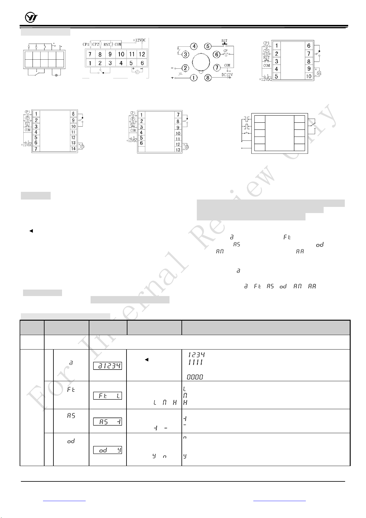
Wiring Terminals
CONTROL
OUTPUT CONTROL
OUTPUT
CP1CP2 RST COM
12VDC
1 2 3 4 5
6 7 8 9 10
CONTROL
OUTPUT POWER
SUPPLY
CONTROL
OUTPUT
POWER
SUPPLY OUTPUT
CONTROL
OUTPUT
POWER
SUPPLY
JC24S JC20S –FOR PANAL MOUNTING JC20S –FOR SOCKET MOUNITNG JC48S
The CP terminals for this model
are NPN type input unless specified
CONTROL
OUTPUT
POWER
SUPPLY
CONTROL
OUTPUT
POWER
SUPPLY
CP1
CP2
RST
COM
+12V
NC
OUT
NO
12VDC INPUT
CONTROL
OUTPUT
JC72S JC80S JC □ S- A Model - 12VDC INPUT
NOTE: JC □ S- A Model –12VDC wiring terminal is illustrated in the diagram, when external 12VDC power supply is connected from “+12V”
and “COM” terminals (different from other power supply types), the wiring should refer to the diagram shown in bottom right. When use other
types of power supply, they should be connected only from “power supply” terminal, and “+12V” terminal (internal 12VDC power output) is for
sensors only (no external power supply is allowed to connect to the “+12V” terminal, otherwise the counter might be damaged).
Instruction:
1. How to set the preset value:
In the counter mode: press the “preset/parameter” key for <3
seconds to enter the preset counter mode and the preset indicator
“SET” will be on. At this stage, the single digit will flush, then press
“ ”key to select the desired digit until it flashes, then press “▲”
key to choose any number from 0→9for the flashing digit. The
valid range for preset value is 0~999999 (note: the valid range for
JC48S is 0~99999). After the preset value is set and verified, press
the “preset/parameter” <3 seconds, the counter will automatically
exit the preset mode and enter the counting mode, and the preset
indicator will be off. The counter will remain in the existing settings
if the preset value is not modified. New parameters will be applied
immediately after the preset value is modified.
Note: For JC20S and JC24S, the "▲" key and the "clear" key are
identical,under the counting mode ,the key of“▲/clear” is used
to reset to zero,under the preset mode or parameter setting mode,
“▲/clear” is used to change the preset value or values of
parameters,it dose NOT function as clear key.
2.How to set the counting parameter:
JC series have six function parameters to choose including
software lock , counting frequency , increase/decrease
counting mode , power failure protection on/off , output
control , output time mono-stable delay . Press the
“preset/parameter”key more than 3s to enter the setting mode, the
parameter indicator “PA”will be on. The screen will display
software lock key . Press “preset/parameter”key for less than 3
seconds to choose the different function to modify according to
the following order:
Please refer to Table 2 for the more detailed instruction on how to
set and modify the function parameter.
T a b l e 2 : P a r a m e t e r s e t u p
Press “preset/parameter”key for more than 3 seconds to enter the setting mode, the indicator “PA”is on, enter the
following setting mode。
Step 2:
Press
“preset/pa
rameter”
key <
3s , select
and
modify
the
parameter
as
required
Press " " to select the
digits until it flahes, the
press "▲" to modify
: both the preset value and parameter value can be modified;
: only the preset value can be modified. Parameter value cannot
be modified except the software lock key;
: All value cannot be modified except the software lock key。
Press"▲",modify
single digit as
following:
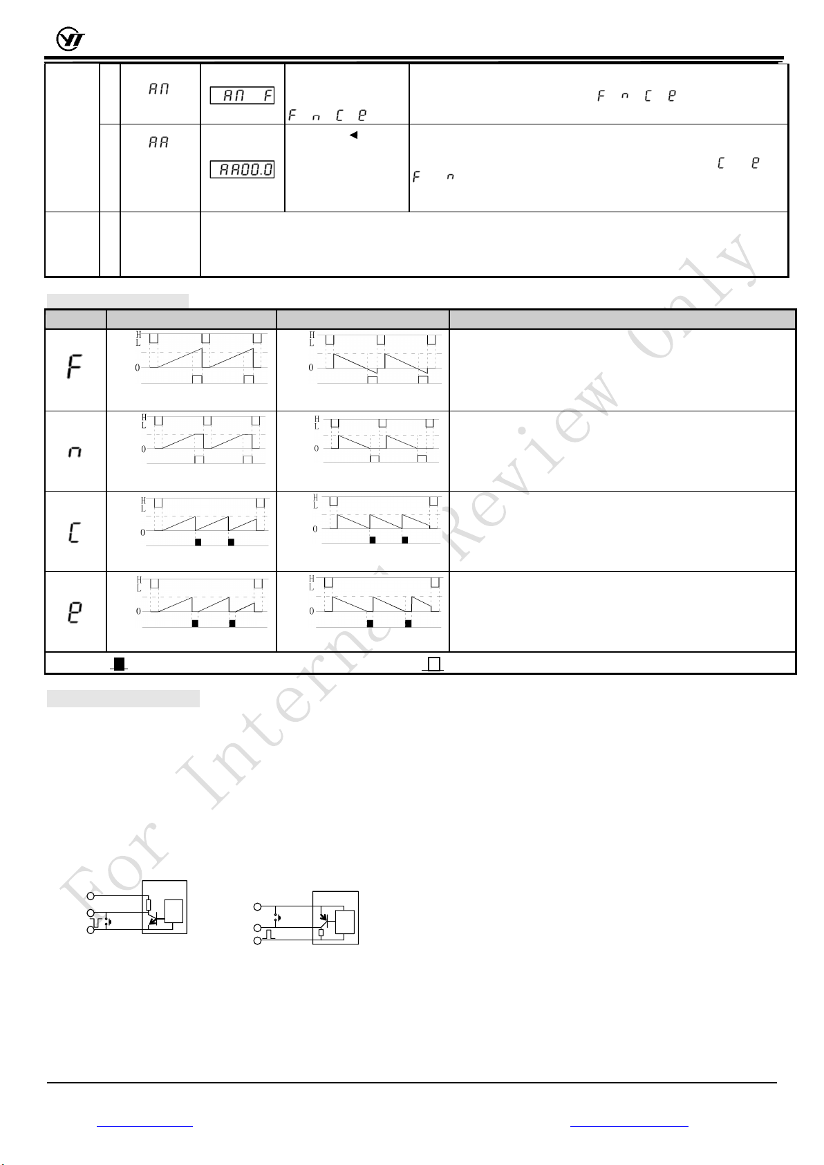
: maximum counting frequency is 23/second
: maximum counting frequency is 250/second
: maximum counting frequency is 5000/second
Press"▲",modify
single digit as
following:
power failure
protection
on/off
Press"▲",modify
single digit as
following :
:The counting value is not backup after the power failure, the counter
will start from 0 when the power is back on (the values of the presetting
and function are not changed)
:The counting value is backup for the power failure, the counter will
restart with the existing value when the power is back on.