Yellobrik P MV 1841 User manual

© 2011 - 2015 LYNX Technik AG all rights reserved
yellobrik
®
Reference Manual
P MV 1841
3G/HD/SD Quad Split Multiviewer
Revision 1.1 –March 2016
LYNXTechnik AG
Broadcast Television Equipment
This Manual Supports Device Revisions:
P MV 1841 Firmware Revision
728
®

P MV 1841 Reference Manual - Rev 1.1
Page 2 of 17
Table of Contents
Product Description .............................................................................................3
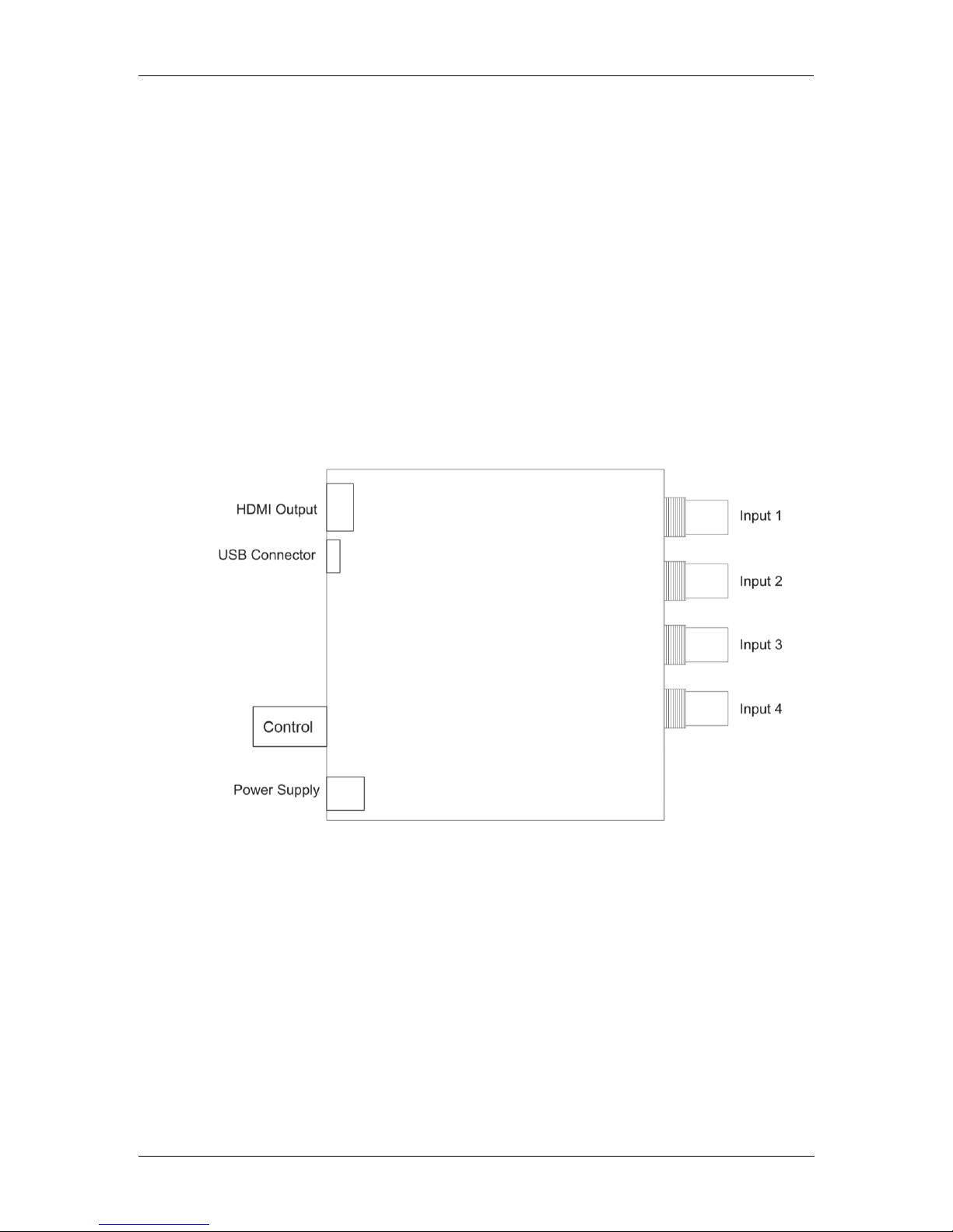
Controls and Connections....................................................................................3
On Screen Menu ...................................................................................................3
Multi............................................................................................................................................. 4
Video ........................................................................................................................................... 6
Text.............................................................................................................................................. 7
Audio ........................................................................................................................................... 8
Markers ....................................................................................................................................... 9
Scopes ...................................................................................................................................... 10
Alarms ....................................................................................................................................... 11
General...................................................................................................................................... 12
Exit............................................................................................................................................. 13
yelloGUI Compatible ..........................................................................................13
Warranty .............................................................................................................14
Regulatory information ......................................................................................15
Europe....................................................................................................................................... 15
Declaration of Conformity ..................................................................................................... 15
USA........................................................................................................................................... 15
FCC 47 Part 15..................................................................................................................... 15
Specifications ....................................................................................................16
Getting Help .......................................................................................................17
Support Contact.................................................................................................................... 17
LYNX Technik Knowledge Base........................................................................................... 17
General Product Info............................................................................................................. 17
Contact Information ...........................................................................................17

P MV 1841 Reference Manual - Rev 1.1
Page 3 of 17
Product Description
The P MV 1841 is a 3G/HD/SD-SDI Quad Split MultiViewer with an HDMI output. In addition to
the quad split functionality, the module can also accept a quad link 12G 4k.
The PMV 1841 is a compact quad split multiviewer ideal for applications needing basic quad split
multiview capability into an HDMI monitor. Four SDI inputs are supported with a single HDMI
output. The module has three basic modes of operation; Quad Split, Full Screen and 4K
Monitoring.
The module is simple to setup and configure using the integrated local control and on screen
menu system. All settings are automatically stored in flash RAM. USB is port is provided for
firmware updates and also PC/MAC control using the yelloGUI application.
Controls and Connections
On Screen Menu
To access the on screen menu press the control knob on the side of the module (press and hold
for 3 seconds if “lock” functionality is activated –see “General”for detailed description). Turn the
control knob to navigate through the menu. To enter a desired menu press the knob again.
To get back to the lower menu level, press the knob while the “back” entry is highlighted.
The on screen menu will automatically switch off after 5 seconds if not used or you can use the
Exit entry at the bottom of the root menu.

P MV 1841 Reference Manual - Rev 1.1
Page 4 of 17
Multi
The settings for the multiview display can be adjusted in this menu.
yellobrik –PMV1841 Quad Split
Multi
►
◄
Back
Video
Layout
Quad
Text
Output Resolution
1080p50
Audio
Border Color
White
Markers
Scopes
Alarms
General
Exit
- Layout
Sets the multiview layout and configuration.
oQuad
Classical quad split layout with all four input signals shown simultaneously.
oFull 1-4
Full image view of the selected input.
o4k UHD
Activating this mode will convert a quad link 12G 4k UHD (3840 x 2160) image to
a 3G output image.
o4k DCI
Activating this mode will convert a quad link 12G 4k UHD (4096 x 2160) image to
a 3G output image.
- Border Color
Choose the color for the multiview borders (Black / Gray [1, 2, 3, 4, 5, 6, 7, 8] / White /
Blue / Red / Magenta / Green / Cyan / Yellow).
- HDMI
oOutput Resolution
Sets the output resolution of the HDMI output.
1080p 60 / 50 / 30 / 25
1080i 60 / 50
720p 60 / 50
oBit Depth
Sets the bit depth of the HDMI output
Auto
8 Bit
10 Bit
12 Bit

P MV 1841 Reference Manual - Rev 1.1
Page 5 of 17
oColor Range
Sets the color range of the HDMI output
Auto
Limited
Full
oColor Space
Sets the color space of the HDMI output
Auto
RGB
YCbCr 4:2:2
YCbCr 4:4:4
oIT Content
Sets the IT content of the HDMI output
No Data
Graphics
Photo
Cinema
Game
oQuad Audio Src
Selects the audio source that is embedded into the HDMI output when in quad
view (in full view the audio of the selected input will automatically be embedded)
Input 1 –4
oTestpattern
The PMV1841 has an internal test pattern generator. Selecting a testpattern will
output this instead of the video input. The output standard is determined by the
HDMI Output Resolution setting.
100% Colorbar
75% Colorbar
Grey Scale
White
Green
Red
Blue
Black
Pludge
Cross Hatch
- Back
Select “back” to return to the root menu.

P MV 1841 Reference Manual - Rev 1.1
Page 6 of 17
Video
In this menu the individual input images can be configured.
yellobrik –PMV1841 Quad Split
Multi
◄
Back
Video
►
Select Input
1
Text
Display Video
ON
Audio
Size
000
Markers
H-Pos
000
Scopes
V-Pos
000
Alarms
Aspect Ratio
16:9
General
Exit
- Select Input
Choose the input (1 –4) which the following should affect.
- Display Video
Turn the selected input ON or OFF. When turned OFF, the video won’t be displayed even
if a valid signal is connected.
- Size
Adjusts the size (255 –150) of the image while maintaining the aspect ratio. The overlay
features will not be scaled. The fixed position overlays (e.g. IMD, video standards display,
time code, alarms etc.) will be moved outside of the image when scaling.
- H-Pos
Adjusts the horizontal position (0 –105) of the image. This parameter depends on the
size adjustment. If the image is full size, the H-Pos parameter does not have an effect. In
addition to this, the range of this parameter that has an effect depends on the amount
that the size has been reduced e.g. if the size has been reduced to 200 the range of the
H-Pos that has an influence on the image is from 0-55.
- V-Pos
Adjusts the vertical position (0 –105) of the image. The behavior and range of tis
parameter is the same as the H-Pos parameter.
- Aspect Ratio
Adjusts the aspect ratio (16:9 / 4:3) of the image.
- Back
Select “back” to return to the root menu.

P MV 1841 Reference Manual - Rev 1.1
Page 7 of 17
Text
Activate and adjust the text overlays.
yellobrik –PMV1841 Quad Split
Multi
◄
Back
Video
Video Standards
ON
Text
►
Show IMD
ON
Audio
Text Color
White
Markers
Select Input
1
Scopes
IMD
Camera 1
Alarms
Time Code
OFF
General
Exit
- Video Standards
Turn the video standard burn-in for all inputs ON or OFF.
- Show IMD
Turn the IMD (In Monitor Display) for all the inputs ON or OFF.
- Text Color
Choose the color of the text (Black / Gray [1, 2, 3, 4, 5, 6, 7, 8] / White / Blue / Red /
Magenta / Green / Cyan / Yellow). The text color for all the inputs will be affected.
- Select Input
Choose the input (1 –4) which the following should affect.
- IMD
Edit the xx character IMD text for the selected input. The IMD provides up to 16
characters.
- TimeCode
Turn the ATC time code burn-in ON or OFF for the selected input.
- Back
Select “back” to return to the root menu.

P MV 1841 Reference Manual - Rev 1.1
Page 8 of 17
Audio
This menu provides settings for the audio level meters for the individual inputs.
yellobrik –PMV1841 Quad Split
Multi
◄
Back
Video
Select Input
1
Text
Audio Meters
ON
Audio
►
No. of Channels
8
Markers
H-Pos
000
Scopes
V-Pos
000
Alarms
Meter Size
Small
General
Test Level
-18dBFS
Exit
PGM Level
-9dBFS
- Select Input
Choose the input (1 –4) which the following should affect.
- Audio Meters
Turn the audio level meters ON or OFF for the selected input.
- No. of Channels
Select the number of audio channels (4 / 8 / 16) for the audio level meter of the selected
input.
- H-Pos
Adjusts the horizontal position (0 –255) of the audio level meter.
- V-Pos
Adjusts the vertical position (0 –255) of the audio level meter.
- Meter Size
Choose between a small or large size of the audio level meter.
- Test Level
Adjust the threshold of the yellow test level indication (-60dBFS –0dBFS). This setting
affects the audio level meters of all the inputs.
- PGM Level
Adjust the threshold of the red peak program level indication (-60dBFS –0dBFS). This
setting affects the audio level meters of all the inputs.
- Back
Select “back” to return to the root menu.

P MV 1841 Reference Manual - Rev 1.1
Page 9 of 17
Markers
Activate and adjust the markers for the individual inputs.
yellobrik –PMV1841 Quad Split
Multi
◄
Back
Video
Select Input
1
Text
Center Cross
ON
Audio
Safe Area
85
Markers
►
Aspect Ratio
User
Scopes
Horizontal Markers
000
Alarms
Vertical Markers
000
General
Markers Color
White
Exit
Curtain Transparency
Med
- Select Input
Choose the input (1 –4) which the following should affect.
- Center Cross
Turn the center cross ON or OFF.
- Safe Area
Activate the safe area display. Choose between various safe area markers (80 / 85 / 88 /
90 / 93).
- Aspect Ratio
Choose between a long list of displayable aspect ratio markers (16:9 / 4:3 / 15:9 / 14:9 /
13:9 / 1.85:1 / 2.35:1 / 1.85:1 + 4:3 / User)
- Horizontal Markers
Adjusts the position (0 –255) of the horizontal user markers. Aspect Ratio needs to be
set to “User” for this adjustment to have an effect.
- Vertical Markers
Adjusts the position (0 –255) of the vertical user markers. Aspect Ratio needs to be set
to “User” for this adjustment to have an effect.
- Markers Color
Choose the color of the markers (Black / Gray [1, 2, 3, 4, 5, 6, 7, 8] / White / Blue / Red /
Magenta / Green / Cyan / Yellow). The markers color of all the inputs will be affected.
- Curtain Transparency
This control adjusts the transparency of the area outside of the markers (Full / Max / Med
/ Min). This adjustment of the curtain transparency will affect all inputs.
- Back
Select “back” to return to the root menu.

P MV 1841 Reference Manual - Rev 1.1
Page 10 of 17
Scopes
This menu provides settings for the waveform and vector scope displays for each input
individually.
yellobrik –PMV1841 Quad Split
Multi
◄
Back
Video
Select Input
1
Text
Waveform
ON
Audio
Type
RGB
Markers
H-Pos
000
Scopes
►
V-Pos
000
Alarms
Size
Small
General
Vectorscope
OFF
Exit
H-Pos
000
V-Pos
000
Size
Small
Transparency
OFF
- Select Input
Choose the input (1 –4) which the following should affect.
- Waveform
Turn the waveform display ON or OFF for the selected input.
- Type
Select the type of waveform (RGB / R / G / B / YCbCr / Y / Cb / Cr) that is to be
displayed.
- H-Pos
Adjusts the horizontal position (0 –255) of the waveform display.
- V-Pos
Adjusts the vertical position (0 –255) of the waveform display.
- Size
Choose between a small or large size of the waveform display.
- Vector
Turn the vector scope display ON or OFF for the selected input.
- H-Pos
Adjusts the horizontal position (0 –255) of the vector scope display.
- V-Pos
Adjusts the vertical position (0 –255) of the vector scope display.
- Size
Choose between a small or large size of the vector scope display.

P MV 1841 Reference Manual - Rev 1.1
Page 11 of 17
- Scope Transparency
Adjust the transparency (OFF / Min / Med / Max) of the scopes.
- Back
Select “back” to return to the root menu.
Alarms
This menu provides settings for alarm indications for each individual input.
yellobrik –PMV1841 Quad Split
Multi
◄
Back
Video
Select Input
1
Text
No Input
OFF
Audio
Black
OFF
Markers
No Audio
OFF
Scopes
Silence Audio Ch.
1
Alarms
►
No Input Color
Red
General
Black Color
Red
Exit
Black Duration
5s
Audio Color
Red
Silence Duration
5s
Silence Threshold
-30dBFS
- Select Input
Choose the input (1 –4) which the following should affect.
- No Input
Turn the “No Input” alarm indication ON or OFF for the selected input. This alarm
indicates a missing SDI input signal.
- Black
Turn the “Black” alarm indication ON or OFF for the selected input. This alarm indicates if
the content of the video is black.
- No Audio
Turn the “No Audio” alarm indication ON or OFF for the selected input. This alarm
indicates if no audio is embedded in the SDI input.
- Silence Audio Ch.
Activate the “Silence Audio Ch.” alarm indication for the selected input by selecting the
audio channel that is to be monitored (1 –16).
- No Input Color
Choose the color of the “No Input” alarm (White / Yellow / Cyan / Green / Magenta / Red /
Blue / Black). This setting will affect all inputs.

P MV 1841 Reference Manual - Rev 1.1
Page 12 of 17
- Black Color
Choose the color of the “Black” alarm (Black / Blue / Green / Red / Cyan / Magenta /
Yellow / White). This setting will affect all inputs.
- Black Duration
Setup the time (0s –60s) that the module should wait until it triggers the “Black” alarm.
This setting will affect all inputs.
- Audio Color
Choose the color of the Audio alarms (No Audio and Silence) (Black / Blue / Green / Red
/ Cyan / Magenta / Yellow / White). This setting will affect all inputs.
- Silence Duration
Setup the time (0s –60s) that the module should wait until it triggers the “Silence” alarm.
This setting will affect all inputs.
- Threshold
Define the audio level threshold (-60dBFS –0dBFS) for the “Silence” alarm. This setting
will affect all inputs.
- Back
Select “back” to return to the root menu.
General
This menu provides general settings and information for the device.
yellobrik –PMV1841 Quad Split
Multi
◄
Back
Video
OSD H-Pos
000
Text
OSD V-Pos
000
Audio
OSD Transparency
OFF
Markers
OSD Lock
ON
Scopes
Factory Reset
Alarms
Serial Number
999
General
►
SW Version
699
Exit
- OSD H-Pos
Adjusts the horizontal position (0 –255) of the on screen display.
- OSD V-Pos
Adjusts the vertical position (0 –255) of the on screen display.
- OSD Transp
Adjust the transparency (OFF / Min / Med / Max) of the on screen display.

P MV 1841 Reference Manual - Rev 1.1
Page 13 of 17
- OSD Lock
Activating this function will lock the OSD to avoid accidently turning the menu on by
knocking the control encoder. To indicate the activated “Lock” functionality the general
status LED of the module will be amber.
To access the “locked” menu press and hold the control encoder for 3 seconds.
- Factory Reset
Reset the module to the factory default configuration.
- Serial Number
Displays the serial number of the module.
- SW Version
This entry will display the software version that the module is running on. To update the
software, download the latest yelloGUI software from our homepage (www.lynx-
technik.com) and connect the module via USB to the computer running the software (the
module needs to be powered in order to update).
- Back
Select “back” to return to the root menu.
Exit
Pressing this entry will turn the on screen menu off.
yellobrik –PMV1841 Quad Split
Multi
Video
Text
Audio
Markers
Scopes
Alarms
General
Exit
yelloGUI Compatible
The P MV 1841 can also be setup / controlled via USB using a PC or MAC with the yelloGUI
software application which can be downloaded from our website.
www.lynx-technik.com

P MV 1841 Reference Manual - Rev 1.1
Page 14 of 17
Warranty
LYNX Technik AG warrants that the product will be free from defects in materials and
workmanship for a period of two (3) years from the date of shipment. If this product
proves defective during the warranty period, LYNX Technik AG at its option will either
repair the defective product without charge for parts and labor, or will provide a
replacement in exchange for the defective product.
In order to obtain service under this warranty, customer must notify LYNX Technik of the
defect before expiration of the warranty period and make suitable arrangements for the
performance of service. Customer shall be responsible for packaging and shipping the
defective product to the service center designated by LYNX Technik, with shipping
charges prepaid. LYNX Technik shall pay for the return of the product to the customer if
the shipment is within the country which the LYNX Technik service center is located.
Customer shall be responsible for payment of all shipping charges, duties, taxes and any
other charges for products returned to any other locations.
This warranty shall not apply to any defect, failure, or damage caused by improper use or
improper or inadequate maintenance and care. LYNX Technik shall not be obligated to
furnish service under this warranty a) to repair damage resulting from attempts by
personnel other than LYNX Technik representatives to install, repair or service the
product; b) to repair damage resulting from improper use or connection to incompatible
equipment; c) to repair any damage or malfunction caused by the use of non LYNX
Technik supplies; or d) to service a product which has been modified or integrated with
other products when the effect of such modification or integration increases the time or
difficulty servicing the product.
THIS WARRANTY IS GIVEN BY LYNX TECHNIK WITH RESPECT TO THIS PRODUCT
IN LIEU OF ANY OTHER WARRANTIES, EXPRESS OR IMPLIED. LYNX TECHNIK
AND ITS VENDORS DISCLAIM ANY IMPLIED WARRANTIES OF MERCHANTABILITY
OR FITNESS FOR A PARTICULAR PURPOSE. LYNX TECHNIK`S RESPONISIBILITY
TO REPAIR AND REPLACE DEFECTIVE PRODUCTS IS THE SOLE AND EXCLUSIVE
REMEDY PROVIDED TO THE CUSTOMER FOR BREACH OF THIS WARRANTY.
LYNX TECHNIK AND ITS VENDORS WILL NOT BE LIABLE FOR ANY INDIRECT,
SPECIAL, INCIDENTIAL, OR CONSEQUENTIAL DAMAGES IRRESPECTIVE OF
WHETHER LYNX TECHNIK OR THE VENDOR HAS ADVANCE NOTICE OF THE
POSSIBILITY OF SUCH DAMAGES.

P MV 1841 Reference Manual - Rev 1.1
Page 15 of 17
Regulatory information
Europe
Declaration of Conformity
USA
FCC 47 Part 15
This device complies with part 15 of the FCC Rules. Operation is subject to the following
two conditions: (1) This device may not cause harmful interference, and (2) this device
must accept any interference received, including interference that may cause undesired
operation.
Note: This equipment has been tested and found to comply with the limits for a Class A
digital device, pursuant to the part 15 of the FCC Rules. These limits are designed to
provide reasonable protection against harmful interference when the equipment is
operated in a commercial environment. This equipment generates, uses, and can radiate
radio frequency energy and, if not installed and used in accordance with the instruction
manual, may cause harmful interference to radio communications. Operation of this
equipment in a residential area is likely to cause harmful interference in which case the
user will be required to correct the interference at their own expense.
We LYNX Technik AG
Brunnenweg 3
D-64331 Weiterstadt
Germany
Declare under our sole responsibility that the product
TYPE: P MV 1841
To which this declaration relates is in conformity with the following
standards (environments E1-E3):
EN 55103-1 /1996
EN 55103-2 /1996
EN 60950-1 /2006
Following the provisions of 89/336/EEC and 73/23/EEC directives.
Winfried Deckelmann
Weiterstadt, August 2015
Place and date of issue Legal Signature

P MV 1841 Reference Manual - Rev 1.1
Page 16 of 17
Specifications
SDI Video Input
Number of Inputs
4x SDI video on 75 Ohm BNC connector
Supported Standards
SMPTE ST 259M (SDTV)
SMPTE ST 292-1 (HDTV 1,5 Gb/s)
SMPTE 424 M (3Gb/s) supporting ST 425-1 Level A and Level B-DL
4k Quad Link Standards
UHD 3840 x 2160
DCI 4096 x 2160
Return Loss
> 15dB to 1.5GHz and > 10dB up to 3GHz
Cable Length
Automatic cable EQ (Belden 1694A cable)
340m @ 270Mbit/s, 150m @ 1.5Gbit/s, 120m @ 3Gbit/s
HDMI Video Ouputs
Number of Outputs
1x HDMI on Type A connector
HDMI Standard
1.4a
Embedded Audio
2 Channels of selected Input for full view
Local Control
Type of control
On Screen Menu
Control
Rotary Push Encoder
Processing
Input to Output Delay
1 Frame
USB
Connector
Standard USB port for yelloGUI interface and firmware updates
(Mini Type “B” plug)
Physical
Size
138mm x 90mm x 22mm (5.13” x 3.54” x 0.86”) including connectors
Weight
230g (8.11oz)
Power
Consumption
+12VDC @ 4.9W nominal
Power Input Range
supports 10 - 14VDC
Ambient
Temperature
5 –40°C (41 –104°F)
Humidity
90% Humidity (non condensing)

P MV 1841 Reference Manual - Rev 1.1
Page 17 of 17
Getting Help
Support Contact
If the module isn’t working as expected, or have questions please contact your local
distributor, authorized dealer or reseller for more details. Please do not return products to
LYNX without an RMA.
For FAQs and Technical support visit http://support.lynx-technik.com
LYNX Technik Knowledge Base
Frequently asked questions
General Product Info
General product information is available on http://www.lynx-technik.com
Contact Information
Please contact your local distributor; this is your local and fastest method for obtaining
support and sales information.
LYNX Technik can be contacted directly using the information below.
Address LYNX Technik AG
Brunnenweg 3
D-64331 Weiterstadt
Germany
Website www.lynx-technik.com
E-Mail info@lynx-technik.com
LYNX Technik manufactures a complete range of high quality modular products for
broadcast and Professional markets, please contact your local representative or visit our
web site for more product information.
LYNXTechnik AG
Broadcast Television Equipment
Table of contents
Other Yellobrik Cables And Connectors manuals