yellobrik
®
LYNXTechnik AG www.lynx-technik.com
We are constantly adding more yellobrik modules.
Please visit our website for the latest product updates.
www.lynx-technik.com
Operation
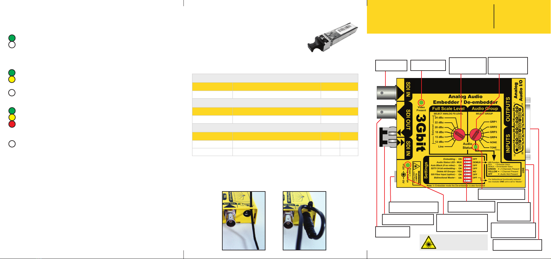
The PDM 1383 functions as a 4 channel embedder and de-embedder.
The module will also support simultaneous embedding and
deembedding where audio can be deembedded from the selected
audio group before overwriting it with new audio.
Rotary switches are provided for embedded audio group selection as
well as audio level, levels can be preset to an FS (full scale) level for
balanced audio, or line level for unbalanced audio.
(NOTE: An audio “group”is 2 x AES = 4 channels of audio)
Connections
All connections are clearly indicated on the
module. Analog audio I/O connections can
be made two ways, by directly wiring
connections to a suitable male 25 pin SubD
connector, or by using the supplied 25 pin
SubD PCB adapter with screw terminals.
25 pin SubD Adapter PCB with
screw terminals
Settings
A dip switch is provided for
module conguration.
Settings are indicated on the
module and self explanatory.
The “Auto Black” function will automatically output a black test signal on
the SDI output if the input video is lost. This allows for an uninterrupted
audio connection. Alternatively this mode can be used for analog audio
transport only.
Bidirectional Master
If a pair of modules are being used to transport audio (only) between
two locations then bidirectional functionality is possible when one of
the two modules is set to be the “Bidirectional Master” using the dip
switch. Please refer to the diagram.
PDM 1383 Set to
“Bidirectional Master”
PDM 1383, 1382
(or PDM 1284)
4 x Analog
Audio
4 x Analog
Audio
4 x Analog
Audio
4 x Analog
Audio
Fiber
(or copper SDI)
Only one end needs to be set as the Bidirectional Master, the other end
can be a PDM 1383, PDM 1382 or even a PDM 1284 for AES I/O
Cascading for More Audio Channels
All of our yellobrik Embedders/Deembedders can be cascaded to add
more audio channels. In the case of the PDM 1383 up to four modules
can be cascaded to support the full payload of 16 analog audio
channels. The conguration below shows two modules cascaded for 8
channels. (This example is using the “Auto Black” function and is for audio only - normal
SDI video could also be used)
Set to Group 1
Set to Group 1
Set to Group 2
Set to Group 2
4 x Analog
Audio
4 x Analog
Audio
4 x Analog
Audio
4 x Analog
Audio
Fiber
(or copper SDI)
SDI Input 1 x SDI - 75 Ohm BNC connector
SMPTE 424M, SMPTE 292M, SMPTE 259M
3G Level A & B-DL & B-DS according to SMPTE ST 425-1 and ST 425-2 (3D) with
image formats 1280 x 720 and 1920 x 1080
For a detailed list of supported formats please refer to the corresponding article
in our knowledge base (www.lynx-technik.com > support > tech.support)
Electrical Return Loss: >15dB from 5MHz to 1.5GHz, >10dB from 1.5GHz to 3GHz
Automatic cable EQ (Belden 1694A cable)
340m @ 270Mbit/s, 150m @ 1.5Gbit/s, 120m @ 3Gbit/s
Optical I/O
(Option)
1 x fiber optic input and output (see table)
SMPTE 297M - 2006
SDI Output 1 x SDI - 75 Ohm BNC connector
Output standard follows input
Audio Inputs 4 x analog audio inputs on 25 pin SubD Connector (10K Ohm)
Full scale analog audio level (or line level) selectable via rotar
AES group selection provided via rotary switch
Audio Outputs 4 x analog audio outputs on 25 pin SubD Connector (150 Ohm)
Full scale analog audio level (or line level) selectable via rotar
AES group selection provided via rotary switch
Power +12VDC @ 4.8W nominal - (supports 8 - 14VDC input range)
Multi-standard operation from 270Mbit/s to 3Gbit/s
SDTV (525/625)
720p and 1080p (23.98/24/25/29.97/30/50/59.94/60 Hz)
1080psf (23.98/24/25/29.97/30 Hz)
1080i (50/59.94/60 Hz)
NOTE: The module is designed for balanced audio signals. If using unbalanced audio
then the audio levels and full scale calibrations will not be accurate, there may also
be more noise on the signal.
Note: It is not possible
to cascade modules
when using the
“bidirectional” mode
Technical Specifications