YILMAZ REDÜKTÖR D Series User manual

YILMAZ REDÜKTÖR ISO 9001 YILMAZ REDÜKTÖR ISO 9001
D Series Gear Units
Operating Instructions
OIDEX0104/1114
o


3
Contents
1 How To Use This Manual .......................................................................................................... 05
2 Unit Designation........................................................................................................................ 06
2.1 Detailed unit designation ...................................................................................................... 06
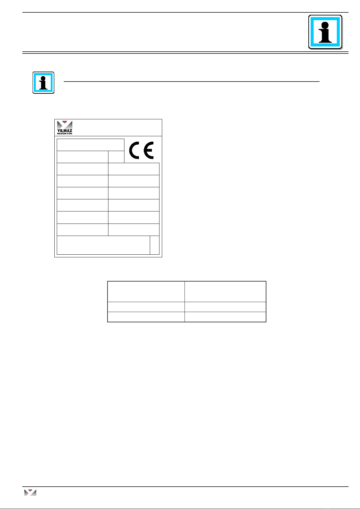
2.2 Nameplate unit designation.................................................................................................. 07
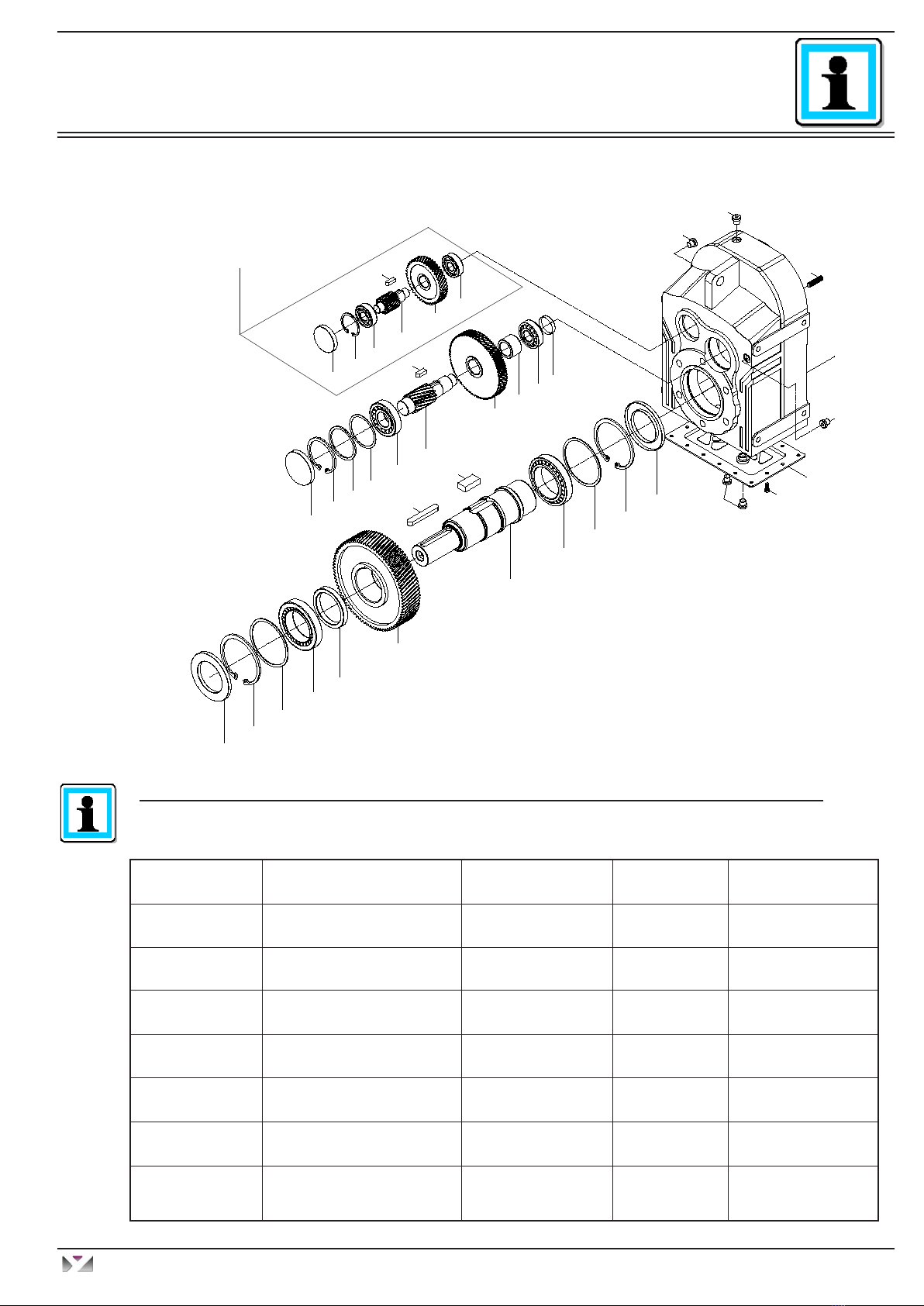
3 Part List of Standard Type Gear Units...................................................................................... 08
3.1 D...00... Type ................................................................................................................... 08
3.2 D...01... Type ................................................................................................................... 09
3.3 D...02... Type. .................................................................................................................. 10
3.4 D...03... Type ................................................................................................................... 11
3.5 D...0S...Type.................................................................................................................... 12
3.6 D...0E... Types................................................................................................................. 13
3.7 D..4 Additional Stage....................................................................................................... 14
3.8 D..5 and D..6 Additional Stages ...................................................................................... 15
3.9 D Series Motor Flange for Direct Coupled Types............................................................ 16
3.10 DN..., DV...Types B5, B14 Motor Flange....................................................................... 16
3.11 DT... Types Input Bearing Housing with Solid Input Shaft ............................................. 17
4- Things to Check Before the Gear Unit or Geared Motor is Installed....................... 18
4.1- Safety notes for use in potentially explosive atmosphere ................................. 18
4.2- Transportation ...................................................................................................19
4.3- Storage..............................................................................................................19
5- Installing the Gear Unit................................................................................................ 20
5.1- Before you start.................................................................................................20
5.2- Check Nameplate of the Gear Unit ................................................................... 20
5.3- Check the Ambient Conditions and Temperature.............................................. 20
5.4- Check Fitting Elements and the Shaft Dimensions to Fit .................................. 20
5.5- Check the Voltage Supply ................................................................................. 22
5.6- Check the Mounting Position ............................................................................ 22
5.7- Usage of Breather Plug..................................................................................... 22
5.8- Check the oil level ............................................................................................. 23
5.9- Check shaft ends and mounting faces .............................................................. 23
5.10- Cover abrasive ambient .................................................................................. 23
5.11- Check accessibility to filling, breather and drain plugs .................................... 23
6- Mechanical Installation................................................................................................ 24
6.1- Installing gear units in category II2G/D-II3G/D.................................................. 24
6.2- Installing Customer Shaft with Shoulder ........................................................... 25
6.3- Disassembling Customer Shaft with Shoulder .................................................. 26
6.4- Fitting Output Shaft Elements ........................................................................... 27
6.5- Correct Position of Output Shaft Elements ....................................................... 27
6.6- Fitting Couplings ............................................................................................... 28
6.7- Shaft Tightening Torques .................................................................................. 29
6.8- Assembling customer shaft with shrink disk..................................................... 30
6.9- Disassembling customer shaft with shrink disk................................................ 32
6.10- Assembling Gear Unit with Torque Arm ......................................................... 33
Operating Instructions
D Series
YILMAZ REDÜKTÖR
Contents

4
Operating Instructions
D Series
YILMAZ REDÜKTÖR
Contents
7 Maintenance & Inspection .................................................................................36
8 Lubrication..........................................................................................................37
8.1 Oil types............................................................................................................37
8.2 Changing the oil................................................................................................37
8.3 Mounting Positions ...........................................................................................38
8.4 Oil Quantities ...............................................................................................39-41
9 Troubleshooting Guide ......................................................................................43
10 Appendix ...........................................................................................................48
Warranty conditions................................................................................................48
Warranty.................................................................................................................49
Service Contact Points ...........................................................................................50

5
1 - How to Use This Manual
Take attention to the following safety and warning signs for proper understanding and quick reference.
Electrical Hazard; Can cause severe or fatal injuries.
Mechanical Hazard; Can cause severe or fatal injuries.
Likely to be Hazardous; Can cause minor or fatal injuries
Damage Risk; Can damage the gearbox or environment
Important Information
Important information about explosion protection
The operating instructions contain important information to ensure ;
- Trouble-free operation
- Fulfilment of any rights to claim under guarantee
The operating instruction must be kept close to the gearbox and must be available in case it is
needed.
This operating instruction is written for D series gear units and is applicable only for these series. If
any different type of gear unit is used please ask YILMAZ REDUKTOR. For special application and
modified gear units ask YILMAZ REDUKTOR for validity.
The D series gear units are with input shaft and without motor. The electric motor which will be con-
nected to the gear unit must also be in conformity with the ATEX (94/9/EC) standards.
All the external parts which will be assembled to the gear unit must conform ATEX (94/9/EC). The
product this declaration refers to must not be put into service until the machinery into which it is to be
incorporated has been declared in conformity with the provisions of the relevant European Directives.
If the gear unit is not operated as informed on this manual the gear unit is no longer ATEX conforming
and YILMAZ REDUKTOR does not take any responsibility.
o
Operating Instructions
D Series
YILMAZ REDÜKTÖR
General Informations
7 Maintenance & Inspection .................................................................................36
8 Lubrication..........................................................................................................37
8.1 Oil types............................................................................................................37
8.2 Changing the oil................................................................................................37
8.3 Mounting Positions ...........................................................................................38
8.4 Oil Quantities ...............................................................................................39-41
9 Troubleshooting Guide ......................................................................................43
10 Appendix ...........................................................................................................48
Warranty conditions................................................................................................48
Warranty.................................................................................................................49
Service Contact Points ...........................................................................................50

6
2 - Unit Designation
2.1- Detailed Unit Designation
Detailed D Series gear units designation for ordering
(This Designation is different from the short nameplate designation)
Motor Size
Gearbox Type
D Serie
Input Type
R : With Motor
N:IEC B5 / B14 Flanged without Motor
V:IEC B5 / B14 Flanged with Motor
T:With Input Shaft
Housing Size
1...9
Revision Number
Output Shaft
00:Hollow Shaft output
01:Solid Shaft Output
02:Solid shaft output with IEC B5 /14 Flange
03:Flanged and Hollow Shaft output
0S:Shrink Disk Output
0E:Extruder Output
D R 4 7 4 . 02 - 90S / 4 - L05
Stage
2 Stages
3 Stages
4 Stages
5 Stages
6 Stages
Brake
L-220 V With Fan
P-24 V With Fan
S-220 V Without Fan
Z-24 V Without Fan
01-10 Nm
02-25 Nm
04-40 Nm
05-50 Nm
10-100 Nm
20-200 Nm
30-300 Nm
40-400 Nm
For DN Types
A06 : 63 B5 A09 : 90 B5 A13:132 B5 A25: 250 B5
B06 : 63 B14 B09 : 90 B14 B13:132 B14 A28: 280 B5
A07 : 71 B5 A10 :100 B5 A16:160 B5 A31: 315 B5
B07 : 71 B14 B10 :100 B14 A18:180 B5
A08 : 80 B5 A11 :112 B5 A20:200 B5
B08 : 80 B14 B11 :112 B14 A22:225 B5
90S / 4
Pole Number
Frame Lenght
Motor size
For DV Types
Operating Instructions
D Series
YILMAZ REDÜKTÖR
Unit Designation

7
2.2- Nameplate, unit designation
Nameplate unit designation is a short abbreviation from the detailed designation
A sample name plate for D Series according to 94/9/EC
12
-20/+40
a
TºC
M.Pos.:
II 2GD IIB c k T4 / T120 ºC
FA1
N
FA2
Oil Qty:
R2
FR1
NF
N
lt.
N
Type:
M
kW
P
nrpm. n
2
S/N. :
Nm.
rpm.
:
:
:
:
:
:
:
:
:
:
IP65
o
YILMAZ REDÜKTÖR A.S.
ATATÜRK Mah. Lozan Cad. No:17 P.K.34522
Esenyurt-İstanbul- TÜRKİYE
DT473.03
100524545
1.7
1400
1550
10
17000 1801
63781 1813
6.4
MINERAL VG220
M1
Abbreviations:
Type. : Type of gearbox
S/N: Serial Number of gear unit (Production Date can
be learnt from YILMAZ with this number.)
IP..: Enclosure
P: Max. Allowed Power
M : Output torque
n : Input speed
n : Output speed
FR : Max. allowed radial load at output shaft
FR : Max. allowed radial load at input shaft
FA : Max. allowed axial load at output shaft
FA :Max. allowed axial load at input shaft
Oil : Filled oil inside the gear unit
Qty. : Oil quantity
M.pos.: Mounting Position.
Ta : Ambient Temp.
Category of Gear Unit
(in acc. to 94/9/EC)
Intended use in Zones
(in acc. of 1999/92/EC)
2GD 1; 21; 2; 22
3GD 2; 22
1
2
2
1
2
1
2
Operating Instructions
D Series
YILMAZ REDÜKTÖR
Unit Designation

8
3- Part List of Standard Type Gear Units
3.1- D..00... Types for 2 and 3 Staged Gear Units
1- Pin Screw 9- Bearing 17- Seal 25- Gear 33- Bearing
2- Housing 10- Hollow Shaft 18- Closing Cap 26- Spacer 34- Circlip
3- Plug 11- Key 19- Circlip 27- Bearing 35- Closing Cap
4- Cover Plate 12- Gear 20- Spacer 28- Spacer
5- Screw 13- Spacer 21- Spacer 29- Bearing
6- Oil Seal 14- Bearing 22- Bearing 30- Gear
7- Circlip 15- Spacer 23- Shaft Gear 31- Key
8- Spacer 16- Circlip 24- Key 32- Gear
Standard D...00... type basic part diagram. Parts may differ for special applications.
Standard Part List
30
24
11
3
3
3
1
2
3
5
29
31
32
33
34
35
18 19 20 21
22
23
25
26 2728
6
7
8
9
10
12
13
14
15
16
17
4
Only Valid For 3 Stages
Operating Instructions
D Series
YILMAZ REDÜKTÖR
Part Designations

9
3.2- D..01... Types for 2 and 3 Staged Gear Units
1- Pin Screw 9- Bearing 17- Circlip 25- Key 33- Shaft Gear
2- Housing 10- Output Shaft 18- Oil Seal 26- Gear 34- Bearing
3- Plug 11- Key 19- Closing Cap 27- Spacer 35- Circlip
4- Cover Plate 12- Key 20- Circlip 28- Bearing 36- Closing Cap
5- Bolt 13- Gear 21- Spacer 29- Spacer
6- Oil Seal 14- Spacer 22- Spacer 30- Bearing
7- Circlip 15- Bearing 23- Bearing 31- Gear
8- Bearing 16- Spacer 24- Shaft Gear 32- Key
Standard D...01... type basic part diagram. Parts may differ for special applications.
Standard Part List
31
25
11
3
3
3
1
2
3
5
30
32
33
34
35
36
19 20 21 22
23
24
26
27 2829
6
7
8
9
10
13
14
15
16
17
18
4
12
Only Valid For 3 Stages
Operating Instructions
D Series
YILMAZ REDÜKTÖR
Part Designations

10
3.3- D..02... Types For 2 and 3 Staged Gear Units
Standard D...02... type basic part diagram. Parts may differ for special applications.
Standard Part List
1- Pin Screw 10- Solid Shaft 19- Flange 28- Gear 37- Circlips
2- Housing 11- Key 20- Bolt 29- Spacer 38- Closing Cap
3- Plug 12- Key 21- Closing Cap 30- Bearing
4- Cover Plate 13- Gear 22- Circlip 31- Spacer
5- Bolt 14- Spacer 23- Spacer 32- Bearing
6- Oil Seal 15- Bearing 24- Spacer 33- Gear
7- Circlip 16- Spacer 25- Bearing 34- Key
8- Spacer 17- Circlip 26- Shaft Gear 35- Shaft Gear
9- Bearing 18- Seal 27- Key 36- Bearing
33
27
11
3
3
3
1
2
3
5
32
34
35
36
37
38
21 22 23 24
25
26
28
29 3031
6
7
8
9
10
13
14
15
16
17
18
4
12
19
20
Only Valid For 3 Stages
Operating Instructions
D Series
YILMAZ REDÜKTÖR
Part Designations

11
3.4- D..03... Types For 2 and 3 Staged Gear Units
1- Pin Screw 9- Bearing 17- Oil Seal 25- Shaft Gear 33- Key
2- Housing 10- Hollow
Output Shaft 18- Flange 26- Key 34- Gear
3- Plug 11- Key 19- Bolt 27- Gear 35- Bearing
4- Cover Plate 12- Gear 20- Closing
Cap 28- Spacer 36- Circlip
5- Bolt 13- Spacer 21- Circlip 29- Bearing 37- Closing
Cap
6- Oil Seal 14- Bearing 22- Spacer 30- Spacer
7- Circlip 15- Spacer 23- Spacer 31- Bearing
8- Spacer 16- Circlip 24- Bearing 32- Gear
Standard D...03... type basic part diagram. Parts may differ for special applications.
Standard Part List
32
26
11
3
3
3
1
2
3
5
31
33
34
35
36
37
20 21 22 23
24
25
27
28 2930
6
7
8
9
10
12
13
14
15
16
17
4
18
19
Only Valid For 3 Stages
Operating Instructions
D Series
YILMAZ REDÜKTÖR
Part Designations

12
3.5- D...0S... Types For 2 and 3 Staged Gear Units
Standard D...0S... type basic part diagram. Parts may differ for special applications.
Standard Part List
31
25
12
4
4
4
1
3
4
6
30
32
33
34
35
36
19 20 21 22
23
24
26
27 2829
7
8
9
10
11
13
14
15
16
17
18
5
2
Only Valid For 3 Stages
1- Pin Screw 9- Spacer 17- Circlip 25- Key 33- Shaft Gear
2- Shrink Disk 10- Bearing 18- Oil Seal 26- Gear 34- Bearing
3- Housing 11- Output shaft 19- Closing Cap 27- Spacer 35- Circlip
4- Plug 12- Key 20- Circlip 28- Bearing 36- Closing Cap
5- Cover Plate 13- Gear 21- Spacer 29- Spacer
6- Bolt 14- Spacer 22- Spacer 30- Bearing
7- Oil Seal 15- Bearing 23- Bearing 31- Gear
8- Circlip 16- Spacer 24- Shaft Gear 32- Key
Operating Instructions
D Series
YILMAZ REDÜKTÖR
Part Designations

13
3.6- D...0E... Types For 3 Staged Gear Units
1- Circlip 5- Extruder Neck 9- Key
2- Spacer 6- Bolt 10- Hollow Shaft Output
3- Flange 7- Seal 11- Spacer
4- Bolt 8- Bearing 12- Seal
Standard D...0E... type basic part diagram. Parts may differ for special applications.
Standard Part List
1
2
3
4
5
6
7
8
9
9
10
11
12
Operating Instructions
D Series
YILMAZ REDÜKTÖR
Part Designations

14
3.7- D..4 Series Additional Stage for 4 Stage Types
Standard D..4 type additional stage basic part diagram. Parts
may differ for special applications.
Parts List
1- Circlips 6- Circlips 11- Key
2- Bearing 7- Shaft 12- Key
3- Gear 8- Seal 13- Bolt
4- Oil plug 9- Gear 14- Additional Housing
5- Bearing 10- Circlips 15- Screw Pin
1
2
3
4
5
6
7
8
9
10
11
12
13
14
15
4
Operating Instructions
D Series
YILMAZ REDÜKTÖR
Part Designations

15
Standard N type 3 stages basic part diagram. Parts may differ for special applications.
Parts List
3.8- D Series 5-6 Stages Types
1- Housing 9- Gear 17- Key 25- Cover 33- Oil plug
2- Oil plug 10- Bearing 18- Seal 26- Circlips 34- Bolt
3- Circlips 11- Circlips 19- Circlips 27- Bearing 35- Eye bolt
4- Bearing 12- Cover 20- Bearing 28- Gear 36- Oil plug
5- Spacer 13- Output Flange 21- Spacer 29- Key 37- Top side cover
6- Gear 14- Bolt 22- Gear 30- Gear 38- Screw Pin
7- Bearing 15- Key 23- Bearing 31- Bearing
8- Key 16- Output Shaft 24- Circlips 32- Circlips
1
2
3
4
5
6
7
9
11
8
12
16
18
19
20
21
22
23 24
15
17
25
10
26 27
28
30
31 32
29
34 35
36
37
38
33
14
13
N Type 2 and 3 stages are additional housing of D series 5 stages and 6 stages of gear
units.
Only Valid For 6 Stages
Operating Instructions
D Series
YILMAZ REDÜKTÖR
Part Designations

16
1- Shaft 6- Key
2- Circlips 7- Gear
3- Bearing 8- Circlips
4- Circlips 9- Nut
5- Flange 10- Key
3.9- D Series Motor Flange for Direct Coupled Types
1
2
3
4
5
6
7
8
10
9
Parts List
3.10- DN..., DV...Types B5, B14 Motor Flange
1
2
3
4
5
6
7
8
10
9
1- Shaft 6- Seal
2- Circlips 7- Gear
3- Bearing 8- Circlips
4- Circlips 9- Nut
5- B5 / B14 Flange 10- Key
Parts List
Operating Instructions
D Series
YILMAZ REDÜKTÖR
Part Designations

17
3.11- DT... Types Input Bearing Housing with Solid Input Shaft
1- Seal 7- Circlips
2- Nut 8- Gear
3- Flange 9- Circlips
4- Shaft 10- Key
5- Bearing 11- Key
6- Bearing
Parts List 1
2
3
4
5
6
7
8
9
11
10
Operating Instructions
D Series
YILMAZ REDÜKTÖR
Part Designations

18
4- Things to Check Before the Gear Unit or Geared Motor is Installed
4.1- Safety notes for use in potentially explosive atmosphere
Explosive gas mixtures or concentration of dust can lead to severe or fatal injuries in
conjunction with hot or moving parts of the gear unit / geared motor.
Before you install the gearbox you have to be sure that the gearbox is arrived with the all
necessary equipment and without damage. Things to take into consideration before you
start to install the unit ;
- You have received the correct operation manual of your product.
- The gearbox and all it’s parts are transported without damage.
- The gearbox is stored correctly according the instructions in this manual.
- The nameplate is clearly visible and all data can be read.
- All the regulations and requirements are according to the currently valid
national / regional regulations.
- The gearbox is used according it’s intended use.
Intended use of Gearbox
The gearboxes covered by this manual can only be used in ATEX zone 2G, 2D, 3G, 3D
and ignition class IIA / IIB.
The gear units are intended for industrial systems and may only be used in accordance
the information provided in this manual and the nameplate of the gearbox. They comply
with the applicable standards and regulations and meet the requirements of the directive
94/9/EC. The gearbox is started up, maintained and operated according this manual. The
gearbox is incorporated with 94/9/EC confirming parts / machines.
A motor connected to the gear unit is only allowed to be operated in the frequency entries
so that the data provided on nameplate of the gear unit is not exceeded and is accord-
ance with the nameplate. The input speed range will be provided on the nameplate if
YILMAZ REDUKTOR is informed that the gear unit will be used with frequency inverter. If
not informed the nameplate will have a single fixed input speed and only this input speed
is allowed. The electric motor and frequency inverter must be in accordance with 94/9/EC.
If the gear units input is used with variable speed gear unit, this must be informed to
YILMAZ REDUKTOR before ordering and on the nameplate the allowed maximum and
minimum input speeds (speed range) will be provided. If not mentioned during ordering
the gear units input speed will be a fixed single speed and only this speed is allowed.
If the gear unit will be driven by belt / coupling / chain drive etc. the gear unit is only al-
lowed to be used according the nameplate entries. Different speed, higher motor power,
higher radial / axial loads etc. than nameplate is not allowed.
The ambient conditions must be accordance with the nameplate and no aggresive media
must attack the paint and seals.
o
o
o
o
o
Operating Instructions
D Series
YILMAZ REDÜKTÖR
Installing

19
The gearbox maintenance (oil change / check) must be done according this manual.
4.2- Transportation
When the gearbox arrive, first check for any damage. If some damage observed, im-
mediately contact the transport company and inform about damage. Contact YILMAZ
for the damage and do not start installing the gear unit until it is agreed that the dam-
age has no affect of operation.
Use the supplied eyebolts or lifting holes for lifting up the gear unit. The eyebolts are
capable to carry the weight of gearboxes only. Do not hang additional loads.
4.3- Storage
If the geared unit or geared motor will be stored up to 3 years refer to the following
instructions ;
With Packing ;
- Use corrosion protection oil for the output shaft and connection surfaces like flange
surface or foot assembling surface. Seal the unit in a plastic wrap and pack it in con-
tainer. A moisture indicator should be placed around the container to observe the mois-
ture. Relative atmospheric humidity should not exceed 50%. The container should be
kept under roof which protects from snow and rain. Under this condition the gear unit
can be stored up to 3 years with regular check.
Without Packing ;
- Use protection oil for the output shaft and connection surfaces like flange surface or
foot assembling surface. If no packing is used and the gearbox is stored without pack-
ing, the ambient temperature should be between 5 to 60 Celsius degrees. The gearbox
must be kept under enclosed roof with constant temperature and constant humidity not
exceeding 50%. The storage should be free of dust and dirt and ventilated with filter. If
the gearbox is stored without packing it is recommended not to store more than 2 years
and regularly checking is recommended during this time.
If stored in open protect against insect damage.
o
Operating Instructions
D Series
YILMAZ REDÜKTÖR
Installing

20
5- Installing the Gear Unit
5.1- Before you start ;
- Observe the gear unit for damages of storage or transportation. If there is any dam-
age please contact YILMAZ REDUKTOR.
- Be sure that you have all the necessary equipment for installing like ; spanners,
torque wrench, shims and distance rings, fixing devices for input and output ele-
ments, lubricant, bolt adhesive / locktide etc.
5.2- Check Nameplate of the Gear Unit ;
- ATEX conforming gear units have a nameplate indicating the ‘‘o’’ sign shown on
the left side and the following information ;
- Equipment group
- Ex category
- Ex zone
- Temperature class
- Maximum surface temperature
If you can not see this sign and values, your gearbox is not intended for use on po-
tentially explosive atmosphere. If some of the data can not be read because of some
reason, please contact YILMAZ REDUKTOR.
5.3- Check the Ambient Conditions and Temperature ;
Have measures been taken to ensure that no potentially explosive atmosphere, oils,
acids, gases, vapors or radiated interference are present when the gear unit is being
installed. The ambient temperature must be in accordance with the oil tables given
on the manual. If it is different contact YILMAZ REDUKTOR for special solutions.
The ambient air temperature must not exceed 40 degrees celcius as mentioned on
the nameplate. The cooling air surrounding the gear unit must below 40 degrees and
the gear unit must not subject to heating from external sources. The gear unit surface
must be kept clean and sufficiently ventilated.
Total thickness of all paintings and coatings on gear unit must be smaller then 2 mm.
Please contact us before making additional paintings or coatings on gear unit.
5.4- Check Fitting Elements and the Shaft Dimensions to Fit;
All external elements that will be fitted to the gear unit must be ATEX conforming.
The shaft / flange dimensions are shown on next page. Use correct tolerances to fit
external elements. Observe the assembly instructions provided in this manual.
Only belts with sufficient shunt resistance <10^9 ohm are allowed.’
o
o
o
o
Operating Instructions
D Series
YILMAZ REDÜKTÖR
Installing
This manual suits for next models
2
Table of contents
Other YILMAZ REDÜKTÖR Industrial Equipment manuals
Popular Industrial Equipment manuals by other brands

Siemens
Siemens Sicharge Uc 8EM4 Series Preventive maintenance

Edwards
Edwards WRH gauge instruction manual

Ametek
Ametek Universal Analyzers 3000 Series instruction manual

HYDAC FILTER SYSTEMS
HYDAC FILTER SYSTEMS Filtromat OF5 F Operating and maintenance instructions

RK Rose+Krieger
RK Rose+Krieger COPAS-RC Assembly instructions

Woodward
Woodward VariStroke-DX Installation and operation manual