YILMAZ REDÜKTÖR T Series User manual

YILMAZ REDÜKTÖR ISO 9001 YILMAZ REDÜKTÖR ISO 9001
T Series Gear Units
Operating Instructions
OITEX0500/0612
o

2
Contents............................................................................................................................02
1 - How to Use This Manual.............................................................................................05
2 - Unit Designation..........................................................................................................06
2.1- Detailed Unit Designation.......................................................................................06
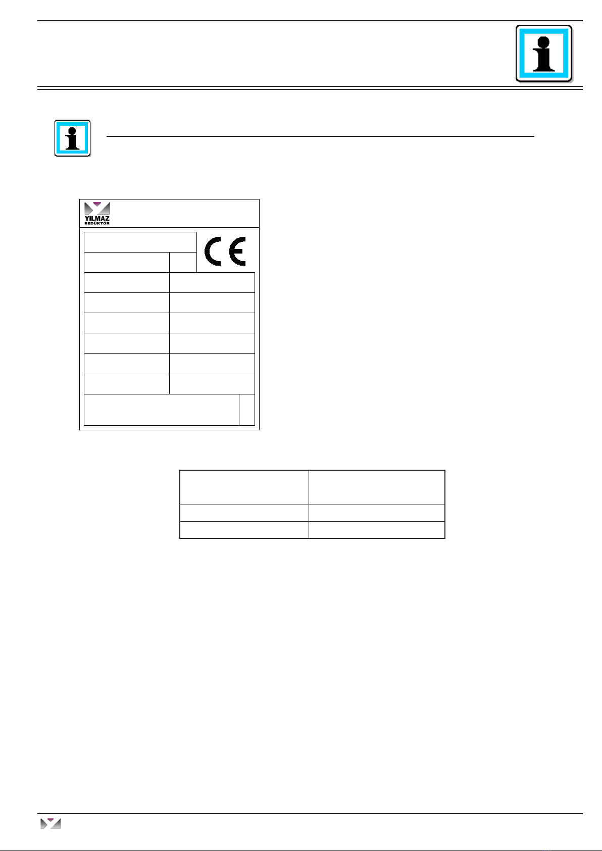
2.2- Nameplate, Unit Designation ....................................................................................07
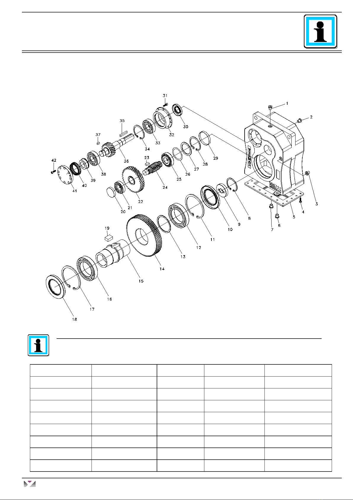
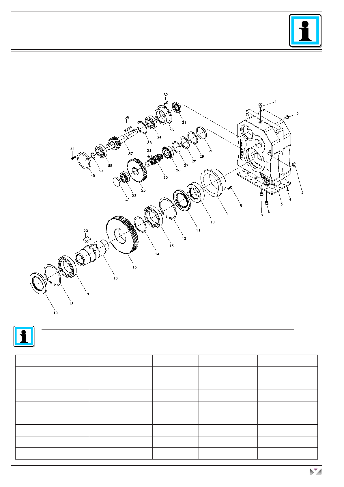
3. Standard Type Gearbox Parts Lists ..............................................................................08
3.1- TT..00 type ...............................................................................................................08
3.2- TT..00.K type ........................................................................................................09
3.3- TT..0S type............................................................................................................10
3.4- TT..0S.K type........................................................................................................ 11
4- Things to Check Before the Gear Unit or Geared Motor is Installed ...................... 12
4.1- Safety notes for use in potentially explosive atmosphere ...................................... 12
Intended use of Gearbox....................................................................................... 12
4.2- Transportation ........................................................................................................13
4.3- Storage...................................................................................................................13
5 - Installing the Gear Unit...............................................................................................14
5.1- Before You Start .....................................................................................................14
5.2- Check Name Plate of the Gear Unit ....................................................................... 14
5.3- Check the Ambient Conditions and Temperature .................................................. 14
5.4- Check Fitting Elements and the Shaft Dimensions to Fit ...................................... 14
5.5- Check the Voltage Supply ...................................................................................... 16
5.6- Check the Mounting Position..................................................................................16
5.7- Usage of Breather Plug.......................................................................................... 16
5.8- Check the oil level ..................................................................................................17
5.9- Check shaft ends and mounting faces ...................................................................17
5.10- Cover abrasive ambients......................................................................................17
5.11- Check accessibility to filling, breather and drain plugs......................................... 17
6- Mechanical Installation................................................................................................18
6.1- Installing gear units in category II2G/D-II3G/D.......................................................18
6.2- Installing Customer Shaft with Shoulder ................................................................ 19
6.3- Installing Customer Shaft without Shoulder ........................................................... 20
6.4- Disassembling Customer Shaft with Shoulder ....................................................... 21
6.5- Disassembling Customer Shaft without Shoulder .................................................. 22
6.6- Shaft Tightening Torques ....................................................................................... 23
6.7- Recommended Shaft Dimensions and Mounting Washer Dimensions.................. 24
6.8- Assembling customer shaft with shrink disk...........................................................25
Operating Instructions
T Series
YILMAZ REDÜKTÖR
Contents

3
6.9- Disassembling customer shaft with shrink disk...................................................... 27
6.10- Assembling Gear Unit with Tightening Arm..........................................................28
6.11- Fixing Holes Dimensions...................................................................................... 30
6.12- Fitting input shaft elements .................................................................................. 31
6.13- Correct position of input shaft elements............................................................... 31
6.14- Fitting couplings ..................................................................................................32
7- Maintenance and Inspections .................................................................................... 33
8- Lubrication ...................................................................................................................34
8.1- Oil types .................................................................................................................34
8.2- Changing the oil ..................................................................................................... 35
8.3- Oil quantities (lt) .....................................................................................................35
8.4- Oil plugs .................................................................................................................36
8.5- Mounting Positions................................................................................................. 37
9- Troubleshooting Guide................................................................................................ 38
10- Appendix.......................................................................................................................
10.1- Warranty Conditions....................................................................................................
10.2- Warranty Decleration...................................................................................................
10.3- Service Contact Points................................................................................................
Operating Instructions
T Series
YILMAZ REDÜKTÖR
Contents

4
Operating Instructions
T Series
YILMAZ REDÜKTÖR

5
1 - How to Use This Manual
Take attention to the following safety and warning signs for proper understanding and quick reference.
Electrical Hazard; Can cause severe or fatal injuries.
Mechanical Hazard; Can cause severe or fatal injuries.
Likely to be Hazardous; Can cause minor or fatal injuries
Damage Risk; Can damage the gearbox or environment
Important Information
Important information about explosion protection
The operating instructions contain important information to ensure ;
- Trouble-free operation
- Fulfilment of any rights to claim under guarantee
The operating instruction must be kept close to the gearbox and must be available in case it is
needed.
This operating instruction is written for T series gear units and is applicable only for these series. If
any different type of gear unit is used please ask YILMAZ REDUKTOR. For special application and
modified gear units ask YILMAZ REDUKTOR for validity.
The T series gear units are with input shaft and without motor. The electric motor which will be con-
nected to the gear unit must also be in conformity with the ATEX (94/9/EC) standards.
All the external parts which will be assembled to the gear unit must conform ATEX (94/9/EC). The
product this declaration refers to must not be put into service until the machinery into which it is to be
incorporated has been declared in conformity with the provisions of the relevant European Directives.
If the gear unit is not operated as informed on this manual the gear unit is no longer ATEX conforming
and YILMAZ REDUKTOR does not take any responsibility.
o
Operating Instructions
T Series
YILMAZ REDÜKTÖR
General Informations

6
2 - Unit Designation
2.1- Detailed Unit Designation
Detailed T series gear units designation for ordering
(This Designation is different from the short nameplate designation)
TT 57 . 00 . K - M1
Serie of gear unit
TT : Two stage helical gear unit
Gear unit size
Sizes from 17 to 97
Output hollow shaft diameter
00 : Standart hollow shaft diameter
0X : Special hollow shaft diameter
0S : Hollow shaft with shrink disc
Backstop option
K :Backstop is avaliable
-: Backtop is unavaliable
Mounting Position
M1 : Gear unit is upright and input shaft is over output shaft
M2 : Input shaft is vertical to earth and input shaft points to sky
M3 : Gear unit is upright and input shaft is under output shaft
M4 : Input shaft is vertical to earth and input shaft points to earth
M5 : Input and output shaft is paralel to earth, input shaft is under
M6 : Input and output shaft is paralel to earth, input shaft is over
Operating Instructions
T Series
YILMAZ REDÜKTÖR
Unit Designation

7
2.2- Nameplate, unit designation
Nameplate unit designation is a short abbreviation from the detailed designation
A sample name plate for T Series according to 94/9/EC
Category of Gear Unit
(in acc. to 94/9/EC)
Intended use in Zones
(in acc. of 1999/92/EC)
2GD 1; 21; 2; 22
3GD 2; 22
12
-20/+40
a
TºC
M.Pos.:
II 2GD IIB c k T4 / T120 ºC
FA1
N
FA2
Oil Qty:
R2
FR1
NF
N
lt.
N
Type:
M
kW
P
nrpm. n
2
S/N. :
Nm.
rpm.
:
:
:
:
:
:
:
:
:
:
IP65
YILMAZ REDÜKTÖR A.S.
ATATÜRK Mah. Lozan Cad. No:17 P.K.34522
Esenyurt-İstanbul- TÜRKİYE
TT57.00.K/ 2GD
100478985
11
1400
4850
85
42500 1500
37500 500
5.3
MINERAL VG320
M1
Abbreviations:
Type. : Type of gearbox
S/N: Serial Number of gear unit ;
IP..: Enclosure
P: Max. Allowed Power
M : Output torque
n : Input speed
n : Output speed
FR : Max. allowed radial load at output shaft
FR : Max. allowed radial load at input shaft
FA: Max. allowed axial load at output shaft
FA: Max. allowed axial load at input shaft
Oil : Filled oil inside the gear unit
Qty. : Oil quantity
M.pos.: Mounting Position.
Ta : Ambient Temp.
Operating Instructions
T Series
YILMAZ REDÜKTÖR
Unit Designation

8
3.1- TT...00 Types
3. Standard Type Gearbox Part Lists
1- Plug 10- Oil Seal 19- Key 28- Circlip 37- Bearing
2- Plug 11- Circlip 20- Closing Cap 29- Closing Cap 38- Circlip
3- Plug 12- Bearing 21- Bearing 30- Oil Seal 39- Back Cover
4- Bolt 13- Washer 22- Gear 31- Bolt 40- Bolt
5- Cover Plate 14- Gear 23- Key 32- Input Shaft Cover
6- Plug 15- Output Hollow Shaft 24- Pinion 33- Bearing
7- Plug 16- Bearing 25- Bearing 34- Circlip
8- Circlip 17- Circlip 26- Shim 35- Key
9- Mounting Washer 18- Oil Seal 27- Washer 36- Input Pinion Shaft
Standard TT...00 type basic part diagram. Parts may differ for special applications.
Standard Part List
Operating Instructions
T Series
YILMAZ REDÜKTÖR
Part Designations

9
3.2- TT...00.K Types
1- Plug 10- Oil Seal 19- Key 28- Circlip 37- Key
2- Plug 11- Circlip 20- Closing Cap 29- Closing Cap 38- Bearing
3- Plug 12- Bearing 21- Bearing 30- Oil Seal 39- Backtop Innner Bush
4- Bolt 13- Washer 22- Gear 31- Bolt 40- Backstop
5- Cover Plate 14- Gear 23- Key 32- Input Shaft Cover 41- Backstop Cover
6- Plug 15- Output Hollow Shaft 24- Pinion 33- Bearing 42- Bolt
7- Plug 16- Bearing 25- Bearing 34- Circlip
8- Circlip 17- Circlip 26- Shim 35- Key
9- Mounting Washer 18- Oil Seal 27- Washer 36- Input Pinion Shaft
Standard TT...00.K type basic part diagram. Parts may differ for special applications.
Standard Part List
Operating Instructions
T Series
YILMAZ REDÜKTÖR
Part Designations

10
3.3- TT...0S Types
1- Plug 10- Shrink Disk 19- Oil Seal 28- Washer 37- Input Pinion Shaft
2- Plug 11- Oil Seal 20- Key 29- Circlip 38- Bearing
3- Plug 12- Circlip 21- Closing Cap 30- Closing Cap 39- Circlip
4- Bolt 13- Bearing 22- Bearing 31- Oil Seal 40- Back Cover
5- Cover Plate 14- Washer 23- Gear 32- Bolt 41- Bolt
6- Plug 15- Gear 24- Key 33- Input Shaft Cover
7- Plug 16- Output Hollow Shaft 25- Pinion 34- Bearing
8- Bolt 17- Bearing 26- Bearing 35- Circlip
9- Shrink Disk Protec. Cover 18- Circlip 27- Shim 36- Key
Standard TT...0S type basic part diagram. Parts may differ for special applications.
Standard Part List
Operating Instructions
T Series
YILMAZ REDÜKTÖR
Part Designations

11
3.4- TT...0S.K Types
1- Plug 10- Shrink Disk 19- Oil Seal 28- Washer 37- Input Pinion Shaft
2- Plug 11- Oil Seal 20- Key 29- Circlip 38- Key
3- Plug 12- Circlip 21- Closing Cap 30- Closing Cap 39- Bearing
4- Bolt 13- Bearing 22- Bearing 31- Oil Seal 40- Backstop Inner Bush
5- Cover Plate 14- Washer 23- Gear 32- Bolt 41- Backstop
6- Plug 15- Gear 24- Key 33- Input Shaft Cover 42- Backstop Cover
7- Plug 16- Output Hollow Shaft 25- Pinion 34- Bearing 43- Bolt
8- Bolt 17- Bearing 26- Bearing 35- Circlip
9- Shrink Disk Protec. Cover 18- Circlip 27- Shim 36- Key
Standard TT...0S.K type basic part diagram. Parts may differ for special applications.
Standard Part List
Operating Instructions
T Series
YILMAZ REDÜKTÖR
Part Designations

12
4- Things to Check Before the Gear Unit or Geared Motor is Installed
4.1- Safety notes for use in potentially explosive atmosphere
Explosive gas mixtures or concentration of dust can lead to severe or fatal injuries in
conjunction with hot or moving parts of the gear unit / geared motor.
Before you install the gearbox you have to be sure that the gearbox is arrived with the all
necessary equipment and without damage. Things to take into consideration before you
start to install the unit ;
- You have received the correct operation manual of your product.
- The gearbox and all it’s parts are transported without damage.
- The gearbox is stored correctly according the instructions in this manual.
- The nameplate is clearly visible and all data can be read.
- All the regulations and requirements are according to the currently valid
national / regional regulations.
- The gearbox is used according it’s intended use.
Intended use of Gearbox
The gearboxes covered by this manual can only be used in ATEX zone 2G, 2D, 3G, 3D
and ignition class IIA / IIB.
The gear units are intended for industrial systems and may only be used in accordance
the information provided in this manual and the nameplate of the gearbox. They comply
with the applicable standards and regulations and meet the requirements of the directive
94/9/EC. The gearbox is started up, maintained and operated according this manual. The
gearbox is incorporated with 94/9/EC confirming parts / machines.
A motor connected to the gear unit is only allowed to be operated in the frequency entries
so that the data provided on nameplate of the gear unit is not exceeded and is accord-
ance with the nameplate. The input speed range will be provided on the nameplate if
YILMAZ REDUKTOR is informed that the gear unit will be used with frequency inverter. If
not informed the nameplate will have a single fixed input speed and only this input speed
is allowed. The electric motor and frequency inverter must be in accordance with 94/9/EC.
If the gear units input is used with variable speed gear unit, this must be informed to
YILMAZ REDUKTOR before ordering and on the nameplate the allowed maximum and
minimum input speeds (speed range) will be provided. If not mentioned during ordering
the gear units input speed will be a fixed single speed and only this speed is allowed.
If the gear unit will be driven by belt / coupling / chain drive etc. the gear unit is only al-
lowed to be used according the nameplate entries. Different speed, higher motor power,
higher radial / axial loads etc. than nameplate is not allowed.
The ambient conditions must be accordance with the nameplate and no aggressive media
must attack the paint and seals.
o
o
o
o
o
Operating Instructions
T Series
YILMAZ REDÜKTÖR
Installing

13
The gearbox maintenance (oil change / check) must be done according this manual.
4.2- Transportation
When the gearbox arrive, first check for any damage. If some damage observed, im-
mediately contact the transport company and inform about damage. Contact YILMAZ
for the damage and do not start installing the gear unit until is is agreed that the dam-
age has no affect of operation.
Use the supplied eyebolts or lifting holes for lifting up the gear unit. The eyebolts are
capable to carry the weight of gearboxes only. Do not hang additional loads.
4.3- Storage
If the geared unit or geared motor will be stored up to 3 years refer to the following
instructions ;
With Packing ;
- Use corrosion protection oil for the output shaft and connection surfaces like flange
surface or foot assembling surface. Seal the unit in a plastic wrap and pack it in con-
tainer. A moisture indicator should be placed around the container to observe the mois-
ture. Relative atmospheric humidity should not exceed 50%. The container should be
kept under roof which protects from snow and rain. Under this condition the gear unit
can be stored up to 3 years with regular check.
Without Packing ;
- Use protection oil for the output shaft and connection surfaces like flange surface or
foot assembling surface. If no packing is used and the gearbox is stored without pack-
ing, the ambient temperature should be between 5 to 60 Celsius degrees. The gearbox
must be kept under enclosed roof with constant temperature and constant humidity not
exceeding 50%. The storage should be free of dust and dirt and ventilated with filter. If
the gearbox is stored without packing it is recommended not to store more than 2 years
and regularly checking is recommended during this time.
If stored in open protect against insect damage.
o
Operating Instructions
T Series
YILMAZ REDÜKTÖR
Installing

14
5- Installing the Gear Unit
5.1- Before you start ;
- Observe the gear unit for damages of storage or transportation. If there is any dam-
age please contact YILMAZ REDUKTOR.
- Be sure that you have all the necessary equipment for installing like ; spanners,
torque wrench, shims and distance rings, fixing devices for input and output ele-
ments, lubricant, bolt adhesive / locktide etc.
5.2- Check Nameplate of the Gear Unit ;
- ATEX conforming gear units have a nameplate indicating the ‘‘o’’ sign shown on
the left side and the following information ;
- Equipment group
- Ex category
- Ex zone
- Temperature class
- Maximum surface temperature
If you can not see this sign and values, your gearbox is not intended for use on po-
tentially explosive atmosphere. If some of the data can not be read because of some
reason, please contact YILMAZ REDUKTOR.
5.3- Check the Ambient Conditions and Temperature ;
Have measures been taken to ensure that no potentially explosive atmosphere, oils,
acids, gases, vapors or radiated interference are present when the gear unit is being
installed. The ambient temperature must be in accordance with the oil tables given
on the manual. If it is different contact YILMAZ REDUKTOR for special solutions.
The ambient air temperature must not exceed 40 degrees celcius as mentioned on
the nameplate. The cooling air surrounding the gear unit must below 40 degrees and
the gear unit must not subject to heating from external sources. The gear unit surface
must be kept clean and sufficiently ventilated.
Total thickness of all paintings and coatings on gear unit must be smaller then 2 mm.
Please contact us before making additional paintings or coatings on gear unit.
5.4- Check Fitting Elements and the Shaft Dimensions to Fit;
All external elements that will be fitted to the gear unit must be ATEX conforming.
The shaft / flange dimensions are shown on next page. Use correct tolerances to fit
external elements. Observe the assembly instructions provided in this manual.
Only belts with sufficient shunt resistance <10^9 ohm are allowed.’
o
o
o
o
Operating Instructions
T Series
YILMAZ REDÜKTÖR
Installing

15
Never strike belt pulleys, coupling, pinions etc. with a hammer when pulling them onto
the shaft end. This could result in damage to bearings, the housing and the shaft.
Power transmission elements must be balanced after fitting and must not give rise to
any permissible radial or axial forces.
Observe the nameplate for maximum allowed radial and axial load. The external ra-
dial and axial load must not exceed the provided values on the nameplate.
o
Type
Input Shaft
Diameter
[mm]
Tolerance
Hollow Shaft
Diameter
[mm]
Tolerance
(DIN 748)
(G7)
Hollow Shaft
Diameter with
Shrink Disk
Tolerance
(DIN 748)
(H7)
Customer
Shaft
Diameter
for Shrink
Disk
Tolerance
(DIN 748)
(h6)
TT17.00 19 +0.02
030 +0.03
+0.01 30 +0.02
030 0
-0.01
TT27.00 19 +0.02
035 +0.03
+0.01 35 +0.03
035 0
-0.02
TT28.00 24 +0.02
040 +0.03
+0.01 40 +0.03
040 0
-0.02
TT37.00 24 +0.02
045 +0.03
+0.01 45 +0.03
045 0
-0.02
TT47.00 28 +0.02
050 +0.03
+0.01 50 +0.03
050 0
-0.02
TT57.00 38 +0.02
060 +0.04
+0.01 60 +0.03
060 0
-0.02
TT67.00 42 +0.02
070 +0.04
+0.01 70 +0.03
070 0
-0.02
TT77.00 48 +0.02
080 +0.04
+0.01 80 +0.03
080 0
-0.02
TT87.00 55 +0.03
+0.01 100 +0.05
+0.01 100 +0.04
0100 0
-0.02
TT97.00 55 +0.03
+0.01 125 +0.05
+0.01 125 +0.04
0125 0
-0.03
Operating Instructions
T Series
YILMAZ REDÜKTÖR
Installing

16
5.5- Check the Voltage Supply ;
ATEX conforming gear units are supplied by YILMAZ without motor. The motor that will be
fitted must have ATEX certificate and the instruction manual of the electric motor provider
must be observed. Observe the name plate of the electric motor and the instructions of
the supplier. Use experienced electric technician. The gearbox and the motor must be
grounded to prevent potential differences of earth and gearbox / motor.
Using wrong connection or voltage can damage the electric motor or environment. The
electric connection must be done by experienced electric technician.
The gearbox and the motor must be grounded to prevent potential difference of earth and
gearbox / motor after installation before starting up.
5.6- Check the Mounting Position ;
The mounting position must be in accordance with the mounting position mentioned on the
name plate. If different please contact YILMAZ REDUKTOR for possibilities of using in a
different mounting position then indicated on the name plate without informing YILMAZ
REDUKTOR will cancel the ATEX conformity and YILMAZ does not take any
responsibility.
Do not mix synthetic oils with mineral oils which can cause serious damage on the gear
unit.
5.7- Usage of Breather Plug ;
Breather plugs are supplied as a standard part for ATEX conforming gear units. The
breather plug is attached to the gear unit and must be changed with the most top plug ac-
cording to the mounting position. Take out the plug over the gear box and replace it with
the supplied breather plug after assembling to its place and before start-up.
The breather plugs are opened at 0.2 bar pressure.
After opening the plugs use Locktite when locking them again.
All plug points are not machined. Only plugs according mounting position is machined. If
no mounting position is mentioned by ordering the standard M1 position plugs are
machined.
o
o
o
Operating Instructions
T Series
YILMAZ REDÜKTÖR
Installing

17
5.8- Check the oil level ;
On the mounting position tables the oil level plug is shown. Please refer to those
tables and be sure that the oil level is correct according the mounting position. Use
a wire as shown below for checking the oil level entering from the level plug. The oil
level must be within 3mm from the plugs entering point as shown below. If you need
to adjust the oil level refer to the oil tables given on this manuel and be sure you are
using the correct oil. Observe the nameplate for the correct oil.
After checking the oil level of gear unit tighten the screws very carefully to prevent oil
leakage.
Do not mix synthetic oils with mineral which can cause serious damage on the
gear unit.
5.9- Check shaft ends and mounting faces;
Before you start to installing be sure that all the connection elements are free of oil
and dust. The output shaft may be protected by anti-corrosion oil. Please remove this
using available solvents on your market. By using this do not touch sealing lips or
painting of the housing.
5.10- Cover abrasive ambient;
If the gear unit will be placed on a abrasive ambient be sure that the output seals
are covered so that no abrasive material, chemicals or water touches the seals. Any
pressure coming from outside over the seals can cause that the out staying sub-
stances to enter the gearbox and cause serious damage to the gear unit. If pressure
or abrasive material can not be prevented from
coming over the sealing, contact YILMAZ for solutions.
Abrasive material, chemicals, water, positive or negative pressure exceeding 0,2 bar
can affect or damage the sealing lip or output shaft. Inside entering substances from
the seals can cause serious damage to the gear unit.
To avoid temperature rising in case of dust cover on the housing of the gearbox, the
housing have to be cleaned regularly.
5.11- Check accessibility to filling, breather and drain plugs;
The filling, breather and drain plugs must be freely accessible for further checking
and service.
o
o
Operating Instructions
T Series
YILMAZ REDÜKTÖR
Installing

18
6- Mechanical Installation
The mounting plate must be rigid enough not allowing torsions, flat enough to prevent
strains by tightening the bolts and stable enough not allowing vibrations. By using chain
drives this becomes much more important because of the polygon effect on chain drives.
According to your connection elements the maximal permitted radial and axial load of the
gear unit must be in accordance with your application. Check the product catalogue for
permitted radial loads and calculation.
If the output or input shaft is overloaded by radial or axial loads it can cause serious dam-
age to the gear unit.
Secure the gear unit using 8.8 or higher quality bolts.
All bolts are locked by use of locktide adhesives or gear-shims on the gearbox. By assem-
bling the gear unit locktides adhesives or gear-shims must be used to prevent loosening
of bolts.
Cover all the turning parts from human entering or touching. Turning parts can cause se-
vere or fatal injuries.
For different kind of basic installations refer to the following illustrations.
Only ATEX-approved input and output elements are allowed to be used, assuming the ele-
ments are subject to Directive 94/9/EC
6.1- Installing gear units in category II2G/D-II3G/D
Explosion-proof gear units comply with the design requirements for unit group II, catagory
2G,2D,3D,3G. These units are intended for use in zones 1 and 21.
The gear units in catagory II2D must be used in ambient teperature between -20 C to +40
C only. If different ambient conditions this must be informed before order and the name
plate must be in accordance with the ambient conditions.
The temperature class depends on the speed, type and mounting position of the gearbox
and is indicated on the name plate. Temperature classes from T4 to T6 are provided by
YILMAZ REDUKTOR.
The surface temperature of the gearbox must not exceed the provided max. surface tem-
perature on the name plate. After all installations finished and the gearbox is started up
according this manual let the gear unit run 4 hours at full load and check the surface tem-
perature and the ambient temperature. Check the following;
(40-Ta)+Tw < Tmax. of nameplate ( Ta: Ambient Temp., Tw: Surface Temp)
o
o
o
o
o
Operating Instructions
T Series
YILMAZ REDÜKTÖR
Installing

19
If the result is higher then Tmax, immediately stop the system and contact
YILMAZ REDUKTOR.
o
6.2.2- Fasten the bold as shown below.
6.2- Installing Customer Shaft with Shoulder
6.2.1- Use anti-seize assembling paste available on your market. Use a
brush to apply the paste.
1- Bolt
2- Lock Washer
3- Circlip
4- Mounting Washer
5- Hollow Shaft
6- Customer Shaft
Operating Instructions
T Series
YILMAZ REDÜKTÖR
Installing

20
6.3- Installing customer shaft without shoulder
6.3.1- Use anti-seize mounting paste available on your market. Use a brush to
apply the paste.
6.3.2- Fasten the bolt as shown below.
1- Bolt
2- Lock Washer
3- Circlip
4- Mounting Washer
5- Hollow Shaft
6- Customer Shaft
Operating Instructions
T Series
YILMAZ REDÜKTÖR
Installing
This manual suits for next models
10
Table of contents
Other YILMAZ REDÜKTÖR Industrial Equipment manuals
Popular Industrial Equipment manuals by other brands

PAW
PAW HeatBloC K34R Installation and operation instruction

Nordson
Nordson MELTEX PG Series manual

Reliable
Reliable DDX-LP PrePak Instructions for installation, operation care and maintenance

Eaton
Eaton Magnum DS instructions

ABB
ABB HT592011 Operation manual

Curt Manufacturing
Curt Manufacturing 48626 installation manual