YILMAZ REDÜKTÖR H Series User manual

H Series
İndustrial Type Gear Units
OPERATING
INSTRUCTIONS
OIHCE0601/0121

2
Contents............................................................................................................................02
1 - How to Use This Manual.............................................................................................05
2 - Unit Designation..........................................................................................................06
2.1- Detailed Unit Designation.......................................................................................06
2.2- Nameplate, Unit Designation ....................................................................................07
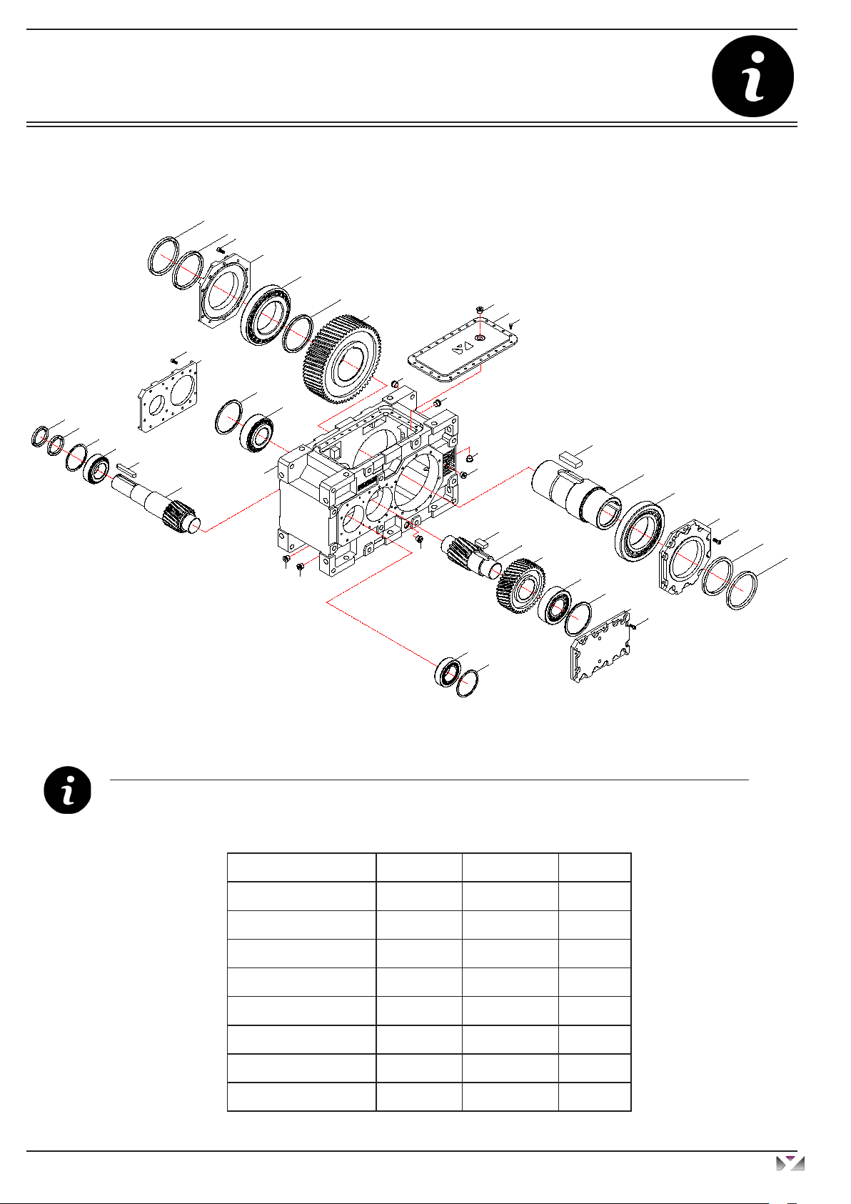
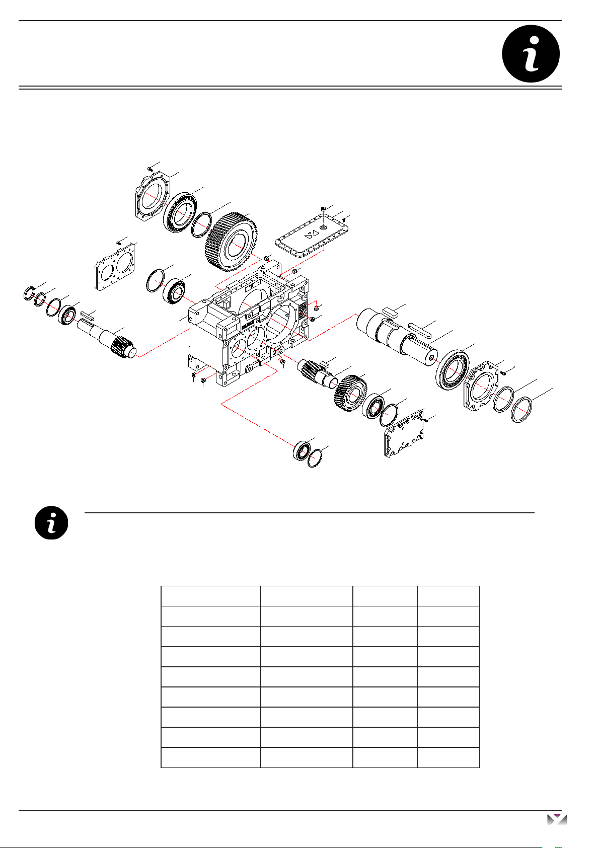
3. Standard Type Gearbox Parts Lists ..............................................................................08
3.1- HT..2.00 type............................................................................................................08
3.2- HT..2.0S type ........................................................................................................09
3.3- HT..2.01 type.........................................................................................................10
3.4- HT..2.02 type......................................................................................................... 11
3.5- HT..2.03 type.........................................................................................................12
3.6- HT..2.04 type.........................................................................................................13
3.7- HT..2.05 type.........................................................................................................14
3.8- HT..2.08 type.........................................................................................................15
3.9- HTE.2.0E type .........................................................................................................16
3.10- HT..3.00 type........................................................................................................17
3.11- HT..3.0S type .......................................................................................................18
3.12- HT..3.01 type........................................................................................................19
3.13- HT..3.02 type........................................................................................................20
3.14- HT..3.03 type........................................................................................................21
3.15- HT..3.04 type........................................................................................................22
3.16- HT..3.05 type........................................................................................................23
3.17- HT..3.08 type........................................................................................................24
3.18- HTE.3.0E type .....................................................................................................25
3.19- HT..4.00 type........................................................................................................26
3.20- HT..4.0S type ..........................................................................................................27
3.21- HT..4.01 type........................................................................................................28
3.22- HT..4.02 type........................................................................................................29
3.23- HT..4.03 type........................................................................................................30
3.24- HT..4.04 type........................................................................................................31
3.25- HT..4.05 type........................................................................................................32
3.26- HT..4.08 type........................................................................................................33
4- Safety ............................................................................................................................34
4.1- Intended use...........................................................................................................34
4.2- Improper use ..........................................................................................................34
4.3- Safety Instructions..................................................................................................35
4.3.1- General safety instructions............................................................................35
4.3.1.1- Working on the gearbox .....................................................................35
4.3.1.2- Operation ........................................................................................... 35
4.3.1.3- Maintenance .......................................................................................35
4.3.1.4- Lubrication...........................................................................................35
4.3.1.5- Working conditions .............................................................................35
Operating Instructions
H Series
YILMAZ REDÜKTÖR
Contents

3
4.4- Tightening torques....................................................................................................36
4.5- Case of fire....... ......................................................................................................36
4.5.1- Suitable extinguishers..................................................................................36
4.5.2- Unsuitable extinguishers..............................................................................36
5 - Checking Before Installing the Gearbox...................................................................37
5.1- Transportation ........................................................................................................ 37
5.2- Storage...................................................................................................................38
6- Installing the Gearbox .................................................................................................38
6.1- Before you start ......................................................................................................38
6.2- Checking shaft dimensions ...................................................................................39
6.3- Checking ambient temperatures ............................................................................39
6.4- Checking voltage supply ........................................................................................39
6.5- Checking mounting position ...................................................................................42
6.6- How to use breather plug .......................................................................................42
6.7- Checking oil level ...................................................................................................42
6.8- Checking shaft ends and mounting faces ..............................................................42
6.9- Protection from corrosive environment...................................................................42
6.10- Checking accessibility to oil plugs........................................................................43
7- Mechanical Installation ...............................................................................................43
7.1- Installing customer shaft with shoulder .......................................................................44
7.2- Disassembling customer shaft with shoulder ......................................................... 45
7.3- Installing output shaft elements .............................................................................47
7.4- Correct position of output shaft elements...............................................................47
7.5- Coupling connection...............................................................................................48
7.6- Shaft tightening torques .........................................................................................49
7.7- Recommended shaft dimensions for B.00 types.................................................... 50
8- Maintenance & Inspection ..........................................................................................51
9- Lubrication ...................................................................................................................52
9.1- Oil types .................................................................................................................52
9.2- Changing the oil .....................................................................................................53
9.3- Oil quantities (lt) .....................................................................................................53
9.4- Oil plugs .................................................................................................................54
9.5- Mounting Positions.................................................................................................56
Operating Instructions
H Series
YILMAZ REDÜKTÖR
Contents

4
10- Cooling Options..........................................................................................................57
10.1- Fan cooling...............................................................................................................58
10.2- Cooling with cooling coil...........................................................................................58
10.3- Cooling with water / oil heat exchanger....................................................................59
10.4- Cooling with air / oil heat exchanger.........................................................................60
11- Troubleshooting Guide..................................................................................................61
12- Disposal.......................................................................................................................64
12.1- Disposal of oil........................................................................................................... 64
12.2- Disposal of sealing....................................................................................................64
12.3- Disposal of metal parts..............................................................................................64
13- Appendix......................................................................................................................65
13.1- Warranty conditions...................................................................................................66
13.2- Warranty paper..........................................................................................................67
13.3- Service points............................................................................................................68
Operating Instructions
H Series
YILMAZ REDÜKTÖR
Contents

5
1 - How to Use This Manual
Take attention to the following safety and warning signs for proper understanding and quick reference.
Electrical Hazard; Can cause severe or fatal injuries.
Mechanical Hazard; Can cause severe or fatal injuries.
Likely to be Hazardous; Can cause minor or fatal injuries
Damage Risk; Can damage the gearbox or environment
Important Information
EC Machinery Directive:
Within terms of the EC machinery directive 2006/42/EC ,the gear reducer is not
considered an autonomous machine, but as a component to install in machines.
Operation is prohibited within the area of validity of the EC directive, until it has been
determined that the machine, in which this product is installed, corresponds to the
regulations within this directive.
The operating instructions contain important information to ensure;
- Trouble-free operation
- Fulfilment of any rights to claim under guarantee
The operating instruction must be kept close to the gearbox and must be available in
case it is needed.
This operating instruction is written for H series gear units and is applicable only for H
series. If any different type of gearbox is used please ask YILMAZ REDUKTOR for the
operating instructions of that type.
This instruction can be used only for standard type geared units of YILMAZ
REDUKTOR. For special application and modified gear units ask YILMAZ REDUKTOR
for validity.
This manual does not cover 94/9/EC compatible gearboxes. For 94/9/EC contact
YILMAZ REDUKTOR.
Operating Instructions
H Series
YILMAZ REDÜKTÖR
General Informations

6
2 - Unit Designation
2.1- Detailed Unit Designation
Detailed H series gear units designation for ordering
(This Designation is different from the short nameplate designation)
Mounting Position
M1: Output shaft is parallel to earth, cover is on top
M2: Gearbox is upright and output shaft is over input shaft
M3: Output shaft is parallel to earth, cover is on bottom
M4: Gearbox is upright and output shaft is under input shaft
M5: While the output shaft perpendicular to the ground and the mounting cover is
on the front, the right side surface (Y1) faces downwards
M6: While the output shaft perpendicular to the ground and the mounting cover is
on the front, the left side surface (Y4) faces downwards
AX: Gearbox works in an angle
...T: with torque arm
IEC Motor Flange Size
Only for HK types
A13: IEC 132 B5 (300x265x230 mm)
A16: IEC 160 B5 (350x300x250 mm)
A18: IEC 180 B5 (350x300x250 mm)
A20: IEC 200 B5 (400x350x300 mm)
A22: IEC 225 B5 (450x400x350 mm)
A25: IEC 250 B5 (550x500x450 mm)
A28: IEC 280 B5 (550x500x450 mm)
A31: IEC 315 B5 (660x600x550 mm)
Output Shaft Properties
0: Hollow shaft
1: Solid output shaft
2: Solid output shaft and output flange
3: Hollow shaft and output flange
4: Double output shaft
5: Double output shaft and flange
8: Hollow output shaft and double output flange
S: Hollow shaft with shrink disk
E: Extruder type output
0A: Drywell gearbox with hollow output shaft
1A: Drywell gearbox with solid output shaft
SA: Drywell gearbox with shrink disk
H T 05 2 3 . 0 1 R - M1 / A28
Shaft and Flange Arrangement
Please refer to shaft and flange arrangements section at catalogue
Input Shaft Properties
0: Standard input shaft
1: Optional extruder type output
2: Double input shaft
Number of Gear Stages
2: Two stages
3: Three stages
4: Four stages
Revision Number
Second revision
Gearbox Size
Sizes from 03.......to 22
Version of Gearbox
T: Free solid input shaft
K: With IEC B5 flange and free input shaft
TE: Extruder type with free input shaft
KE: Extruder type with IEC B5 flange and free input shaft
TB: Drywell gearbox with free solid input shaft
KE: Drywell gearbox with IEC B5 flange and free solid input shaft
Serie of Gear Unit
H: Helical gear type horizontal industrial gear units
B: Helical gear type horizontal industrial gear units with bevel stage input
Operating Instructions
H Series
YILMAZ REDÜKTÖR
Unit Designation

7
2.2- Nameplate, unit designation
Nameplate unit designation is a short abbreviation from the detailed designation
A sample name plate for H Series
Abbreviations:
Serial N. : Serial Number
M.Pos. : Mounting Position
Type Designation;
HT0323.00 R
Type
Serial Number: 100478985
Shaft and Flange Arrangement
Viewed from input side
L - Right input, Left output
R- Left input, Right output
U- Right input, Right output
V- Left input, Left output
Type:
Serial N.:
Power:
Speed:
Oil:
Oil Qty:
Ratio:
M.Pos.:
kW
rpm.
lt.
www.yr.com.tr
MADE IN TURKEY
YILMAZ REDÜKTÖR
HT0323.00R
22 20.73
M1
100478985
68
MINERAL VG460
8
Operating Instructions
H Series
YILMAZ REDÜKTÖR
Unit Designation

8
3.1- HT...2.00 Types
Standard HT...2.00 type basic part diagram. Parts may differ for special applications.
Standard Part List
3. Standard Type Gearbox Part Lists
1- Seal 10- Gear 19- Gear 28- Seal
2- Bolt 11- Spacer 20- Bearing
3- Seales Side Cover 12- Bearing 21- Spacer
4- Bearing 13- Bolt 22- Bearing
5- Hollow Output Shaft 14- Cover 23- Housing
6- Key 15- Spacer 24- Gear
7- Oil Plug 16- Bearing 25- Key
8- Bolt 17- Key 26- Bearing
9- Top Cover Plate 18- Gear 27- Spacer
7
8
9
7
1
1
2
3
4
5
6
10
11
12
3
1
2
1
7
7
7
13
14
15
20
19
18
17
16
15
14
13
77
7
23
21
22
24
25
26
27
28 28
Operating Instructions
H Series
YILMAZ REDÜKTÖR
Part Designations

9
3.2- HT...2.0S Types
Standard HT...2.0S type basic part diagram. Parts may differ for special applications.
Standard Part List
1- Shrink Disk 10- Top Cover Plate 19- Gear 28- Spacer
2- Seal 11- Gear 20- Gear 29- Seal
3- Bolt 12- Spacer 21- Bearing
4- Sealed Side Cover 13- Bearing 22- Spacer
5- Bearing 14- Bolt 23- Bearing
6- Hollow Output Shaft 15- Cover 24- Housing
7- Key 16- Spacer 25- Gear
8- Oil Plug 17- Bearing 26- Key
9- Bolt 18- Key 27- Bearing
8
22
23
25
26
27
28
29 29
2
2
3
4
5
1
9
10
8
6
7
11
12
13
4
2
3
2
8
8
8
14
15
16
21
20
19
18
17
16
15
14
88
8
24
Operating Instructions
H Series
YILMAZ REDÜKTÖR
Part Designations

10
3.3- HT...2.01 Types
Standard HT...2.01 type basic part diagram. Parts may differ for special applications.
Standard Part List
1- Seal 10- Top Side Cover 19- Key 28- Bearing
2- Bolt 11- Gear 20- Gear 29- Spacer
3- Sealed Side Cover 12- Spacer 21- Gear 30- Seal
4- Bearing 13- Bearing 22- Bearing
5- Shaft 14- Cover 23- Spacer
6- Key 15- Bolt 24- Bearing
7- Key 16- Cover 25- Housing
8- Oil Plug 17- Spacer 26- Gear
9- Bolt 18- Bearing 27- Key
5
7
4
1
1
2
3
6
8
9
10
8
11
12
13
14
2
8
8
8
15
16
17
22
21
20
19
18
17
16
15
88
8
25
23
24
26
27
28
29
30 30
Operating Instructions
H Series
YILMAZ REDÜKTÖR
Part Designations

11
3.4- HT...2.02 Types
Standard HT...2.02 type basic part diagram. Parts may differ for special applications.
Standard Part List
1- Output Flange 11- Oil Plug 21- Bearing 31- Bearing
2- Nut 12- Bolt 22- Key 32- Spacer
3- Screw Pin 13- Top Side Cover 23- Gear 33- Key
4- Seal 14- Gear 24- Gear
5- Bolt 15- Spacer 25- Bearing
6- Sealed Side Cover 16- Bearing 26- Spacer
7- Bearing 17- Cover 27- Bearing
8- Shaft 18- Bolt 28- Housing
9- Key 19- Cover 29- Gear
10- Key 20- Spacer 30- Key
1
2
3
8
10
7
4
4
5
6
9
12
13
14
15
16
17
5
18
19
20
25
24
23
22
21
20
19
18
11
11
11
11
11
11 11
11
28
26
27
29
30
31
32
33 33
Operating Instructions
H Series
YILMAZ REDÜKTÖR
Part Designations

12
3.5- HT...2.03 Types
Standard HT...2.03 type basic part diagram. Parts may differ for special applications.
Standard Part List
1- Output Flange 10- Oil Plug 19- Bearing 28- Key
2- Nut 11- Bolt 20- Key 29- Bearing
3- Screw Pin 12- Top Side Cover 21- Gear 30- Spacer
4- Seal 13- Gear 22- Gear 31- Seal
5- Bolt 14- Spacer 23- Bearing
6- Sealed Side Cover 15- Bearing 24- Spacer
7- Bearing 16- Bolt 25- Bearing
8- Hollow Output Shaft 17- Cover 26- Housing
9- Key 18- Spacer 27- Gear
11
12
10
4
4
5
6
7
8
9
13
14
15
6
4
5
4
10
10
10
16
17
18
23
22
21
20
19
18
17
16
10 10
10 1
2
3
26
24
25
27
28
29
30
31 31
10
Operating Instructions
H Series
YILMAZ REDÜKTÖR
Part Designations

13
3.6- HT...2.04 Types
Standard HT...2.04 type basic part diagram. Parts may differ for special applications.
Standard Part List
1- Seal 10- Top Side Cover 19- Gear 28- Spacer
2- Bolt 11- Gear 20- Gear 29- Seal
3- Sealed Side Cover 12- Spacer 21- Bearing
4- Bearing 13- Bearing 22- Spacer
5- Shaft 14- Bolt 23- Bearing
6- Key 15- Cover 24- Housing
7- Key 16- Spacer 25- Gear
8- Oil Plug 17- Bearing 26- Key
9- Bolt 18- Key 27- Bearing
5
7
6
9
10
8
11
12
13
3
2
8
8
8
14
15
16
21
20
19
18
17
16
15
14
88
8
2
3
4
1
1
6
22
23
25
26
27
28
29 29
11
24
8
Operating Instructions
H Series
YILMAZ REDÜKTÖR
Part Designations

14
3.7- HT...2.05 Types
Standard HT...2.05 type basic part diagram. Parts may differ for special applications.
Standard Part List
1- Output Flange 9- Key 17- Bolt 25- Spacer
2- Nut 10- Key 18- Cover 26- Bearing
3- Screw Pin 11- Oil Plug 19- Spacer 27- Housing
4- Seal 12- Bolt 20- Bearing 28- Gear
5- Bolt 13- Top Side Cover 21- Key 29- Key
6- Seal 14- Gear 22- Gear 30- Bearing
7- Bearing 15- Spacer 23- Gear 31- Spacer
8- Shaft 16- Bearing 24- Bearing 32- Seal
8
10
9
5
6
7
4
4
9
11
1
2
3
3
2
1
12
13
11
14
15
16
6
5
11
11
11
17
18
19
24
23
22
21
20
19
18
17
11 11
11
44
27
25
26
28
29
30
31
32 32
Operating Instructions
H Series
YILMAZ REDÜKTÖR
Part Designations

15
3.8- HT...2.08 Types
Standard HT...2.08 type basic part diagram. Parts may differ for special applications.
Standard Part List
1- Output Flange 10- Oil Plug 19- Bearing 28- Key
2- Nut 11- Bolt 20- Key 29- Bearing
3- Screw Pin 12- Top Side Cover 21- Gear 30- Spacer
4- Seal 13- Gear 22- Gear 31- Seal
5- Bolt 14- Spacer 23- Bearing
6- Sealed Side Cover 15- Bearing 24- Spacer
7- Bearing 16- Bolt 25- Bearing
8- Hollow Output Shaft 17- Cover 26- Housing
9- Key 18- Spacer 27- Gear
26
11
12
10
4
4
5
6
7
8
9
13
14
15
6
4
5
4
10
10
10
16
17
18
23
22
21
20
19
18
17
16
10 10
10
1
2
3
3
2
1
10
24
25
27
28
29
30
31 31
Operating Instructions
H Series
YILMAZ REDÜKTÖR
Part Designations

16
3.9- HTE..2.0E Types
Standard HTE..2.0E type basic part diagram. Parts may differ for special applications.
Standard Part List
1- Bolt 10- Extruder Housing 19- Bolt 28- Sealed Side Cover 37- Gear 46- Bearing
2- Cover 11- Nut 20- Top Side Cover 29- Bolt 38- Bearing 47- Spacer
3- Bolt 12- Screw Pin 21- Oil Plug 30- Seal 39- Side Cover 48- Seal
4- Seal Cover 13- Bearing 22- Gear 31- Bolt 40- Side Cover
5- Seal 14- Hollow Output Shaft 23- Spacer 32- Cover 41- Spacer
6- Extruder Shaft 15- Key 24- Bearing 33- Spacer 42- Bearing
7- Key 16- Plug 25- Spacer 34- Bearing 43- Housing
8- Axial Bearing 17- Cooling Coil 26- Locking Plate 35- Gear 44- Gear
9- Bolt 18- Bolt 27- Locking Nut 36- Key 45- Key
43
1
2
3
4
5
6
7
8
9
10
11
12
13
14
15
17
18
19
20
21
16
16
22
23
24
25
26
27
28
3029
31
32 33
34
3536
37
38
33
31
31
40
41
42
39
44
45
46
47
48
48
21
21
21
21
21
21
Operating Instructions
H Series
YILMAZ REDÜKTÖR
Part Designations

17
3.10- HT...3.00 Types
Standard HT...3.00 type basic part diagram. Parts may differ for special applications.
Standard Part List
1- Seal 10- Gear 19- Bearing 28- Bearing 37- Tube
2- Bolt 11- Spacer 20- Spacer 29- Spacer
3- Sealed Side Cover 12- Bearing 21- Bolt 30- Seal
4- Bearing 13- Cover 22- Spacer 31- Spacer
5- Hollow Output Shaft 14- Spacer 23- Bearing 32- Bearing
6- Key 15- Bearing 24- Gear 33- Key
7- Oil Plug 16- Gear 25- Key 34- Gear
8- Bolt 17- Key 26- Gear 35- Housing
9- Top Side Cover 18- Gear 27- Spacer 36- Bearing
8
9
7
7
7
35
77
7
7
71
1
2
3
4
5
6
10
11
12
3
2
1
1
13
14
15
16 17
18
19
20
21
13
22
23
24
25
26
27
28
29
21
30303132 33
34
36
37
Operating Instructions
H Series
YILMAZ REDÜKTÖR
Part Designations

18
3.11- HT...3.0S Types
Standard HT...3.0S type basic part diagram. Parts may differ for special applications.
Standard Part List
1- Shrink Disk 10- Top Side Cover 19- Gear 28- Spacer 37- Bearing
2- Seal 11- Gear 20- Bearing 29- Bearing 38- Tube
3- Bolt 12- Spacer 21- Spacer 30- Spacer
4- Sealed Side Cover 13- Bearing 22- Bolt 31- Seal
5- Bearing 14- Side Cover 23- Spacer 32- Spacer
6- Hollow Output Shaft 15- Spacer 24- Bearing 33- Bearing
7- Key 16- Bearing 25- Gear 34- Key
8- Oil Plug 17- Gear 26- Key 35- Gear
9- Bolt 18- Key 27- Gear 36- Housing
9
10
8
8
8
36
88
8
8
8
11
12
13
4
3
2
2
14
15
16
17 18
19
20
21
22
14
23
24
25
26
27
28
29
30
22
31313233 34
35
37
38
6
7
2
2
3
4
5
1
Operating Instructions
H Series
YILMAZ REDÜKTÖR
Part Designations

19
3.12- HT...3.01 Types
Standard HT...3.01 type basic part diagram. Parts may differ for special applications.
Standard Part List
1- Seal 10- Top Side Cover 19- Gear 28- Spacer 37- Bearing
2- Bolt 11- Gear 20- Bearing 29- Bearing 38- Tube
3- Sealed Side Cover 12- Spacer 21- Spacer 30- Spacer
4- Bearing 13- Bearing 22- Bolt 31- Seal
5- Shaft 14- Side Cover 23- Spacer 32- Spacer
6- Key 15- Spacer 24- Bearing 33- Bearing
7- Key 16- Bearing 25- Gear 34- Key
8- Oil Plug 17- Gear 26- Key 35- Gear
9- Bolt 18- Key 27- Gear 36- Housing
5
7
4
1
1
2
3
6
9
10
8
8
8
36
88
8
8
8
11
12
13
3
2
14
15
16
17 18
19
20
21
22
14
23
24
25
26
27
28
29
30
22
31313233 34
35
37
38
Operating Instructions
H Series
YILMAZ REDÜKTÖR
Part Designations

20
3.13- HT...3.02 Types
Standard HT...3.02 type basic part diagram. Parts may differ for special applications.
Standard Part List
1- Flange 10- Key 19- Bearing 28- Gear 37- Key
2- Nut 11- Oil Plug 20- Gear 29- Key 38- Gear
3- Screw Pin 12- Bolt 21- Key 30- Gear 39- Housing
4- Seal 13- Top Side Cover 22- Gear 31- Spacer 40- Bearing
5- Bolt 14- Gear 23- Bearing 32- Bearing 41- Tube
6- Sealed Side Cover 15- Spacer 24- Spacer 33- Spacer
7- Bearing 16- Bearing 25- Bolt 34- Seal
8- Shaft 17- Side Cover 26- Spacer 35- Spacer
9- Key 18- Spacer 27- Bearing 36- Bearing
12
13
11
11
11
39
11 11
11
11
11
14
15
16
6
5
17
18
19
20 21
22
23
24
25
17
26
27
28
29
30
31
32
33
25
34343536 37
38
40
41
4
4
5
6
7
1
2
3
8
10
9
Operating Instructions
H Series
YILMAZ REDÜKTÖR
Part Designations
Table of contents
Other YILMAZ REDÜKTÖR Industrial Equipment manuals
Popular Industrial Equipment manuals by other brands

Balluff
Balluff BIC 1B0-IT1A7-Q40KFU-SM4A4A user guide

MHS Boilers
MHS Boilers SLIMLINE touch Operating and maintenance manual

Schmalz
Schmalz ROB-SET ECBPi MATCH UR quick start guide

Oshkosh Corporation
Oshkosh Corporation JERR-DAN HDR 70/85-530 Operation and maintenance manual

3M
3M FDC 08M instructions

Siemens
Siemens SIPROTEC 5 7VE85 manual