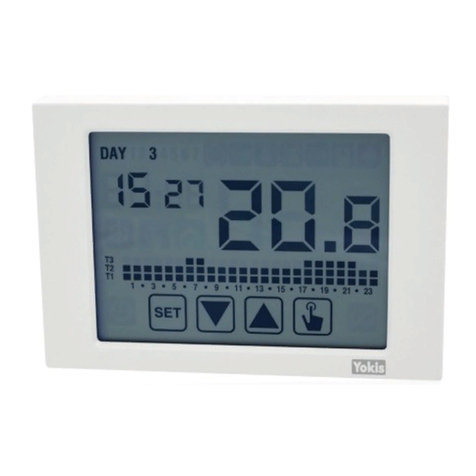
Yokis Thermarp Quick guide

DIGITAL THERMOSTAT WITH DIRECT OR WIRELESS CONNECTION
INSTALLATION, PROGRAMMING AND USE INSTRUCTION MANUAL
THERMARP
Cod. 5454489

DS1054-057 P2
INDEX
1. GENERAL DESCRIPTION...................................................................................................................................4
1.1. MAIN FEATURES.........................................................................................................................................4
1.2. DIMENSIONS ..............................................................................................................................................4
1.3. DESCRIPTION OF TERMINALS ..................................................................................................................4
1.4. DESCRIPTION OF COMPONENTS ............................................................................................................5
2. AUTOMATIC OPERATION.................................................................................................................................6
3. MANUAL OPERATION ......................................................................................................................................6
4. SWITCH FROM AUTOMATIC TO MANUAL OPERATION AND VICE VERSA .................................................7
5. OFF OPERATION...............................................................................................................................................8
6. MINIMUM AND MAXIMUM VALUES ................................................................................................................8
7. CONFIGURATION MODE .................................................................................................................................9
7.1. TIME AND DATE ................................................................................................................................10
7.1.1. Changing the daylight saving time settings ...................................................................................10
7.2. EDIT PROGRAMS ................................................................................................................................11
7.3. CHANGE TEMPERATURES (T1), T2, T3 ..............................................................................................12
7.4. SETTING A TIMER ...............................................................................................................................13
7.4.1. Manual timed ..................................................................................................................................13
7.4.2. Automatic timed .............................................................................................................................13
7.4.3. Off timed.........................................................................................................................................13
7.5. ADVANCED CONFIGURATION MENU ..............................................................................................14
7.5.1. Operating mode..............................................................................................................................16
7.5.2. Adjustment mode type for heating ................................................................................................16
7.5.3. Adjustment parameters ..................................................................................................................16
7.5.3.1. On/off adjustment ................................................................................................................17
7.5.3.2. Proportional adjustment TPI (1) (warm-up only) ..................................................................17
7.5.3.3. Emergency control (winter operation only)..........................................................................18
7.5.4. Antifreeze temperature ..................................................................................................................19
7.5.5. Auxiliary input management ...........................................................................................................19
7.5.6. Keypad locking password ...............................................................................................................19
7.5.7. Hours of system operation .............................................................................................................19
7.5.8. View SW version..............................................................................................................................20
7.5.9. View HW version .............................................................................................................................20
7.6. RADIO-FREQUENCY MENU ...............................................................................................................20
7.6.1. RF Test.............................................................................................................................................22
7.6.2. Configuration reception from AppPRO..........................................................................................22
7.6.3. Rec E5 : Connection to one MRT module.......................................................................................22
7.6.4. Ap E7 : Access point definition.......................................................................................................23
7.6.5. Def 24 : Erase access points ...........................................................................................................23
7.6.6. Def 25 : Thermostat wireless configuration reset ..........................................................................23
8. REMOTE SWITCH-OFF ....................................................................................................................................24
9. THERMOSTAT RESET ......................................................................................................................................24
10. INSTALLATION ................................................................................................................................................24
10.1. SAFETY WARNING .................................................................................................................................24
10.2. HOW TO START THE THERMOSTAT.....................................................................................................24
10.3. CONNECTIONS ......................................................................................................................................28
10.4. CONFIGURATIONS.................................................................................................................................29
10.4.1. Single-zone thermostat configuration with direct wiring.............................................................29
10.4.2. Single-zone thermostat configuration with wireless connection (via MTR) and check ................29
10.4.3. How to extend the range..............................................................................................................30

P3
DS1054-057
10.4.4. YOKIS PRO: Single-zone thermostat configuration with direct wiring ........................................31
10.4.5. YOKIS PRO: Single-zone thermostat configuration with wireless connection (MTR) ..................32
10.4.6. Configuration of multiple thermostats, one in each zone, in a multi-zone system......................33
11. REPLACING THE BATTERIES ..........................................................................................................................36
12. TECHNICAL SPECIFICATIONS........................................................................................................................36
13. DEFAULT SETTINGS ........................................................................................................................................36
14. DEFAULT WINTER PROGRAMS ......................................................................................................................37
15. DEFAULT SUMMER PROGRAMS.....................................................................................................................37

DS1054-057 P4
1. GENERAL DESCRIPTION
Thermarp is a weekly electronic touchscreen thermostat designed to control the room temperature in heating
and cooling mode. The device can control a Yokis receiver by means of signals and radio-frequency.
Thermarp is powered by two AAA batteries and no wiring is required. This means that the thermostat can be
installed in any position inside the room without any masonry work. The large backlit touchscreen display provide
a clear view even in the dark.
1.1. MAIN FEATURES
Summer and winter operating modes.
Model available in white.
1.5V AAA type battery power supply.
Seven programs available for heating or cooling operation.
Capacitive touchscreen display (finger-touch sensitive).
Installation on wall or in 503 box.
Weekly programming with three adjustable temperature levels.
1.2. DIMENSIONS
125 mm
mm58
26 mm
10.5 mm 15.5 mm
1.3. DESCRIPTION OF TERMINALS
M1 terminal board
]
AUX Auxiliary inputs used for connecting to an external temperature sensor or for connection to a
telephone dialler.
M2 terminal board
NA Normally open relay output contact
NC Normally closed relay output contact
CCommon relay contact
•
•
•
•
•
•
•

P5DS1054-057
1.4. DESCRIPTION OF COMPONENTS
2
3
4
5
6
7
8
9
Day of the week (DAY 1 = Monday)
Configuration menu:
: set date/time and daylight saving time
: edit program (for automatic operation)
: set temperatures T1, T2, T3
: timer menu
: advanced configuration menu
: not used
: radio-frequency transmission menu
3. Measured ambient temperature
4. Low battery indication
5. Keypad (only active if the device is attached to the wall base)
6. Off operation
7. Chart of the active program for the current day (in automatic operation)
8. Indicators:
: Active load in summer/cooling mode
: Manual operation active
: Active load in winter/heating mode
Hours and minutes
The functions on the keypad vary according to the status of the device. There are no multi-function buttons, i.e.
situations which require the simultaneous pressing of two or more buttons.
There are two types of touches:
- short touch
- long touch, press lasting more than 3 seconds
When a button is pressed, the display is blue.
IMPORTANT: Press the buttons with your fingers. Do not use sharp objects.
IMPORTANT: The keypad is not active until the device is properly attached to the wall base.
1.
2.
9.

DS1054-057 P6
2. AUTOMATIC OPERATION
In automatic operation, the thermostat adjusts the temperature using T1, T2 or T3 as setpoint according to the
day and time.
The lower part of the display shows the temperature values used in each time slot for the current day.
In the following example, the day 3 (Wednesday) 8:35 Tm is set to = T2.
The daily programs for automatic operation and the values of the three reference temperatures (T1, T2 and T3)
can be set in the Configuration menu.
3. MANUAL OPERATION
In manual operation, the thermostat behaves like a normal thermostat, adjusting according to the Tm (manual
setpoint) temperature, regardless of the day and time.
Manual operation is indicated by the symbol which lights up.
To change the setpoint (Tm), press the button to turn on the display, then press again.
1. The currently setpoint (Tm) starts flashing.
2. Set the desired setpoint with button and and confirm by pressing button .
3. The room temperature will appear again at this point.
Manual setpoint
setting
(Tm)
Manual
operation

P7DS1054-057
4. SWITCH FROM AUTOMATIC TO MANUAL OPERATION AND
VICE VERSA
To switch from automatic to manual operation:
Press the button twice. The previously set manual operation setpoint (Tm) will start flashing.
Confirm the Tm setpoint or change it, if required, using buttons and . Press to confirm the
selection.
At this point, the room temperature value reappears and the thermostat operates in manual mode.
To switch between manual and automatic operation, hold button pressed for about three seconds.
3s
Automatic
operation
Manual setpoint
(Tm) setting
Manual
operation
Manual setpoint (Tm) setting
Manual operation
1.
2.
3.

DS1054-057 P8
5. OFF OPERATION
In off mode, the thermostat does not make any adjustment but continues to display the day, time and the
measured temperature.
Note: In case of heating/winter operation, the thermostat maintains a minimum “Toff antifreeze temperature” in
order to avoid freezing in the system or in the rooms in which the thermostat is installed.
The “Toff” parameter can be set to values from 1°C to 50°C or be excluded entirely. In the latter case, no
minimum temperature is guaranteed.
By default, the parameter is set to 6°C but this value can be changed by accessing the Advanced
Configurations (ADV) menu (see “Antifreeze temperature”).
Hold button pressed until the symbol appears on the display.
To reactivate the adjustment, hold button pressed for about three seconds.
MANUAL OR
AUTOMATIC
OPERATION
3s
3s
6. MINIMUM AND MAXIMUM VALUES
In any operating mode (automatic / manual / off), it is always possible to display the minimum and maximum
temperature values measured by the temperature sensor in use.
To display these values, press button (maximum value Hi) or (minimum value L0).
While this is displayed, it is possible to reset one of the two values by holding button pressed until the current
temperature value appears.
Press button also to check whether the thermostat is displaying its own internal temperature sensor (default)
or an external temperature sensor (*).
(*) In this case, it is a temperature sensor connected to the AUX terminals, appropriately configured in the Advanced
Configurations menu (see chapter 7.5).

P9DS1054-057
The following operating parameters can be configured in the
configuration menu:
Time and date
Automatic operation: programming
Automatic operation: temperatures T1/T2/T3
Timer
Advanced configurations (see Parag. 7.5)
Radio-frequency menu
Hold button pressed for longer than 3 seconds to open configuration
mode.
The following block chart summarises:
CONFIGURABLE PARAMETERS
•
•
•
•
•
•
7. CONFIGURATION MODE
R
Advanced
congurations
adio
See
Timer
(T1) T2T3
Programs
Time and
date
7.1
3S
7.1.1
3S
3S
3S
3S
3S
3S
3S
Automatic /
manual / O
operation
7.2
7.3
7.5
7.6
7.4
Daylight saving
time settings

DS1054-057 P10
7.1. TIME AND DATE
Proceed as follows to change the set time and date:
On the operating screen, hold button pressed for three seconds. The icon will start flashing on the
display.
Press button to access the parameter configuration. The icon will stop flashing.
The seconds field will start flashing.
Use buttons and to change the values. Press button to confirm and move on to the next
parameter.
The parameter sequence to be entered is: seconds* -> minutes -> hours -> year -> month -> day.
(*) For seconds, only resetting to 00 is possible by pressing the buttons and .
Once all the parameters have been set, to exit and return to the configuration menu, briefly press the button
. The icon will start flashing again. To exit and return to normal operation (automatic, manual), hold
button pressed or wait for the timeout (approx. 40 seconds).
Note: this menu can also be used to change the parameters for the standard/daylight saving time switch, as
described below.
7.1.1. Changing the daylight saving time settings
By default, the thermostat is configured to switch to daylight saving time on the last Sunday in March at 02:00
a.m. and to switch back to standard time on the last Sunday in October at 03:00 a.m. as customary in Europe.
Therefore, no changes are normally necessary.
It is however possible, in the case of particular installations, to disable the automatic time switch or to change the
date or time of the time switch.
Proceed as follows in this case:
1.
2.
4.
5.
When changing any of the parameters (seconds, minutes,
hour, year, month or day), hold button pressed until
“Aut0” appears on the display.
Use buttons and to choose whether to keep the
automatic time change (Aut0 0n) or deactivate it (Aut0
0FF) and confirm with button .
Setting 0FF will go back to time/date change. By setting
0n the daylight saving time switch setting (marked by the
symbol ) is displayed. In the example:
a. Sunday (7) of the last week (LA) of March (03) at 2 a.m.
(02)
b.If necessary, change the parameters using buttons
and , move on to the next parameter using the
button . The sequence requires entering:
i. day (1...7) of the week
ii. week of the month (first, second, third,
fourth, last - LA)
iii. month (1…12)
iv. time
1.
2.
3.
3s
If OFF
If ON
NEXT PAGE

P11DS1054-057
Press the button to display the PREVIOUS PAGE
setting current for switching to the standard time
(marked by symbol ). In the example:
a. Sunday (7) of the last week (LA) of October (10) at
3 a.m. (03)
b.If necessary, change the parameters using buttons
and and go to the next parameter with button
.
The sequence includes the entering:
i. day (1...7) of the week
ii. week of the month (first, second, third,
fourth, last - LA)
iii. month (1...12)
iv. time
Once all the parameters have been set, press button
to exit and return to the configuration menu.
To exit and return to normal operation, hold button
pressed or wait for the timeout (approx. 40 seconds).
4.
5.
6.
7.2. EDIT PROGRAMS
This menu can be used to modify the automatic operation programs. The thermostat is configured to run program
P1 from Monday to Friday and P2 on Saturday and Sunday (program profiles can be found at the bottom of the
booklet).
You can change this configuration if it does not meet your needs. In particular, for every day of the week, you
can:
choose a specific profile among the seven available ones;
customise in detail the chosen profile.
Proceed as follows:
•
•
On the operating screen, hold button pressed for
three seconds. The icon will start flashing on the
display.
Briefly press button until the symbol flashes.
Press button to access parameter editing. The icon
will stop flashing.
The program page shows on the first day of the week
(DAY 1) flashing, the current program (e.g. P1 with its
operating mode or ) and the profile corresponding
to the program.
Press button or to select the day of the week for
which you want to change the program. Press button
to edit the program.
The program indication icon starts flashing. Press button
or to select one of the seven available programs.
Press the button to confirm and return to the previous
screen (day selection).
1.
2.
3.
4.
5.
PREVIOUS PAGE

DS1054-057 P12
If no program exactly meets your needs, choose the
program that comes closest and press a second time
to access the program profile edit.
The time indicator shows 00:00, the temperature level
icon (T1, T2 or T3) and the vertical bar corresponding
to the time flash. Press button or to change the
temperature level and button to move on to the next
hour. Set the desired temperature level for each hour of
the day.
For each hour, it is also possible to delay the start of
adjustment by 15’, 30’ or 45’ minutes. After setting the
temperature as described above, press and hold the
button for 3 seconds to set a delay. The minute
indicator will start flashing. Using button or set
the delay time and press button to confirm and move
to the time hour.
6.
7.
8.
When the program has been edited as required, go back to the day selection page by pressing button
twice and repeat, if necessary, the operations described above for the other days of the week. When all the
changes have been made, exit the configuration menu by holding the button pressed.
7.3. CHANGE TEMPERATURES (T1), T2, T3
This menu can be used to change the three automatic operation temperatures.
Proceed as follows to edit the program:
On the operating screen, hold button pressed for three seconds. The icon will start flashing on the
display.
Briefly press button until the symbol flashes. Press button to access the parameter editing function.
The icon will stop flashing.
Once all the parameters have been set, press the button to exit and return to the programming menu.
The icon will stop flashing. To exit and go back to normal operation, hold pressed or wait for the
timeout (approx. 40 seconds).
(*)IMPORTANT!:
T1 cannot be configured in cooling mode.
The set temperature values must comply with the condition: (T1)* ≤ T2 ≤ T3.
9.
1.
2.
6.
The T1 temperature value will flash. Change the value using
buttons and and press the button to confirm and
go to editing T2.
Change the value using buttons and and press the
button to confirm and go to editing T3.
Change the value using buttons and and press the
button to go back to the T1 temperature editing page.
3.
4.
5.

P13DS1054-057
7.4. SETTING A TIMER
The timer makes it possible to maintain the current operation (manual, automatic and off) for a certain period
(hours or days), after which the thermostat changes its operating mode, as described below. The timed operations
are:
7.4.1. Manual timed
If a timer is set to manual state, manual state is maintained until the end of the timer after which the system
switches to automatic operation.
7.4.2. Automatic timed
If a timer is set in the automatic state, automatic state is maintained until the end of the timer after which the
system it switches to off operation.
7.4.3. Off timed
If a timer is set to the off state, off state is maintained until the end of the timer after which the system switches
to the operation it had before switching off (automatic or manual).
If a timer is set, the following symbol appears on the display
IMPORTANT: The timer is calculated in minutes and, therefore, if for example you set a 3-day timing at 12:15 on
Tuesday it will expire at 12:15 on Friday.
IMPORTANT: The timers may end before their scheduled time if one of the following actions occurs:
change of time/date (including change of daylight saving time);
manual change of operating mode;
digital input switching;
change of operating logic from winter to summer (or vice versa).
•
•
•
•

DS1054-057 P14
Proceed as follows to set a timer from current operation:
On the operating screen, hold button pressed for three seconds. The icon will start flashing on the
display.
Briefly press button until the symbol flashes. Press button to access the parameter editing
function.
3. The icon indicating the timer value starts flashing (00 no
timing). Enter the timer value (1 to 99) with buttons
or , press button to confirm.
The icon indicating the unit value (h0ur or day) starts
flashing. Use buttons and to choose whether the
timer is in (h0ur) or days (day).
4.
Once all the parameters have been set, press button to exit and go back to the programming menu. To
exit and go back to normal operation, hold button pressed or wait for the timeout (approx. 40 seconds).
7.5. ADVANCED CONFIGURATION MENU
Using the advanced configuration menu (ADV), it is possible to modify or display the following operating
parameters:
Operating mode (heating or cooling)
Control type (on-off or proportional)
Parameters relating to adjustment type
Antifreeze temperature
Auxiliary input configuration
Password for keyboard lock
Operation hours
Software version
Hardware version
To access the ADV menu:
On the operating screen, hold button pressed for three seconds. The icon will start flashing on the
display.
Briefly press button until the symbol flashes. Press button to access the parameter editing
function.
The first parameter in the menu starts flashing. Use buttons and to change the parameter and button
to confirm and go to the next parameter. Press to exit the parameter editing function.
1.
2.
5.
•
•
•
•
•
•
•
•
•
1.
2.
3.

P15DS1054-057
The following block chart summarises:
CONFIGURABLE ADVANCED PARAMETERS
Summer/Winter
Antifreeze temp.
Auxiliary
input
Keypad
password
Time function
System
SW version
HW version
7.5.1
7.5.4
7.5.5
7.5.6
7.5.7
7.5.8
7.5.9
7.5
Band
Period
7.5.2
7.5.3
Prop.
Winter
Summer
Dierential Dierential
On / O or
Proportional mode

DS1054-057 P16
7.5.1. Operating mode
This parameter can be used to specify the operating mode of the thermostat between winter/heating and
summer/cooling .
7.5.2. Adjustment mode type for heating
For the heating operation mode, you can choose between on/off control (rEG 0) or proportional control
(rEg P).
7.5.3. Adjustment parameters
In the case of on/off adjustment (rEG 0), the only parameter to be set is the differential (dIF), which can assume
values between 0.1°C and 1°C (parameter to be set also for cooling mode).
In the case of proportional control (rEg P), the parameters to be set are the control band (bnd) and the control
period (PEr).
Note: The presettings are suitable for most situations. Change these settings only when actually needed.
The difference between the two types of adjustment is summarised here.

P17DS1054-057
7.5.3.1. On/off adjustment
In on/off mode, the thermostat measures the room temperature once a minute and controls the system according
to the following logic:
ON relay
SET-dIF SET
OFF relay
Temperature
up
ON relay
(SET+dIF)SET
OFF relay
Temperature
up
heating mode cooling mode
SET is the setpoint and dIF is the differential or hysteresis (this is useful to avoid continuous switching on and off
which could be detrimental to the system when the setpoint is reached).
7.5.3.2. Proportional adjustment TPI (1) (warm-up only)
In heating mode, proportional control is also available in addition to on/off control to allow more precise control
in order to obtain a constant temperature.
This setting requires you to specify two parameters:
the band, which develops symmetrically to the right and left of the setpoint. It can assume values between
0.5°C and 5°C. Outside these values, the heating will always be on (if room temperature < (setpoint - band)
or always off (if room temperature > setpoint + band);
the control period which is the duration of the control cycle (on time + heating off time) and can take values
of 10, 20 or 30 minutes.
During operation, at the beginning of the control period, the thermostat measures the room temperature (TA)
and compares it with the setpoint. According to the difference, the switch-on time (and consequently also the
switch-off time) within the next control period is calculated. The closer the measured temperature is to the
setpoint - band value, the more the on time will be predominant over the off time. Conversely, the closer the
measured temperature is to the setpoint + band value, the more the off time will be predominant than the on
time (2).
increasing
time
% Relay ON
100%
0%
50%
SET-
BAND
SET SET+
BAND
TA
After the control time (10, 20 or 30 minutes), the thermostat compares the room temperature with the setpoint
again and updates the on/off times for the new period.
The proportional control performance is subject to the correct choice of parameters.
Select the setting band value as follows:
broad band (5°C) for systems with high thermal gradient (3);
narrow band (0.5°C) for systems with low thermal gradient (3).
Select the value of the setting period as follows:
10’ for low thermal inertia systems (fan-coil)
20’ for medium thermal inertia systems (aluminium radiators)
30’ for high thermal inertia systems (cast iron radiators)
•
•
•
•
•
•
•

DS1054-057 P18
IMPORTANT: The thermostat is configured by default to operate in on/off mode with differential set at 0.3°C.
(1)Thermarp when used with TPI adjustment mode complies with Control Class IV of the ErP/Energy related
Products Directive of 26/09/2015.
Time Proportional & Integral (TPI) control reduces the average temperature of the heating water, improves
ambient temperature control accuracy and increases the overall system efficiency.
The ErP Directive estimates that TPI control allows a seasonal energy saving of 2%.
(2) Example: with SET= 19°C BAND=1°C and TA=19.3°C, the on % is equal to 35%. If the set period is 20 minutes,
we will have an on time of 7 minutes, followed by an off time of 13 minutes.
(3)The ambient temperature gradient is the temperature variation curve between floor and ceiling. Floor systems
generate a minimum thermal gradient, close to the optimum, with very similar floor and ceiling temperatures.
Radiator systems and especially connector systems generate a higher gradient curve, in which the ceiling
temperature is higher than the floor temperature.
Vertical thermal gradient with different types of heating elements
ideal conditions
panel systems
radiator systems
fan coil systems
Temperature (°C)
Height (m)
7.5.3.3. Emergency control (winter operation only)
The thermostat makes an emergency adjustment if an error occurs during the reading of the sensor or if the time
is lost.
In case of sensor error, if the antifreeze function is not excluded, the thermostat activates the load for 10 minutes
every 4 hours. The display shows “Err” in field (7).
In the event of a loss of time (due to battery discharge or blackout lasting longer than the power reserve), the
thermostat restarts from off operation, adjusting according to the antifreeze temperature, if it has not been
previously deactivated. Reset the date/time to return to normal operation (program changes and settings are
retained in memory).

P19DS1054-057
7.5.4. Antifreeze temperature
In heating mode, it is possible to set a safety temperature
(antifreeze temperature - Off) to be maintained even if
the thermostat is turned off. It is possible to choose a
value between 1°C and 50°C. It is also possible to disable
the antifreeze function by holding down the button
until “_ _._” appears on the display. In this case, if the
thermostat is switched off, no safety temperature is
maintained.
7.5.5. Auxiliary input management
The thermostat has a configurable input to connect an
external temperature sensor or a voltage-free contact in
case you want to connect a telephone dialler to turn the
thermostat on or off remotely.
The word “ESt” appears. Select:
- “---” if nothing is connected to the input.
- “dIG” if you want to hook up a dialler.
- if you want to connect an external temperature
sensor.
7.5.6. Keypad locking password
It is possible to set a keyboard which is useful if the
thermostat is installed in public places or if you want
to prevent anyone from changing the operating
parameters.
To set a password, enter a value between 001 and 999
in the “PAs” field. To deactivate the password, hold
pressed the key until “_ _._” appears.
When the keypad is locked, the thermostat performs all its functions using the set control parameters.
If the keypad lock is active and a button is pressed, the display shows “bL0c” with and the dashes will flash for a
few seconds. Enter the password to unlock the keypad, which will remain unlocked for 30 second from the last
touch.
7.5.7. Hours of system operation
This page shows the total number of hours of operation
of the system (relay ON) in the operating mode (identified
by icons or ).
It is a four-digit counter which can be reset by holding
down the button until 0000 appears.

DS1054-057 P20
7.5.8. View SW version
This screen shows the software version of the thermostat.
7.5.9. View HW version
This page shows the hardware version of the thermostat.
Once all the parameters have been set, press button to exit and return to the configuration menu. To exit and
go back to normal operation, hold button pressed or wait for the timeout (approx. 40 seconds).
7.6. RADIO-FREQUENCY MENU
The “RF menu” item provides access to all the wireless settings of the thermostat:
Connected MTR wireless actuator connection test.
Configuration reception from AppPRO (as Control Point).
Wire connection to an MTR actuator set-up.
Radio Bus Access Point connection set-up.
Erase access points.
Erase all wireless settings.
Proceed as follows to access the RF menu:
On the operating screen, hold button pressed for three seconds. The icon will start flashing on the
display.
Press button briefly until the symbol flashes then press the button .
•
•
•
•
•
•
1.
2.
Other manuals for Thermarp
1
This manual suits for next models
1
Table of contents
Other Yokis Thermostat manuals