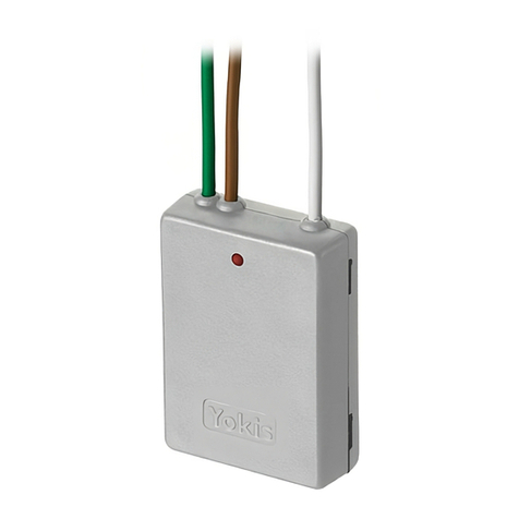
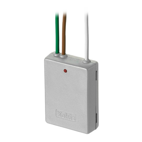
Yokis E2BP User manual


GB
5454402 2-channel flush-mounted transmitter
All YOKIS transmitters are compatible with
YOKIS receivers
(Relays, Dimmer and Shutter Modules).
RADIO RANGE:
Standard range:
•In the same room (< 100 m²)
•50m in open range
(Range may be reduced by presence of metallic
elements, crossing of walls or partitions)
Power range (*):
•Inside 100m² apartments with perpendicular
crossing of main wall or ceiling
•250m in open range
(Range may be reduced by presence of metallic
elements, crossing of walls or partitions)
RADIO TRANSMISSION:
The transmitter LED lights up only if radio
transmission was successful.
Adding an intermediate receiver will allow to solve a
problem of insufficient range (see § “How to increase
the range”).
The E2BP/E2BPP may be wired behind pushbuttons (or switches) of any model. Wiring
both channels is not indispensable: a single pushbutton can be used connected to a single
channel.
Switches can be used instead of pushbuttons to drive MTR2000ER receivers. In this
case, switch 5 times rapidly (not 10!) instead of using the 5 press sequence. Repeat the
connection procedure by pressing 5 times to use a pushbutton again instead of the switch.
D I R E C T M O D E
Press the pushbutton to be connected on the
transmitter (E) 5 times**.
The transmitter LED will start flashing for 30
seconds, indicating that the system is waiting
for connection.
** Each press must last less than 0.7 seconds
Briefly press the pushbutton in the ‘connect’hole
of the receiver (R) (on the front or the back of the
receiver) with the point of a pencil while the
transmitter LED is flashing.
The transmitter LED will stop flashing.
Warning: the receiver must be powered.
DIRECT MODE CENTRALISATION
A command can be centralised by repeating the same procedure on up to four receivers. In case that more
than 4 receivers should be driven, use the Radio Bus.
(*) Contact an Urmet retailer or go to www.yokis.com/ for information on availability.
P8
E2BP
E2BPX
TLC2C
TLC8C
GALET8T
TLM1T45
TLM2T45
TLM4T45
2
-
channel
flush
-
mounted
transmitter
with
external
aerial
5454408
5454401
2
-
pushbutton
remote
control
5454403 8-pushbutton remote control
5454405 8 pushbutton flat remote control
5454411 1-pushbutton wall-mounted remote
control
5454406 2-pushbutton wall-mounted remote
control
5454412 4-pushbutton wall-mounted remote control
2
-
channel
flush
-
mounted
POWER
t
ransmitter
POWER with external aerial
NEW POWER RANGE (soon available *)
E2BPP
5454413 2-channel flush-mounted POWER transmitter
TLC2CP
5454415 2-pushbutton POWER remote control
TLC8CP
5454423 8-pushbutton POWER remote control
GALET8TP
5454424 8 pushbutton flat POWER remote control
E2BPP
X
5454414
control
1
-
pushbutton
wall
-
mounted
POWER
remote
TLM1T45P
5454417
TLM2T45P
5454419
TLM4T45P
5454421
4
-
pushbutton
wall
-
mounted
POWER
remote
control
2
-
pushbutton
wall
-
mounted
POWER
remote
control
T
echnical
sp
ecifications:
- CR2032 Lithium battery (included)
- Battery life > 7 years
- Max. 4 receivers per transmitter button
- Operating temperature: from -10 to +
50°C
- IP54 protection
- Max. relative humidity 80%
- Frequency: 2,4 GHz
- Transmission: two-way
1
2
Simply
repeat
the
same
procedure
to
delete
a
connection
The LED will light up on transmitters
only
if
radio
transmission
was
successful
DS1054
-
009A
RADIO TRANSMITTERS

R A D I O B U S M O D E
An unlimited number of receivers may be connected together to form a radio bus. This makes it possible to:
•
send controls to groups of receivers on the radio bus (see “Radio Memo”)
•
send a control from a transmitter to a receiver which is out of direct range
•
centralise operation of all lights or all window shutters
All receivers (MTR2000ER - MTV500ER - MVR500ER) are compatible with the radio bus.
The window shutter controls may also be sent via lighting modules and vice versa.
See the “Radio Memo”or go to www.yokis.com for more information on the radio bus.
HOW TO CREATE A RADIO BUS BETWEEN RECEIVERS
Press “Connect”on receiver 1. Its LED will start flashing
.
While the LED is flashing, press “Connect”on receiver 2
.
To confirm the connection, the LED of receiver 2 will flash once and the LED of receiver 1 will stop flashing. The relays of the
two receivers will switch once when the connection has been established.
Unlimited number
Possible with of receivers on
all Yokis receivers the radio bus
Le d
Le d
Le d
Led
C o nn e ct
R1
R1
C on ne c t
R1
R1
C on ne c t
R1
R1
C on ne c t
HOW TO INCREASE THE RANGE USING AN INTERMEDIATE RECEIVER
Led
Led
Connect
Connect
1
. Define a radio bus between receivers as described above.
2
. Connect the transmitter to the receiver to be controlled by pressing the chosen pushbutton on the transmitter (E) 5 times.
Press the pushbutton in the “Connect”hole of the receiver (R) while the transmitter LED is flashing.
3
. At this point, create an access point on the receiver nearest to the transmitter by pressing the transmitter (E) pushbutton
7 times (the same one programmed in the previous step). The transmitter LED will start flashing rapidly. Then press the
pushbutton in the “Connect”hole of the first receiver (R) once (1
press)
. The transmitter and receiver LED will stop flash-
ing.
RADIO BUS CENTRALISATION
The following five steps are needed for centralisation:
1
. Create the radio bus between receivers
Follow the procedure described above.
2
. Connect the pushbutton of the transmitter to the nearest receiver
(it is advisable to connect the transmitter to the nearest receiver to avoid problems of range)
1
. Press the chosen pushbutton on the transmitter 5
times.
2
. Press the pushbutton in the ‘Connect’hole of the receiver with the point of a pencil while the transmitter LED is flash-
ing.
3
. The receiver will switch the relay briefly and the transmitter LED will go out.
P9
R1
E7
R1 R1
E5
DS1054
-
009A

3
. How to set the pushbutton as centralised
1
. Press the transmitter pushbutton 10 times (Configuration Menu). The transmitter LED will flash rapidly.
2
. Press the chosen pushbutton 6 times while the LED is flashing.
3
. At the end of the press sequence, the LED will flash 6 times to confirm the configuration.
4
. How to set centralisation to operate lights (default) or window shutters
The centralised pushbutton will operate the light modules by default (MTR2000ER and MTV500ER). Skip this step.
If you want the centralised control to operate the MVR500ER window shutter modules:
1
. Press any pushbutton on the transmitter 10 times (Configuration Menu). The transmitter LED will flash rapidly.
2
. Press the chosen pushbutton 11 times while the LED is flashing.
3
. At the end of the press sequence, the LED will flash once (1 press) to confirm the configuration.
5
. How to define pushbutton operating mode
Follow the instructions in the next paragraph to establish the effect of the centralised pushbutton on the lights or window
shutter modules.
P U S H B U T T O N O P E R AT I N G M O D E
* Default configuration
To change the operating mode of a pushbutton:
1 - Press any pushbutton on the transmitter 10 times (Configuration Menu).
The transmitter LED will flash rapidly.
2 - While the LED is flashing, press the chosen button from 1 to 4 times to select the required operating function.
3 - The LED will flash from 1 to 4 times to confirm configuration.
U S E F U L F U N C T I O N S
How to copy a pushbutton onto another pushbutton (between two different transmitters or on the same transmitter).
Only the first of the configured connections will be copied: the new button will be set to operating mode 1 (toggle)
1- Press the new button to be created 5
times
. The LED will start flashing.
2- While the LED is flashing, press the button to copied until the LED flashes.
How to copy a pushbutton (between two different transmitters)
All connections will be copied: the new button will be set to operating mode 1 (toggle)
On the new transmitter:
1- Press any pushbutton on the transmitter 10 times (Configuration Menu). The transmitter LED will flash rapidly.
2- While the LED is flashing, press the destination pushbutton 12
times
. The LED will flash signalling wait state for
approximately 30 seconds.
On the source transmitter:
1- Press any pushbutton on the transmitter 10 times (Configuration Menu). The transmitter LED will flash rapidly.
2- While the LED is flashing, press the pushbutton to be copied 13
times
. The LED will light up during data transfer and then
switch off.
How to duplicate the transmitter completely
On the new transmitter:
1- Press any pushbutton on the transmitter 10 times (Configuration Menu).
The transmitter LED will flash rapidly.
2- Press one of the pushbuttons 14 times while the LED is flashing.
3- The LED will flash at the end of the 14
presses.
On the source transmitter:
1- Press any pushbutton on the transmitter 10 times (Configuration Menu).
The transmitter LED will flash rapidly.
2- Press one of the pushbuttons 14 times while the LED is flashing.
3- The LED will flash at the end of the 14 press sequence.
P10
OPER
A
TING
MODE
MTR2000ER
MTV500ER
MVR500ER
Operating
mode
1*
On
/
Off
Dim
/
Off
Up
/
Stop
/
Down
Operating
mode
2
-
Recall
Memory
Level
Intermediate
position
Operating
mode
3
On
On
Up / Stop
Operating
mode
4
O
f
f
O
f
f
Down / Stop
DS1054
-
009A

How to restore default settings of a transmitter pushbutton
Default setting = clear button connections, go back to mode 1 (toggle), go back to direct mode.
1- Press any pushbutton on the transmitter 10 times (Configuration Menu).
The transmitter LED will flash rapidly.
2- While the LED is flashing, press the button on which to restore default settings 15 times.
3- The LED will flash 5 times at the end of the 15
presses.
How to restore completely default settings of a transmitter
1- Press any pushbutton on the transmitter 10 times (Configuration Menu).
The transmitter LED will flash rapidly.
2- Press one of the pushbuttons 25 times while the LED is flashing.
3- The LED will flash at the end of the 25 presses to confirm that default settings have been restored.
T R A N S M I T T E R C O N F I G U R AT I O N S U M M A R Y TA B L E
Go to the Configuration Menu to configure a transmitter.
To do this, press any transmitter pushbutton or a pushbutton wired to the E2BP/E2BPP 10
times:
the transmitter LED will start flashing rapidly.
Press the pushbutton to be configured the required number of times while the LED is flashing.
Number of presses Possible settings
Pushbutton operating mode
1
On/Off or Up/Stop/Down
2
Memory recall or intermediate position
3
On or Up/Stop
4
Off or Down/Stop
Radio mode
5
Direct mode
6
Radio bus mode
Product on radio bus
10
Lights (default configuration
)
11 Window shutters
12
Prepare to copy to a destination pushbutton
13
Copy a source pushbutton
Copy or clear connections of a pushbutton or of the entire transmitter
14
Completely duplicate the transmitter
15
Restore default settings of a pushbutton
24
Reset access points: delete all radio bus access points
25
Restore transmitter default configuration
Special functions available with MTR2000ER only
16
MTR2000ER contact pulse mode. The receiver generates a 0.5 seconds pulse
17
MTR2000ER contact relay mode. The receiver follows the operation of the transmitter pushbut-
ton
19
MTR2000ER flashing mode: sending of a flash control (0.5 second period for 30 seconds)
For more information on how to create and configure a radio bus using Yokis radio
transmitters and receivers, scan the QR code or go directly to www.yokis.com
WARRANTY:In addition to the warranty required by law, this product is guaranteed for 5 yearsfromdate ofmanufacture. Themate-
rial must be used according tothe instructions provided and for its intended use. Faults must not be caused by deteriorationor acci-
dents resulting from negligence, anomalous useorincorrectinstallation. In all cases, the warranty only includes replacement of faulty
products. No compensation for loss or damage may be claimed
P11
Urmet S.p.a
.
–10154 TORINO (ITALY) –Via Bologna 188/C
For technical inform ation, go to www.yokis.com or call:
Custom er
Service:
+39
011.23.39.810
-
Export
Dept
.
Phone:
+39
011.24.00.250/256
-
Fax:
+39
011.24.00.296
DS1054
-
009A
Other manuals for E2BP
1
This manual suits for next models
31
Table of contents
Other Yokis Transmitter manuals