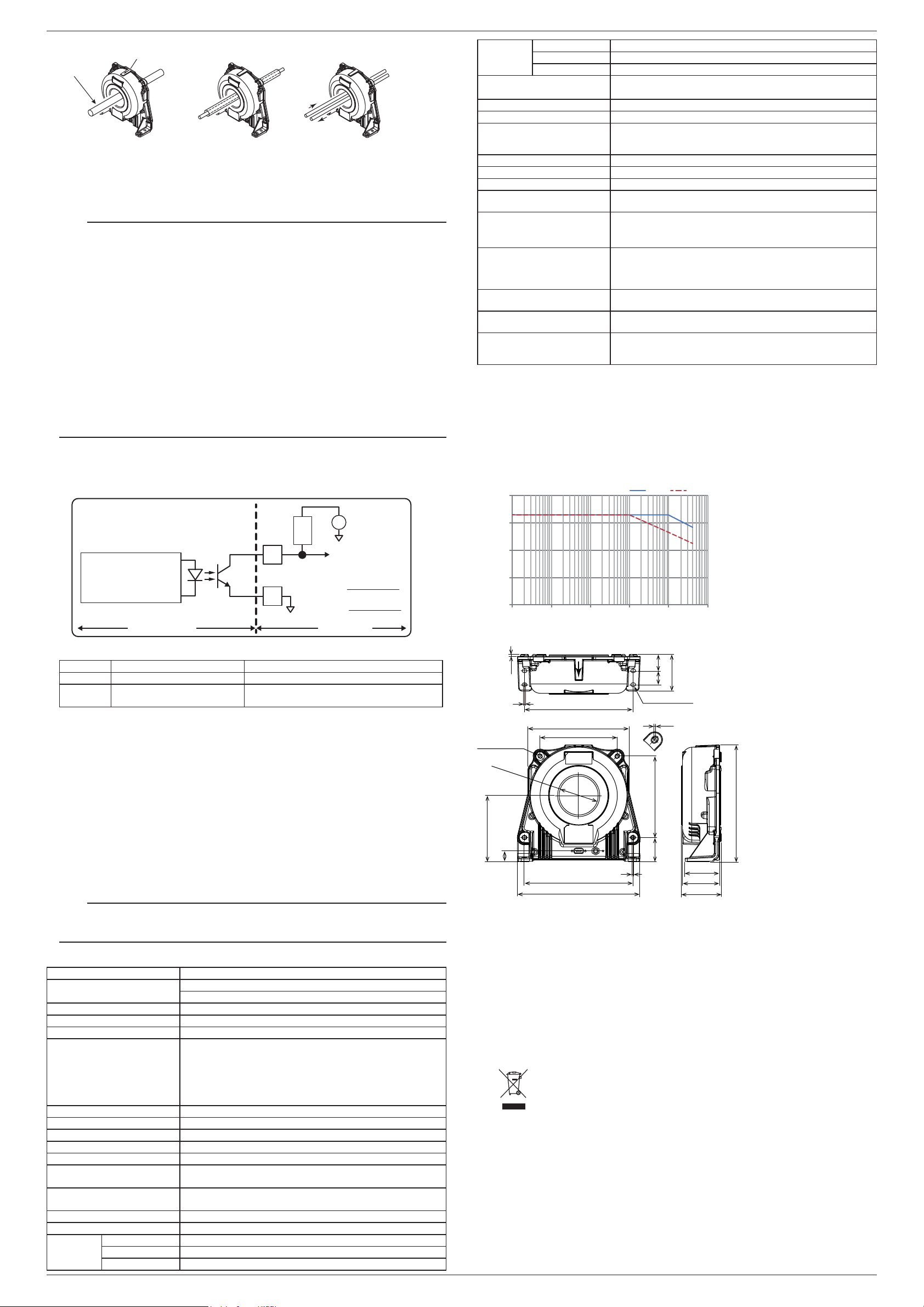
Conductor
Using an magnetic
-shielded conductor
conductors
Current flows in
both directions
Direction of current
Figure 3. Insertion of a Conductor
4.
Check that power is being supplied to the instrument, and then apply the primary current.
5.
Read the measured values. The following calculation is used to determine the current flowing
through the primary conductor.
Example:Whentheoutputcurrentfromtheinstrument'ssecondaryconnector(pin6)is100mA.
CT2000A:100mAx2000=200A
Note
• IftheoperationstatusLEDisoffevenwhenpowerisbeingsuppliedtotheinstrument,the
protection function may be activated. Immediately stop the primary current.
• Onlypassconductorsthroughtheprimaryconductorfeed-throughholeifthecurrentthatyou
want to measure is flowing through the conductors and their current directions are the same.
Correct measurements cannot be taken if you pass conductors with magnetic shielding or
conductorswhosecurrentdirectionsareoppositeofeachotherthroughthefeed-throughhole.
• Makesuretheprimarywiringandsecondarywiringdonotinterferewitheachother.The
secondary wiring may be affected by the primary wiring because it uses a very small current.
Make the secondary wiring as short as possible and maintain its distance from the primary
wiring, without allowing them to be parallel to each other. We recommend AWG24 or higher for
thesecondarywiringmaterial.Twisted-pairmaybebetterthanshieldedcableformeasurement
applications such as inverters.
•The instrument outputs current. Connect the instrument to a measuring instrument with
current input. To connect the instrument to a measuring instrument with voltage input, use an
appropriate shunt resistor to connect the instrument to the voltage input terminals.
•Configure your setup so that the load resistance of the measuring instrument connected to the
secondary signal output is within the specification range.
•Correctmeasurementsmaynotbepossibleinplaceswherethereisanextremelystrong
externalmagneticfieldbesidesthemagneticfieldsproducedbytheprimarycurrentofthe
object to be measured or where there is a strong electric field.
PowerOffIfAbnormalBehaviorOccurs
If you notice smoke or unusual odors coming from the instrument, immediately turn off the
measuring instrument supplying the power. Then, contact your nearest YOKOGAWA dealer.
Status circuit diagram
Active Low Output
Operation status
ICEmax : 30 mA
ICEmin : 2 mA
Collector
DC
Power
Supply
R
3
8
+
-
V+ : 4..+24 V
Rmin(kΩ) =
Rmax(kΩ) =
V+(V) - 0.4 V
30 mA
V+(V) - 0.4 V
2 mA
D-Sub
(9 pin)
Emitter
CT2000A USER SIDE
Photocoupler operation:
ON :
CT2000A is OK
(normal mode)
OFF : CT2000A is not OK
Operation status output
Status Operation Status (8-pin) Output Note
Normal Lessthan0.7V TheLEDturnson.
Overloaded V+ TheLEDturnsoff.Alowfrequencysignalisoutput
as a secondary signal output.
Overload Protection
TheoverloadoccurswhentheprimarycurrentIpexceedsatriplevelsuchthatthefluxgatedetector
becomes completely saturated and, consequently, the current sensor will switch from normal
operation to overload mode.
ThistriplevelisguaranteedtobegreaterthanIpm(3000Apeak)anditsactualvaluedependson
operating conditions such as temperatures and measuring resistance.
Duringtheoverloadmode,thecurrentsensorgeneratesandoutputsalowfrequencysignal.
The measuring operation resumes when the primary current returns in the measuring range
between –Ipn and +Ipn (2000Arms).
Test Winding Connector
The test winding connector is used to test the operation of the current sensor.
When a current is applied between the positive and negative Ip test pins, a current that corresponds
tothetestcurrentwindingnumberof200andcurrenttransformationratioof2000:1isoutputfrom
the secondary signal output pin.
Example: When1AisappliedbetweenthepositiveandnegativeIppins,100mAisoutputfromthe
secondary signal output pin.
Note
To measure the current of the primary conductor that has been passed through the through hole,
donotconnectanythingtothetestwindingIp+orIp-pin.Ifconnected,errorsmaybeinducedin
the sensor output.
5. Specifications
Item Specification
Current Rating DC:0to2000A
AC:3000Apeak
Output Current Primaryratedcurrentat2000Ais1A.
Current Transformation Ratio 2000:1
DirectionofCurrent Per the arrow printed on the main unit.
Accuracy DC:±(0.05%ofreading+30μA)
50/60Hz:±(0.05%ofreading+30μA)sinewave
Standard Conditions
Voltage to earth: 0V
Conductor position: center
Conductor:φ25mm;length,300mmormore;straight
Accuracy warranty period 12months
Effect of Position of Conductor Add±(0.01%ofreading)
MeasurementBand(-3dB) DCto40kHz
Temperature Coefficient Inthe-40to18°C,28to85°Cranges:0.01%/°C
Max.AllowableContinuousInput 3000Apeak
DeratingofMax.AllowableInput Forthemaximumallowablecontinuouscurrentwithrespectto
frequency, see figure 4.
InstantaneousMax.AllowableInput
(0.1sec.orless,referencevalue)
10000Apeak
MaximumRatedVoltage 1000Vrms,CATIII
LoadResistance 0to1Ω(powersupplyvoltage:±14.25V,25°C)
Operating
environment
Temperature -40to85°C
Humidity 20to80%RH(nocondensation)
Altitude 2000 m or less
IMCT2000A-01EN2/2
Storage
environment
Temperature -40to85°C
Humidity 20to80%RH(Nocondensation)
Altitude 2000 m or less
ExternalDimensions Approx.230.5(W)x219.5(H)x75.5(D)mm
(excludingtheconnector,conductorguide,andprotrusions)
DiameterofPrimaryCurrentHole φ70mm
Secondary Connector D-Sub9pin
Test Wiring Connector M8circular3pin
Testcurrent:1Amax.
Number of test windings: 200
Weight Approx.4.2kg.
Power Supply Voltage ±(15V±5%)
MaximumRatedPowerConsumption
Approx.35VA
Current Consumption (at Power
Supply Voltage)
Approx.(225mA+outputcurrent)
Recommended fastening torque
•Flatmounting M6×4steelscrews5.5Nm
M6×4steelscrews5.5Nm
•Straightmounting
Safety standard1Compliant standards
EN61010-11000Vrms
Measurement Category: CAT III2
Pollution degree 23
Emissions Compliant standards
EN61326-1ClassB,EN55011ClassB,Group1
Immunity Compliant standards
EN61326-1Table2(forindustriallocations)
Environmental standard Compliant standards
EN50581Monitoringandcontrolinstrumentsincludingindustrial
monitoring and control instruments.
1 AppliestoproductswithCEmarks.Forinformationonotherproducts,contactyournearestYOKOGAWAdealer.
2 ThisinstrumentismeasurementcategoryIIIproduct.DonotuseitforMeasurementCategoriesIV.
Measurement category O applies to measurement of other circuits that are not directly connected to a main power
supply.
MeasurementcategoryIIappliestoelectricalequipmentthatispoweredthroughafixedinstallation,suchasa
wall outlet wired to a distribution board, and to measurement performed on such wiring.
Measurement category III applies to measurement of facility circuits, such as distribution boards and circuit
breakers.
Measurement category IV applies to measurement of power source circuits, such as entrance cables to buildings
and cable systems, for lowvoltage installations.
3 PollutionDegreeappliestothedegreeofadhesionofasolid,liquid,orgaswhichdeteriorateswithstandvoltageor
surfaceresistivity.Pollutiondegree2appliestonormalindooratmospheres(withonlynon-conductivepollution).
Figure 4. Derating of Primary Current by Frequency
Frequency [Hz]
Maximum Allowable Input Current [Arms]
1
10
100
1000
10000
1 10 100 1000 10000 100000
190.5
145
45.3 153
204
230.5
65
69.5
75.5
219.5
Φ70+1
0
hole
20
1.4
(2)
31
26
68.5
204 4-Φ7x9 hole
(2)
3.5
Figure 5. External Dimensions
Unless otherwise specified, tolerances are ±3% (however, tolerances are ±
0.3 mm when below 10 mm).
Unit: mm
6. Servicing
If you encounter any problems during use, or if the instrument does not appear to be operating
normally, contact your nearest YOKOGAWA dealer.
7. Warranty
Ifyouexperienceabreakdownintheinstrumentduetofaultymanufacturingoraccidentsduring
shipping, contact your nearest YOKOGAWA dealer.
8. Appendix
WasteElectricalandElectronicEquipment(WEEE),Directive
(This directive is valid only in the EU.)
ThisproductcomplieswiththeWEEEDirectivemarkingrequirement.Thismarking
indicates that you must not discard this electrical/electronic product in domestic
household waste.
Product Category
With reference to the equipment types in the WEEE directive, this product is classified
as a “Monitoring and Control instruments” product.
When disposing products in the EU, contact your local Yokogawa Europe B. V. office.
Donotdisposeindomestichouseholdwaste.
Authorized Representative in the EEA
YokogawaEuropeB.V.isAuthorizedRepresentativeofYokogawaTest&MeasurementCorporation
in the EEA for this Product. To contact Yokogawa Europe B. V., see the separate list of worldwide
contacts,PIM113-01Z2.
DisposingoftheInstrument
When disposing of the instrument, follow the laws and ordinances of your country or region.


 User manual")


