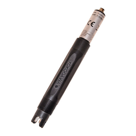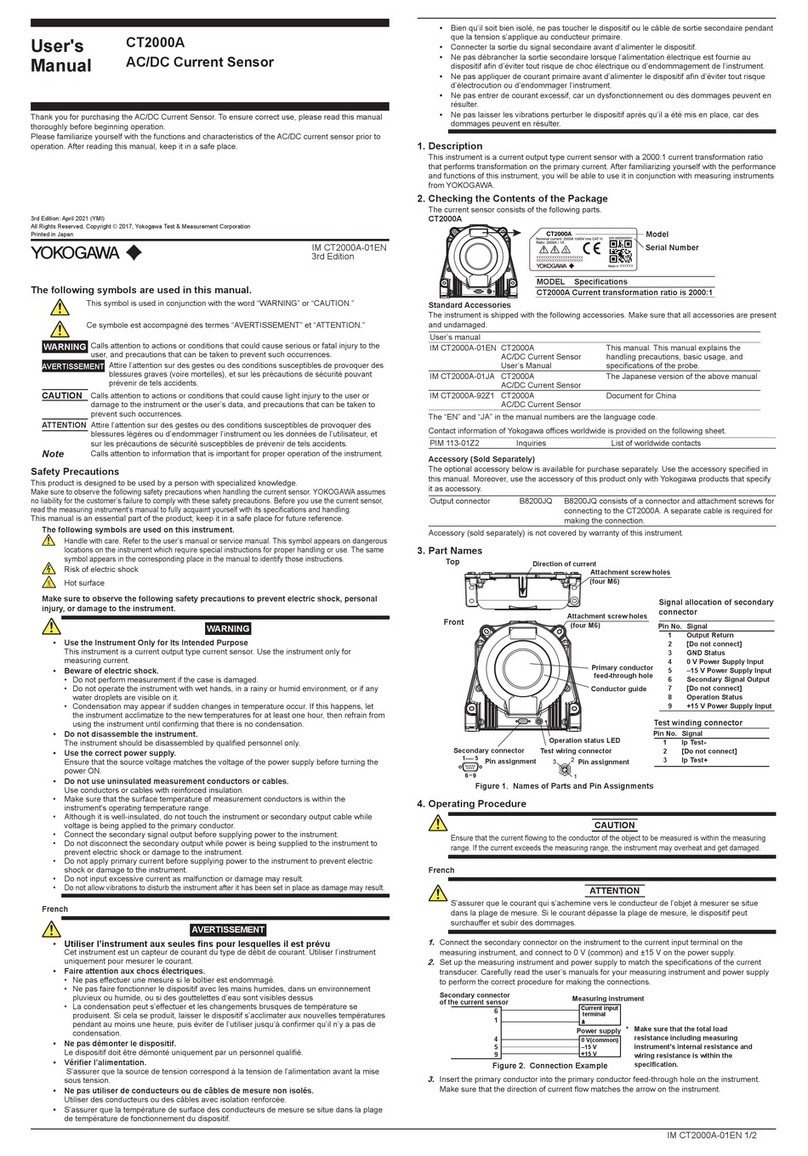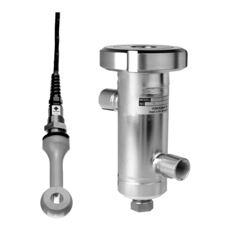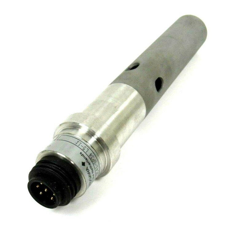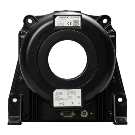
The AC/DC Current Sensors (CT1000, CT200, CT60) are products of Yokogawa Test & Measurement
Corporation. Contact information of Yokogawa offices worldwide is provided on the following sheet.
Document No. Description
PIM 113-01Z2 List of worldwide contacts
Safety Precautions
Make sure to observe the following safety precautions when handling the current sensor. YOKOGAWA assumes
no liability for the customer’s failure to comply with these safety precautions. Before you use the current sensor,
read the measuring instrument’s manual to fully acquaint yourself with its specifications and handling.
The following symbols are used on this instrument.
Warning: handle with care. Refer to the user’s manual or service manual. This symbol
appears on dangerous locations on the instrument which require special instructions for
proper handling or use. The same symbol appears in the corresponding place in the manual
to identify those instructions.
Risk of electric shock
Hot surface
Make sure to observe the following safety precautions to prevent electric shock, personal
injury, or damage to the instrument.
WARNING
• Beware of electric shock.
• Do not perform measurement if the case is damaged.
• Do not operate the device with wet hands, in a rainy or humid environment, or if any
water droplets are visible on it.
• Condensation may appear if sudden changes in temperature occur. If this happens, let
the device acclimatize to the new temperatures for at least one hour, then refrain from
using the device until confirming that there is no condensation.
• Do not disassemble the device.
The device should be disassembled by qualified personnel only.
• Use the correct power supply.
Ensure that the source voltage matches the voltage of the power supply before turning
the power ON.
• Do not use uninsulated measurement conductors or cables.
Use conductors or cables with reinforced insulation.
• Make sure that the surface temperature of measurement conductors is within the
device's operating temperature range.
• Although it is well-insulated, do not touch the device or secondary output cable
while voltage is being applied to the primary conductor.
• Connect the secondary signal output before supplying power to the device.
• Do not disconnect the secondary output while power is being supplied to the device
to prevent electric shock or damage to the instrument.
• Do not apply primary current before supplying power to the device to prevent
electric shock or damage to the instrument.
• Do not input excessive current as malfunction or damage may result.
• Do not allow vibrations to disturb the device after it has been set in place as damage
may result.
The following symbols are used in this manual.
Improper handling or use can lead to injury to the user or damage to the instrument.
This symbol appears on the instrument to indicate that the user must refer to the
user’s manual for special instructions. The same symbol appears in the corresponding
place in the user’s manual to identify those instructions. In the manual, the symbol is
used in conjunction with the word “WARNING” or “CAUTION.”
WARNING Calls attention to actions or conditions that could cause serious or fatal injury to the
user, and precautions that can be taken to prevent such occurrences.
CAUTION Calls attention to actions or conditions that could cause light injury to the user or
damage to the instrument or the user’s data, and precautions that can be taken to
prevent such occurrences.
Note Calls attention to information that is important for proper operation of the instrument.
1. Description
This device is a current output type current sensor with a 1500:1(for CT1000) 1000:1(for CT200)
or 600:1(for CT60) current transformation ratio that performs transformation on the primary current.
After familiarizing yourself with the performance and functions of this device, you will be able to use
it in conjunction with measuring instruments from YOKOGAWA.
2. Configuration
The current sensor consists of the following parts.
Standard parts
1. Current sensor
2. User’s manual
IM CT1000-01EN CT1000, CT200, CT60
AC/DC Current Sensor
User’s Manual
This manual. This manual explains the
handling precautions, basic usage, and
specifications of the probe.
IM CT1000-01JA CT1000、CT200、CT60
AC/DC 電流センサ
The Japanese version of the above manual
The “EN” and “JA” in the manual numbers are the language code.
Contact information of Yokogawa offices worldwide is provided on the following sheet.
PIM 113-01Z2 Inquiries List of worldwide contacts
Thank you for purchasing the AC/DC Current Sensor (Model CT1000,CT200,CT60). To ensure correct
use, please read this manual thoroughly before beginning operation.
Please familiarize yourself with the functions and characteristics of the probe prior
to operation.After reading this manual, keep it in a safe place.
IM CT1000-01EN
9th Edition
IM CT1000-01EN 1/2
Accessories (Sold Separately)
The optional accessories below are available for purchase separately. Use the accessories
specified in this manual. Moreover, use the accessories of this product only with Yokogawa products
that specify them as accessories.
Output connector B8200JQ
Load resistors B8200JR
3. Part Names
Secondary connector
Primary conductor feed-through hole
Conductor guide
CT60CT200
1
5
6
9
CT1000
Front
Top
Front
Top
(two M5)
Attachment screw holes
(two M5)
Attachment screw holes
1 5
6 9
Pin assignment
Figure 1. Names of Parts and Pin Assignments
Primary conductor
feed-through hole
Conductor guide
Secondary connector
Pin assignment
Pin No.
1
2
3
4
5
6
7
8
9
Signal
Output return
[Do not connect]
[Do not connect]
0 V Power Supply Input
–15 V Power Supply Input
Secondary Signal Output
[Do not connect]
[Do not connect]
+15 V Power Supply Input
Signal allocation of secondary
connector
(four M5)
Attachment screw holes
(two M6)
Attachment screw holes
(four M4)
Attachment screw holes
4. Operating Procedure
CAUTION
Ensure that the current flowing to the conductor of the object to be measured is within the measuring
range. If the current exceeds the measuring range, the device may overheat and get damaged.
1.
Connect the secondary connector on the device to the current input terminal on the measuring
instrument, and connect to 0 V (common) and ±15 V on the power supply.
2.
Set up the measuring instrument and power supply to match the specifications of the current
transducer. Carefully read the user’s manuals for your measuring instrument and power supply
to perform the correct procedure for making the connections.
Secondary connector
of the current sensor
4
5
9
6
Power supply
0 V(common)
–15 V
+15 V
Rb Current input
terminal
Measuring instrument
Rb: Load resistor*
Figure 2. Connection Example
* Make sure that the total load resistance
including measuring instrument's internal
resistance and external load resistance (Rb)
is within the specification.
1
3.
Insert the primary conductor into the primary conductor feed-through hole on the device.
Make sure that the direction of current flow matches the arrow on the device. Figure 3 is for the
examples in use with CT200 and CT60. The same idea is applied to CT1000 as well.
Correct
Conductor
Primary current
Incorrect
Using an magnetic
-shielded conductor
Using two parallel
conductors
Current flows in
both directions
Direction of current
Figure 3. Insertion of a Conductor
4.
Check that power is being supplied to the device, and then apply the primary current.
5.
Read the measured values. The following calculation is used to determine the current flowing
through the primary conductor.
Example: When the output current from the device's secondary connector (pin 6) is 100 mA.
CT1000: 100 mA x 1500 = 150 A.
CT200: 100 mA x 1000 = 100 A.
CT60: 100 mA x 600 = 60 A.
Note
• If the NORMAL OPERATION LED is off even when power is being supplied to the device, the
protection function may be activated. Immediately stop the primary current.
• Only pass conductors through the primary conductor feed-through hole if the current that you
want to measure is flowing through the conductors and their current directions are the same.
Correct measurements cannot be taken if you pass conductors with magnetic shielding or
conductors whose current directions are opposite of each other through the feed-through hole.
• Make sure the primary wiring and secondary wiring do not interfere with each other. The
secondary wiring may be affected by the primary wiring because it uses a very small current.
Make the secondary wiring as short as possible and maintain its distance from the primary
wiring, without allowing them to be parallel to each other. We recommend AWG24 or higher for
the secondary wiring material. Twisted-pair may be better than shielded cable for measurement
applications such as inverters.
•The device outputs current. Connect the device to a measuring instrument with current input.
To connect the device to a measuring instrument with voltage input, use an appropriate shunt
resistor to connect the device to the voltage input terminals.
•Configure your setup so that the load resistance of the measuring instrument connected to the
secondary signal output is within the specification range.
•Correct measurements may not be possible in places where there is an extremely strong
external magnetic field besides the magnetic fields produced by the primary current of the
object to be measured or where there is a strong electric field.
CT1000, CT200, CT60
AC/DC Current Sensor
9th Edition: November 2017 (YMI)
All Rights Reserved, Copyright © 2010, Yokogawa Test & Measurement Corporation
Printed in Japan
