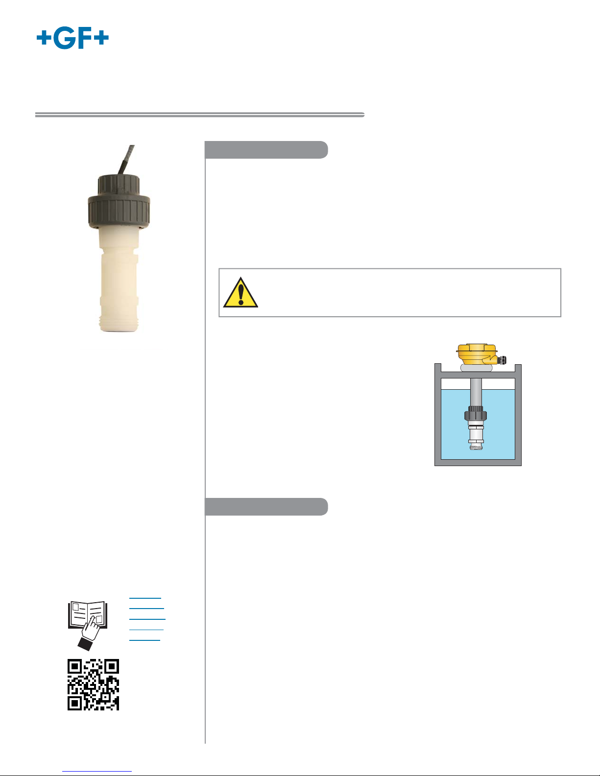
22250 Hydrostatic Level Sensor
Refer to your local Georg Fischer Sales office for the most
current warranty statement.
All warranty and non-warranty repairs being returned must
include a fully completed Service Form and goods must be
returned to your local GF Sales office or distributor.
Product returned without a Service Form may not be
warranty replaced or repaired.
Signet products with limited shelf-life (e.g. pH, ORP, chlorine
electrodes, calibration solutions; e.g. pH buffers, turbidity
standards or other solutions) are warranted out of box but not
warranted against any damage, due to process or application
failures (e.g. high temperature,
chemical poisoning, dry-out) or
mishandling (e.g. broken glass,
damaged membrane, freezing
and/or extreme temperatures).
Thank you for purchasing the Signet line of Georg Fischer
measurement products.
If you would like to register your product(s), you can now
register online in one of the following ways:
• Visit our website www.gfsignet.com.
Under Service and Support click on
Product Registration Form
• If this is a pdf manual (digital copy), click here
Warranty Information
Product Registration
Safety Information
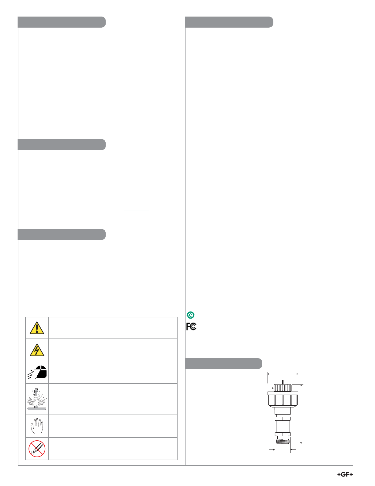
Dimensions
1. Prior to installation or removal:
• Depressurize and vent system
• Drain below sensor level
2. Confirm chemical compatibility before use.
3. Do not exceed maximum temperature/pressure
specifications.
4. Wear safety goggles or faceshield during installation/
service.
5. Do not alter product construction.
6. Dispose of properly; DO NOT INCINERATE!
½ in. (ANSI) or
25 mm (ISO)
Solvent Socket,
PVC-U
34 mm
(1.32 in)
115 mm
(4.55 in)
53 mm
(2.09 in)
General
Compatibility .............................. Signet 8900 Multi-Parameter Controller
Signet 9900 Transmitter
Signet 9950 Dual Channel Transmitter
Wetted Material
Sensor housing ......................... PVDF
Union nut/bushing ..................... PVC-U
Diaphragm................................. Ceramic
Diaphragm seal.........................FKM (optional EPDM)
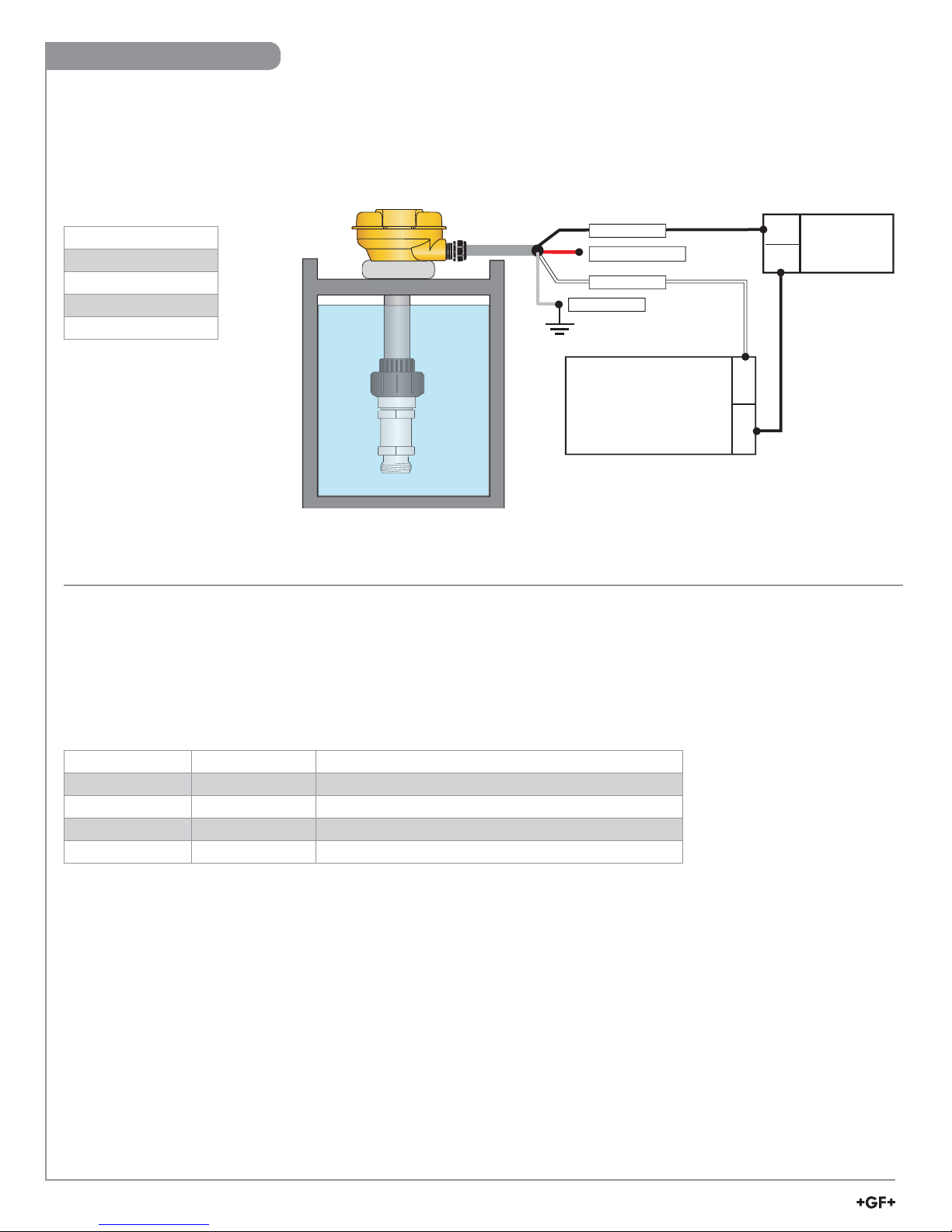
Cable type .................................22 AWG, 3 conductor+capillary tube
Cable length ..............................10 m (32.8 ft) supplied
max. extension 120 m (400 ft)
Operating Temperature............. 15 °C to 85 °C (5 °F to 185 °F)
Storage Temperature................-20 °C to 100 °C (-4 °F to 212 °F)
Operating Pressure:.................. -XU: 0 to 0.7 bar (0 to 10 psig)
-XL: 0 to 3.4 bar (0 to 50 psig)
Electrical
Digital (S3L) Output
Format .......................................Serial ASCII, TTL level 9600 bps.
Accuracy.................................... ±1% of full scale (±0.001 psi)
Power.........................................5 VDC nominal, 1.5 mA max. current
(5 VDC min, 6.5 VDC max)
Reverse polarity and short circuit protected
4 to 20 mA Output
Factory span
-XU.............................................0 to 0.7 bar (0 to 10 psig) =
0 m to 7 m (0 ft to 23 ft) of water
-XL.............................................. 0 to 3.4 bar (0 to 50 psig) =
0 m to 34 m (0 ft to 115.5 ft) of water
Accuracy.................................... ± 32 μA
Resolution.................................. < 5 μA
Response Time .........................< 100 ms
Loop Power Required...............12 to 24 VDC nominal, 22.1 mA max
(10.8 VDC min. to 26.4 VDC max.)
Max. Loop Impedance.............. 100 Ω@ 12 V
325 Ω@ 18 V
600 Ω@ 24 V
Standards and Approvals
CE
RoHS Compliant
Manufactured under ISO 9001 for Quality, ISO 14001 for
Environmental Management and OHSAS 18001 for Occupational
Health and Safety.
China RoHS (Go to www.gfsignet.com for details)
This device complies with Part 15 of the FCC rules.
Operation is subject to the following two conditions:
(1) This device may not cause harmful interference, and,
(2) This device must accept any interference received,
including interference that may cause undesired operation.
Specifications
Caution / Warning / Danger
Indicates a potential hazard. Failure to follow all warnings
may lead to equipment damage, injury, or death
Electrostatic Discharge (ESD) / Electrocution Danger
Alerts user to risk of potential damage to product by ESD,
and/or risk of potential of injury or death via electrocution.
Personal Protective Equipment (PPE)
Always utilize the most appropriate PPE during
installation and service of Signet products.
Pressurized System Warning
Sensor may be under pressure, take caution to vent
system prior to installation or removal. Failure to do so
may result in equipment damage and/or serious injury.
Hand Tighten Only
Overtightening may permanently damage product threads
and lead to failure of the retaining nut.
Do Not Use Tools
Use of tool(s) may damage product beyond repair and
potentially void product warranty.