Yokota YET-501C User manual

YET-501C
PULSE COUNT
POWER
MODE
TIME OUT
TIME
ZERO ADJ.
N・m
01
1
2
3
OFF
P- P
ヨコタデジタル式
トルクテスタ
MODELS: YET-501C
YET-1001C
YET-2001C
YET-5001C
YET-10001C
取扱説明書

-1-
YET-2001C
PULSE COUNT
POWER
MODE
TIME OUT
TIME
ZERO ADJ.
N・m
01
1
2
3
OFF
P- P
■特長
1. 大きいデジタル表示で遠くから見やすく読みとり誤差がありません。
2. タイムアウト設定機能付き(0.1〜9.9秒)0.1秒単位で時間設定でき、立上がり能
力を測定できます。なお、測定ツールにタイマーは必要ありません。
3. 右・左回転共に測定できます。
4. R.O.±0.5%(静荷重)以内の高精度です。
5. アンプの表示パネル部に油またはホコリ付着防止保護カバー付きです。
6. マイコン方式により操作が簡単です。
7.自動パルスカウンタ(打撃数計数)を内蔵しています。
工具管理室・試験室あるいは作業ラインに設
置し、受入検査・定期能力チェック・トルク調整
等に使用でき、ねじ締め管理向上に大いに効
果を示します。
インパルスレンチ(油圧レンチ)・アン
グルナットランナ・ドライバ・ラチェット
レンチ・トルクレンチ(プリセット形を
除く)等に使用できます。
ねじ締付け管理は、締付けツールのチェックから……
ヨコタデジタル式トルクテスタ
MODELS:YET-501C・1001C・2001C・5001C・10001C
(タイマー測定0.1〜9.9秒可能)
締付けツールの高度なトルク精度管理を目的として開発された
トルクテスタです。
▲ ピックアップ
▲アンプ

-2-
※パルスカウンタについて、最大トルクの10%(例YET-2001Cなら20N・m)以上のトルクにて正確に表示しま
す。インパクトレンチにおいては、毎回の打撃トルクは安定していませんので、パルスカウントは使用しないで
ください。
インパルスレンチ(油圧
レンチ)・アングルナッ
トランナ等は50N・m以
内で使用してください。
但し、インパクトレンチ
等、打撃ツールは
35N・m以内で使用して
ください。
インパルスレンチ(油圧
レンチ)・アングルナッ
トランナ等は100N・m以
内で使用してください。
但し、インパクトレンチ
等、打撃ツールは
70N・m以内で使用して
ください。
インパルスレンチ(油圧
レンチ)・アングルナッ
トランナ等は200N・m以
内で使用してください。
但し、インパクトレンチ
等、打撃ツールは
140N・m以内で使用し
てください。
インパルスレンチ(油圧
レンチ)・アングルナッ
トランナ等は500N・m以
内で使用してください。
但し、インパクトレンチ
等、打撃ツールは
350N・m以内で使用し
てください。
5〜50 N・m
0.02N・m
5〜50±0.25N・m
ピックアップ用ケーブル…1本
・プリンタ用パラレル出力(セントロニクス準拠)
・アナログ出力(波形観測端子)
・シリアル出力(RS-232C)
3/8sq×1/2sqアダプタ
20〜100 N・m
0.1N・m
10〜100±0.5N・m
50〜200 N・m
0.1N・m
20〜200±1N・m
100〜500 N・m
0.2N・m
50〜500±2.5N・m
9.9Kg 10.1Kg 10.0Kg 22.7Kg
AC100V〜240V±10% 50/60 Hz・15W
3.0Kg
型 式
適正測定範囲
1目盛
静荷重精度
ピックアップ
電 源
質量
アンプ
標準附属品
出力端子
注意事項
YET- 501C YET-1001C YET-2001C YET- 5001C
………1個
3/8sq×1/2sqアダプタ
………1個
四角ビット
………1個
1/2sq×3/4sqアダプタ
………1個
インパルスレンチ(油圧
レンチ)・アングルナット
ランナ等は1000N・m以
内で使用してください。
但し、インパクトレンチ
等、打撃ツールは
700N・m以内で使用し
てください。
200〜1000 N・m
1N・m
100〜1000±5N・m
22.7Kg
アダプタ無し
YET- 10001C
四角ビット
………1個
仕様諸元

-3-
(1)モードセレクトスイッチ③をOFFにする。
(2)無荷重の状態でゼロ調整で0N・m表示にする。
(3)ピックアップに任意のトルクをかけて、デジタル表示と一致するようにゲイン
アジャスト⑫をドライバで左右に回して調整してください。
P-Pモード時:入力信号のピークをホールドさせて表示し、タイマ終了時にタイムアウト
表示ランプ④が点灯します。そして、設定した時間(約1秒〜3秒)だ
け、表示値を保持して自動的に0にキャンセルします。通常インパルスレ
ンチ・アングルナットランナ等の発生トルクを測定する場合は、この位
置にセットしてください。
OFFモード時:入力信号を遂次データ表示します。ゼロ調整・ゲイン調整時に用いてく
ださい。
8. ゲイン調整(較正方法)
9.プリンタ出力
1テキストのフォーマット
トルクデータカウントデータ印字命令(L/F)
(HOLD1.2.3)
1. ピックアップは水平または垂直な板面にボルトM10(YET-5001C・10001Cは
M14)で確実に固定してください。
2. アンプとピックアップの接続は、センサ用コネクタ⑪とピックアップ用コネクタ⑯
に接続にケーブルを差込んでください。
3. 電源コードをコンセントに接続し、パワースイッチ②をONにしてください。パ
ワースイッチのランプが点灯します。
4. モードセレクトスイッチ③をOFFにして、ゼロアジャスト⑥をトルク表示が0にな
るように左右に回して調整してください。
5. タイムアウト設定デジタルスイッチ⑤によりP - P MODEでの測定時間を0.1秒単位
9.9秒まで設定できますので立上がり能力を測定できます。
6. タイムアウト表示ランプ④について
タイムアウト設定デジタルスイッチ⑤で設定した設定時間になるとタイムアウト
表示ランプ④が点灯しますので測定ツールを止めてください。
7. モードセレクトスイッチ③について
取扱手順 (各名称はP.5外観図を参照してください。)

-4-
10.RS-232C出力
伝送方式調歩同期式
伝送速度4800bps(切換可能、1200・2400・9600bps)
通信方式単一方向(たれながし)
1キャラクタ当たりの構成
スタートビット1bit
データ長8bit(切換可能7bit)
パリティNONE(切換可能偶数パリティ・奇数パリティ)
ストップビット2bit
1テキストのフォーマット
文字コードは、ASCIIコードにて、送る。
ピン配置
ピンNo.
1. 非接続(N.C)
2. TXD送信データ
4. RTS
5. CTS
20. DTR常にレディ(マーク)を出力
7. S.G信号用接地
アンプ側コネクタ:D-Sub25Pメン
パソコンと接続する時は、クロスケーブルを使用してください。
トルクデータカウントデータ 印字命令 (C/R)・(L/F)
ショート(短絡)
1. 規定トルク以上のトルクは加えないでください。
2. テスト中でも温度ドリフトにより多少変化がありますので時々、ゼロ調整してくださ
い。
3. アンプには衝撃を与えないでください。
4. 各部の接続を完了してからパワースイッチをONにしてください。
ご注意
13 1
25 14

-5-
YET-5001C
PULSE COUNT
POWER
MODE
TIME OUT
TIME
ZERO ADJ.
N・m
0 1
1
2
3
OFF
P- P
PRINTER
2A
AC100〜240V
SO/60Hz15W
RS-232C
SENSOR
GAIN
ANALOG
OUTPUT
250
230
130
■アンプ外観図
■ピックアップ外観図
()内寸法は、YET-5001C・10001C用の寸法です。
※仕様・その他記載内容は予告なしに変更する場合がありますので、あらかじめご了承ください。
●表面パネル部
●裏面パネル部
挿入部
型 式 挿入部四角寸法
表面パネル部の名称と機能
①トルクデジタル表示盤
②パワースイッチ(POWER)
③モードセレクトスイッチ(MODE)
④タイムアウト表示ランプ(TIMEOUT)
⑤タイムアウト設定デジタルスイッチ
⑥ゼロアジャスト(ZERO)
⑦ホコリ付着防止保護カバー
⑧パルスカウンタ(PULSECOUNT)表示盤
裏面パネル部の名称と機能
⑩ヒューズボックス(FUSE)
⑪センサ用コネクタ(SENSOR)
⑫ゲインアジャスト(GAIN)
⑬RS232C用コネクタ
⑭プリンタ端子(セントロニクス準拠)
⑮アナログ出力(波形観測端子)
⑯ピックアップ用コネクタ
1
8
7
14
2 3 6 5 4
10 15 11
12
13
16
YET-501C 9.52mm(3/8sq)
YET-1001C 12.7mm(1/2sq)
YET-2001C 12.7mm(1/2sq)
YET-5001C 19.0mm(3/4sq)
YET-10001C 25.4mm(1sq)

YET-501C
PULSE COUNT
POWER
MODE
TIME OUT
TIME
ZERO ADJ.
N・m
01
1
2
3
OFF
P- P
Digital Torque Testers
MODELS: YET-501C
YET-1001C
YET-2001C
YET-5001C
YET-10001C
Instruction Manual
YOKOTA INDUSTRIAL CO., LTD.

-1-
YET-2001C
PULSE COUNT
POWER
MODE
TIME OUT
TIME
ZERO ADJ.
N・m
01
1
2
3
OFF
P- P
■FEATURES
1. Large digital indication prevents miss reading from rather far distance.
2. The testers have time-out setting function and the timing can be adjusted at the unit
of 0.1 second with the range of 0.1~9.9 seconds. So measuring torque at starting-up
point is possible. The tool to be measured does not require timer system.
3. The testers can measure both of right and left rotation.
4. High accuracy (within ± 0.5% of full-scale).
5. Protector cover keeps off oil and dust from the indication panel of the amplifier.
6. Easy operation using micro-computer system.
7. Pulse Counter is built in.
Install the testers in the tool control room, the
test room or the assemblyline for inspection,
periodical performance check and torque adjust-
ment.
YOKOTA testers will give good effect on the
improvement of screw tightening control.
The testers are used for Impact Wrenches,
Impulse Wrenches, Angle Nut Runners,
Drivers, Ratchet Wrenches, and Torque
Wrenches (except the pre-set type).
YOKOTA DIGITAL TORQUE TESTERS
MODELS:YET-501C・1001C・2001C・5001C・10001C
(Measurement by timer from 0.1 to 9.9 seconds, is possible.)
The testers were developed to realize high accurate torque control.
▲Pick-up
▲Amp.

-2-
※For the pulse counter, the torque from 10% or more of the maximum torque (e.g. 20 N・m for YET-2001C)
can be accurately displayed.However, for impact wrenches, since each hitting torque is not stable, do not use
a pulse counter. Pulse counter should not be used for impact type tools as their impact torque is not stabilized.
Above measuring range is
limited impulse tools and
nutrunner only. Impact
type tools should be
measured within 70% of
above specified measur-
ing range (35Nm or less).
Above measuring range is
limited impulse tools and
nutrunner only. Impact
type tools should be
measured within 70% of
above specified measur-
ing range (70Nm or less).
Above measuring range is
limited impulse tools and
nutrunner only. Impact
type tools should be
measured within 70% of
above specified measuring
range (140Nm or less).
Above measuring range is
limited impulse tools and
nutrunner only. Impact
type tools should be
measured within 70% of
above specified measur-
ing range (350Nm or
less).
Above measuring range is
limited impulse tools and
nutrunner only. Impact
type tools should be
measured within 70% of
above specified measuring
range (700Nm or less).
5~50
N・m
0.02 N・m
5〜50±0.25 N・m
One set of cable for pickup
・Parallel output for printer (conform to Centronics)
・Analog output (terminal for waveform measuring)
・Serial output (RS-232C)
1pce.…3/8”sq ×
1/2”sq adapter
20~100 N・m
0.1 N・m
10〜100±0.5 N・m
50~200 N・m
0.1 N・m
20〜200±1 N・m
100~500 N・m
0.2 N・m
50〜500±2.5 N・m
9.9 Kg (21.8lb) 10.1 Kg (22.0lb) 10.0 Kg (22.0lb) 22.7 Kg (50.0lb)
AC100V〜240V±10% 50/60 Hz・15W
3.0 Kg (6.6lb)
Model
Measuring Range
Scale Unit
Static Load Precision
Pick-up
Required Power
Amplifier
Weight
Standard
Accessories
Output
Terminals
Notes
YET- 501C YET-1001C YET-2001C YET- 5001C
1pce. … square bit
200~1000 N・m
1 N・m
100〜1000±5 N・m
22.7 Kg (50.0lb)
YET- 10001C
1pce. … square bit
Specifications
1pce.…3/8”sq ×
1/2”sq adapter
1pce.…1/2”sq ×
3/4”sq adapter ー

-3-
(1) Set the mode-dial “OFF”.
(2)
Set 0 kgf・cm indication by means of ZERO-adjustment under no load condition.
(3) Charge some torque on the Pick-up and adjust it turning the GAIN-adjust by a
driver so that the digital indication may accord to the torque.
It holds the peak of input signal and indicate the value. At the point of
timer-finish, the time-out indication lamp(4) will light. It holds the indicated
value within the setting time (1~3 sec.), and after that it cancels automati-
cally showing 0 kgf・cm. Usually this mode is applied to measure the
torque of Impulse Wrenches, Angle Nut Runners, Impact Wrenches, etc.
It indicates the input signals each time at data-indication. Apply this mode
for ZERO-adjustment and GAIN-adjustment.
8. GAIN-adjustment ( How to calibrate )
9.Printer output
Frame format of one text.
Torque data Count data Print order (L/F)
(HOLD1.2.3)
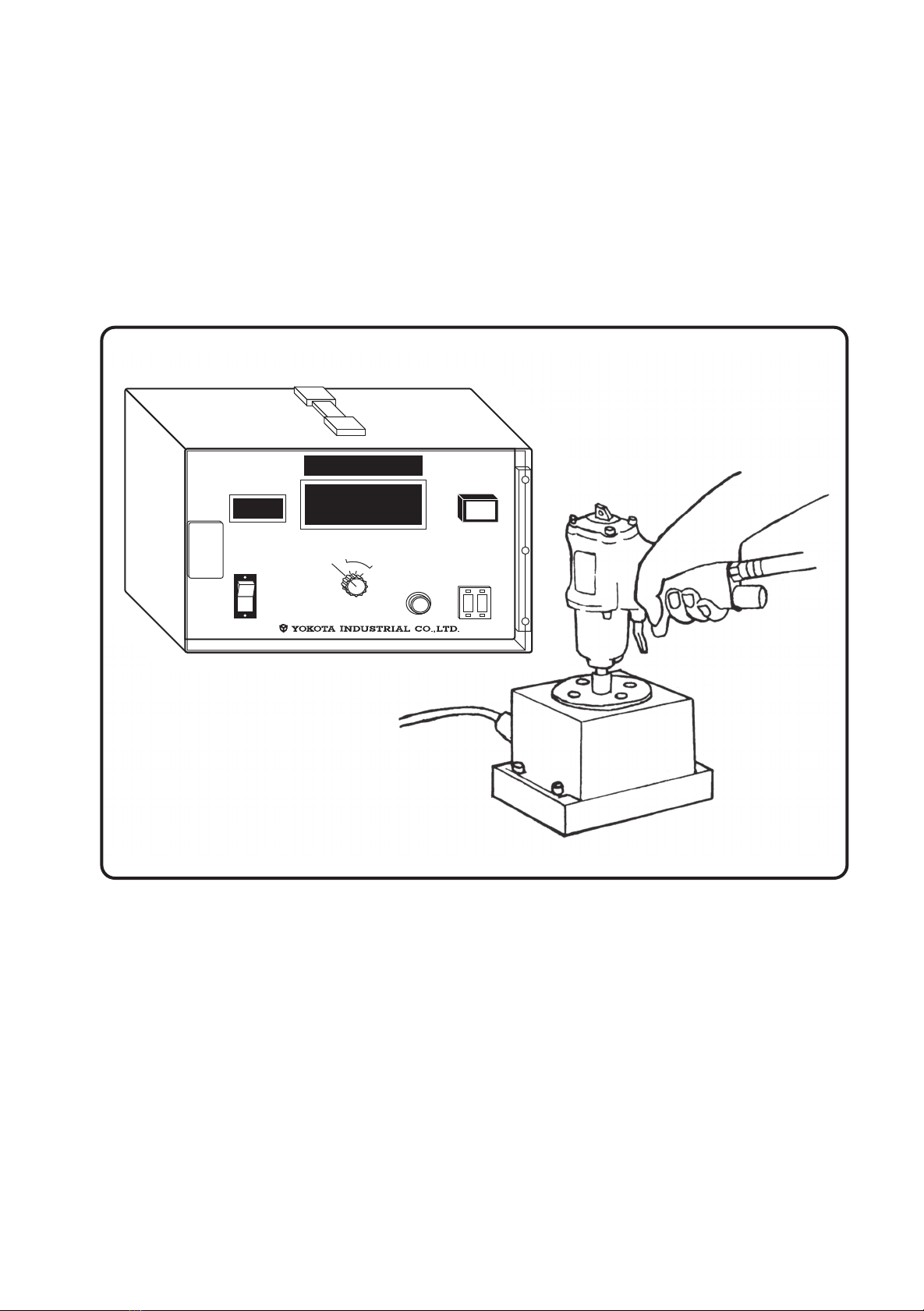
1. Fix the pick-up firmly using M10 bolts on flat or vertical plate or hold it on a vice
firmly. (For YET-5001C ・10001C, M14 bolts are used.)
2. In order to connect the amp. to the pick-up, install the connect cable into the connec-
tor(11) and the connector(16).
3. Connect the input code to the power source and set the power switch(2) on. Lamp
of power switch will light.
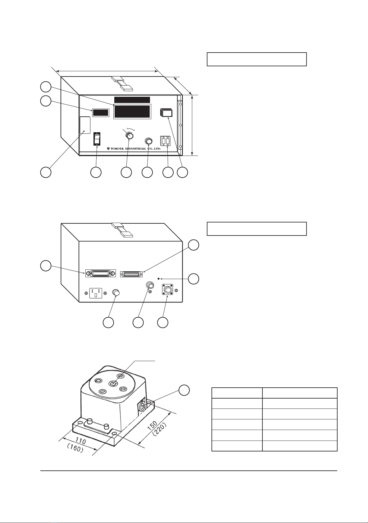
4. Turn off the Mode dial(3), and turn the ZERO adjust(6) right and left to adjust.
5. As you can set the measuring time with the unit of 0.1 second upto 9.9 seconds
under P-P mode by means of the digital switch(5) for setting time-out, it is possible
to measure the starting torque.
6. Time-out indication lamp(4)
Reaching the setting time set by the time digital switch(5), the time-out lamp(4) will
light, and stop the rotation of the measuring tool.
7. Mode dial(3)
HOW TO OPERATE
(Foreachname,refertothepage5,exteriordrawing.)
P-P mode :
OFF mode :

-4-
10. RS-232C output
Transmission system : Start-stop synchronization
Transmission speed : 4800bps (changeable : 1200 , 2400 , 9600 bps)
Way of communication : One-side direction
Frame format per one character.
Start bit 1bit
Data length 8bit (changeable : 7 bit)
Parity NONE (changeable : Even number parity, Odd number parity)
Stop bit 2bit
Frame format of one text.
Letter code are sent by ASC Ⅱcode.
Pin position
Pin No.
1. Disconnection (N.C)
2. TXD Transmission Data
4. RTS
5. CTS
20.DTR”Ready” mark is always output.
7. S.GThe place for signal
The connector on the amplifier side:D-Sub25P
Use the cross cable when connected with a personal computer.
Torque data Count data Print order (C/R)
Short circuit
1. Do not charge such torque as being over the specified torque.
2. During test, apply Zero-adjust from time to time because there are some differences
due to temperature-change.
3. Do not give any shock on the amplifier.
4. After all connections being ready, set the Power-Switch “ON”.
NOTE
13 1
25 14

-5-
YET-5001C
PULSE COUNT
POWER
MODE
TIME OUT
TIME
ZERO ADJ.
N・m
0 1
1
2
3
OFF
P- P
PRINTER
2A
AC100〜240V
SO/60Hz15W
RS-232C
SENSOR
GAIN
ANALOG
OUTPUT
250
230
130
■Exterior of Amplifier
■Dimension of Pick-up
Size in ( ) is for YET-5001C・10001C
※Please note that specifications and other contents are subject to change without notice.
●Front Panel
●Back Panel
Tool Slot
Model Slot square size
Name and function of the front panel
1. Digital display
2. Power switch (POWER)
3. Mode select switch (MODE)
4. Time out display lamp (TIME OUT)
5. Time out setting switch
6. Zero adjust (ZERO)
7. Dustproof protective cover
8. Pulse count display (PULSE COUNT)
Name and function of the back panel
10. Fuse box (FUSE)
11. Connector for sensor (SENSOR)
12. Gain adjust (GAIN)
13. RS232C connector
14. Printer terminal (Conform to Centronics)
15. Analog output (terminal for waveform
measuring)
16. Connector for Pick-up
1
8
7
14
2 3 6 5 4
10 15 11
12
13
16
YET-501C 9.52mm(3/8sq)
YET-1001C 12.7mm(1/2sq)
YET-2001C 12.7mm(1/2sq)
YET-5001C 19.0mm(3/4sq)
YET-10001C 25.4mm(1sq)
This manual suits for next models
4
Table of contents