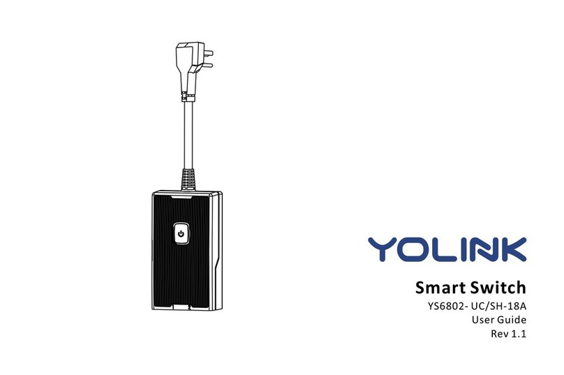
Yolink YS5705-UC User manual

User Guide
YS5705-UC
In-wall Switch

Contents
Introduction············································· 1·················
Features··················································· 2···············
Product Requirements································ 2·················
Set Up In-wall ch································ ·· 3 Swit ·· ··················
Using YoLink App with In-wall Switch·································11
Maintaining the ················ ······· In-wall Switch ··············· ··19
Specifications·································· ························ ·21
Installation··································································7
YoLink Control ················· ······ ················16··········· ·· ·····
Troubleshooting ·················· ················· 22········· ··········· ··
C Service & Warranty ················· · 23ustomer ···················· · ·

Introduction
In-wall Switch, is a standard, single-pole, wall light switch that can be controlled via your
iOS or Android devices. Along with the YoLink App, connect the In-wall Switch to your
home network, then control your lights and create custom lighting automation from
anywhere, at anytime with an Internet connection.
1
LED lights can show the current status of device. See the explanation below:
White
The switch is on.
POWER BUTTON
Blinking Blue
Connecting to cloud.
Fast Blinking Blue
Set up connection with devices.
Irregular Blinking Blue
Remove connection with devices.
Irregular Slow Blinking Blue
Factory resetting.
Slow Blinking Blue
Updating.
Red
The switch is off.

Features
2
Control from anywhere - Control your In-wall Switch remotely via YoLink App on your iOS
or Android device.
Timer & Schedule - Automatically turn on or off light after or at a certain time.
Scene - One-click control. Tap the scene button to automatically turn on or off your In-wall
Switches and action of other devices.
Automation - Set up rules for “If this then that” function.
YoLink Control - No internet is required, turn on or off your In-wall Switch when you set up your
switch with a sensor or remote controller.
Voice Control - Use Alexa or Google Assistant to control your devices with voice commands.
Product Requirements
1. A YoLink Hub.
2. A smartphone or tablet running iOS 9 or higher; Android 4.4 or higher.
4. Neutral wire required.
5. Single-pole light switch. The electrical box should be more than 2 inches deep.
3. In-wall installation with hardwired connections.

3
Set Up In-wall Switch
Follow the steps below to set up your In-wall Switch via YoLink App.
Step 1: Set up YoLink App
Get the YoLink App from the Apple App Store or Google Play.

If you don’t have a YoLink account, tap Sign up for an account and follow the steps
to sign up an account.
Open the App. Use your YoLink account to log in.
Step 2: Log in or sign up with YoLink account
4

Step 3: Add device to YoLink App
b. Room - Choose a room for In-wall Switch.
a. Name - Name In-wall Switch.
You can customize the name, set the room, add to/remove from favourite.
Tap the “ ” in YoLink App. Scan the QR Code on the device.
Tap the “Bind Device” to add the device to your YoLink account.
5
Follow the Installation to install the device, power it on. And the device is ready to go.
c. Favourite - Click “ ” icon to add/remove from Favourite.
Neu tral W ire
Loa d Liv e
a
b
c

Step 4: Connect to the cloud
Follow the following page to install the device first.
Power on the In-wall Switch and your device will connect to the cloud automatically.
Note
Make sure you hub is connected to internet.
6
Cloud
Internet

1. Turn off the power to the switch at the main circuit breaker or fuse panel.
Installation
Important
All wiring connections must be made after power down to avoid personal injury and/or
damage to the switch.
This device is intended for installation in accordance with the national electric code and
local regulations in the United States, or Canadian electrical code and local regulations
in Canada.
If you are unsure or uncomfortable about performing this installation, consult a qualified
electrician.
The fixture controlled by the in-wall switch must not exceed 960 watts (incandescent),
800w (10A) resistive or hp motor. The switch is designed only for use with permanently
installed fixtures.
WARNING: SHOCK HAZARD
May result in serious injury or death.
Turn off power at circuit breaker or
fuse before installing.
7

2. Unscrew and remove the switch plate; then use a voltage tester to make sure that the
circuit is dead.
3. Unscrew the switch from the electrical box and pull it out with the wires still attached.
Hot Wire
Ground
Two or three wires will be attached to the switch: an incoming hot wire, which is black; a
return wire, which carries the load to the fixture and may be black, red, or any other color
except green; and sometimes a grounding wire, which is green or bare copper. There
may be other wires in the box, but you are only dealing with the ones connected directly
to the switch.
You may find a white wire that has black tape on it connected to the switch. This tape
indicates that the white wire is being used as a black or colored wire in the switch leg, so
it’s not neutral.
8

4. Com p a r e y our new swi t c h w i t h the one yo u ’ r e r eplacing to fi n d t he corresp o n d i n g
locat i o n s f o r the elec t r i c a l screw con n e c t o r s.
5. Attach the first wire you unscrew to the same-colored screw on the new switch as it was
on the old; do the same with the second.
Because the power is off, you can match up the connectors the easy way: Instead of
disconnecting all the wires at once and possibly getting confused, unscrew and connect
one wire at a time.
To connect a wire to a terminal, strip off about 1/2 inch of insulation, using a wire stripper,
and twist the end into a clockwise loop with long-nose pliers. The loop must wrap at least
two-thirds but no more than three-quarters of the way around the terminal screw. Hook the
wire clockwise around the screw so when you tighten the screw with a screwdriver, the
clockwise force of the tightening screw makes the loop wrap tighter around the screw.
Load Li v e
Neutr a l Wir e
L
N
9

7. Snap on the switch plate and turn .power on at circuit breaker
6. Gently push the new, wired switch back into the electrical box and screw it in place.
Screw the switch
‘Snap’
Snap on the plate Turn on the power
10

Using YoLink App with In-wall Switch
Details
a. Name - Name In-wall Switch.
b. Room - Choose a room for In-wall Switch.
e. Power on Again Status - Choose power on again
status for In-wall Switch.
You can customize the name, set the room, set power on again status, add to/remove from
favourite, check device history.
Tap the “In-wall ” in App to go to its controls.Switch
f. Delete – The device will be remove from your account.
d. History - Check the history log for the Switch.
Tap the icon for each of the settings you want to
personalize.
Tap the “ ” icon at the top-right corner to go to
details.
c. Favourite - Click “ ” icon to add/remove from
Favourite.
11
a
b
c
d
e
f

Timer
With YoLink App, you can set up a timer to turn on or/and off your .In-wall Switch
Tap the “In-wall ” in App to go to its controls.Switch
Tap “Timer” for timer setting.
Choose action from “ON”, “OFF”, or “ON then OFF”.
Set the timer duration in Hours and Minutes.
Note
One timer will run only once. You can set a new
timer after the timer has already run or once
you cancel it.
The Timer here is running at device without internet.
Tap “ ” icon to save.
12

Schedule
You can create ON/OFF schedules to automate your plugged-in devices to work around
your home and work schedules.
Within the Add Schedule screen, set the time,
your preferred state (“ON”,”OFF” or “ON then
OFF”) for the connected device, and repeating
frequency.
Note
Tap “Schedule” to open the Schedule screen,
tap “ ” to add a new schedule.
Activate or deactivate the schedule at schedule
screen.
Swipe left each schedule to edit or delete it.
You can keep maximum 6 schedules at one time.
The schedule here is running at device without
internet.
You may try to add schedule at Automation
where you can add as many as you want. The
automation setting is saved in cloud.
Tap the “In-wall ” in App to go to its controls.Switch
Tap “ ” icon to save.
13

Scene
Set one-click control for multiple devices in your YoLink App. You only run a scene via your
YoLink App.
To set a Scene, you will be able to put one or more
devices under this scene, and define their actions
and/or states.
Tap “ ” to create your own Scene.
Tap “Smart” to switch to Smart Screen.
Swipe left any Scene order to edit or delete it.
To execute a Scene, you may tap any scene at
“Smart” or “Favourite” if you mark it as favourite.
Note
You must have at least one YoLink Device in order
to create a Scene.
14

Automation
Automation allows you to set up “If This Then That” rules so the devices could act
automatically.
Tap “Smart” to switch to Smart screen and tap
“Automation”.
To set an Automation, you will need to set a
trigger time, local weather condition, or choose a
device with certain stage as a triggered condition.
Then set one or more devices, scenes to be
executed.
Tap “ ” to create an automation.
15

YoLink Control is our unique “device to device” control technology. Under YoLink Control,
the devices can be controlled without internet or Hub. Device which send out command
is called controller(Master). Device which receive command and act accordingly is called
responder(Receiver). Controller and responder list will show you below.
YoLink Control
You will need to set it up physically.
YS6602-UC YoLink Plug
Responder List
YS6604-UC YoLink Plug Mini
YS5705-UC In-wall Switch
YS6704-UC In-wall Outlet
Continuously ..updating
YS6801-UC Smart Power Strip
YS7704-UC Door Sensor
Controller List
YS7705-UC Garage Door Sensor
YS7903-UC Leak Sensor
Continuously ..updating
YS3603-UC YoLink Remote
YS7804-UC Motion Sensor
YS6604-UC YoLink Plug Mini
YS5705-UC In-wall Switch
YS6704-UC In-wall Outlet
YS6801-UC Smart Power Strip
YS6602-UC YoLink Plug
16

Find an in-wall switch as controller(Master). Hold the power button for 5-10 seconds,
the light will flash blue quickly.
After pairing succeed, the light will stop flashing.
Find another action device as responder(Receiver). Hold the power/set button for 5-10
seconds, the device will enter pairing mode.
When the in-wall switch turns on, the responder will turn on as well. When the in-wall switch
turns off, the responder will turn off as well.
Pairing
Find a switchcontroller(Master) in-wall . Hold the
power button for 10-15 seconds, the light will flash
irregular blue.
The above two devices will unpair by themselves
and the light stops flashing.
Unpairing
After unbundling, When the in-wall switch turns
on, the responder will no longer turn on. When
the in-wall switch turns off, the responder will
no longer turn off.
Find a Receiverresponder( ) action device. Hold
the button for 10-15 seconds, the power/set
device will enter un-pairing mode.
17
POWER BUTTON

YoLink Control Diagram
Unpaired
turn offturn off
Paired
opened
turn onturn off
closed opened
closed
18
Table of contents
Other Yolink Switch manuals