York 2AC02700801 User manual

GENERAL
This control panel provides the interface between the furnace
and the heat pump system.
The Heat Pump is the primary source of heat for the building
when the outdoor temperature is above the balance point. The
furnace provides supplemental heat when the outdoor tem-
perature is below the balance point. When the outdoor tem-
perature is below the setting of the low temperature cut-off,
only the furnace can operate.
Acomplete Maxi-Mizer Add-On System consists of the follow-
ing components (all shipped separately).
1. Outdoor Unit - E*FH with YorkGuard control
2. Indoor Coil - G1FD, G3US, G3HC, G1UA, G3UA or G2UT
3. Control Panel - 2AC02700801
4. Heat Pump Thermostat (2TH11702224, 2TH11702424, or
2ET11700224)
5. Furnace (gas, oil or electric)
SeetheE*FHtechnicalguidefortheapprovedcombinationsof
indoor coils and units.
The indoor coil must be installed down-stream of the furnace
discharge. The furnace/heat pump orientation may be upflow,
horizontal or downflow. Make sure that the indoor coil is being
applied within its application limitations.
LIMITATIONS
The installation of this unit shall be in accordance with all the
regulations of the authorities having jurisdiction. All lo-
cal/nationalcodesandstandardsonelectricalsystem,fuel-burning
appliances, and mechanical refrigerant systems must be ob-
served.
Observealloftheapplicationlimitationsandclearancerequire-
ments for the outdoor unit, the furnace and the indoor coil.
ELECTRICAL DATA FOR CONTROL PANEL
The voltage limitations of the furnace must be determined by
the installer.
Determine the CFM capability of the furnace and the CFM re-
quirement of the heat pump system, and make sure the CFM's
are compatible. If the furnace can't deliver enough air or deliv-
ers too much air, the system will not operate properly. Do not
add a heat pump to any furnace where the existing furnace
blower can not provide sufficient air flow.
WARNING:Some indoor coils may be shipped with a substan-
tialrefrigerantcharge.Neverallowafurnacetoop-
erateon the heatingcyclewithoneofthesecoils in
place but not connected to the rest of the heat
pump system.
INDOOR COIL - LOCATION AND MOUNTING
Theindoorcoilmustbeinstalledin the discharge air side of the
furnace. The coil should be centered on the furnace discharge
in a factory supplied casing. No modification of any part of the
furnace is permitted.
The casing provides an insulated enclosure which properly lo-
catestheindoorcoil attheminimum requireddistancefromthe
furnace.At least1"spacemustbemaintainedbetweenthefur-
nace discharge and the underside of the coil drain pan.
See coil installation instruction for more information concern-
ing coil mounting.
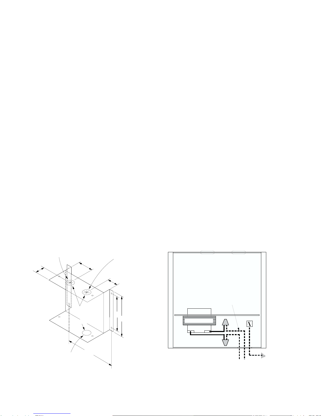
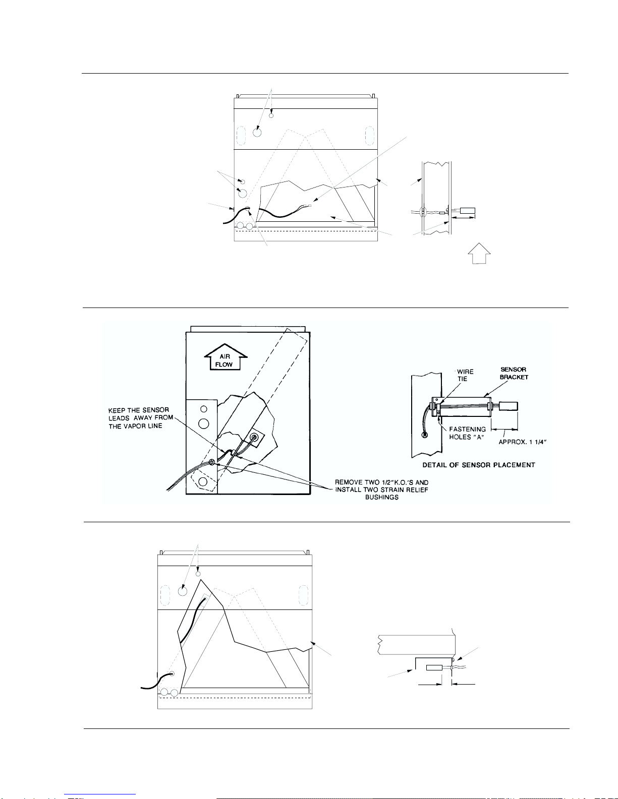
CONTROL PANEL MOUNTING
The control panel should be mounted on a nearby wall within the
reachof its 10 footlong sensor wire.This wire shouldbe carefully
routed from the control panel into the indoor coil casing.
CAUTION: Avoidroutingthesensorwireoveranysharpsheet
metal edges or any high temperature surfaces.
Mounting holes and screws are provided to secure the control
panel to the mounting surface. See Figure 1 for control panel
dimensions and hole locations.
NOTE: The control panel should never be mounted in or on
the furnace enclosure or discharge plenum. During
heating operation, high temperatures could damage
some of its components.
BRACKET AND SENSOR INSTALLATION
The mounting bracket and sensor location varies with the type
of coil and the application of that coil. Notice mounting bracket
fastening holes shown in illustration below:
®
MODEL 2AC02700801
Power Supply*
Voltage Min. - Max.
Min. Ckt. Amp.
Max. Fuse Size, Amps
Min. Wire Size (60°C), AWG
115-1-60
103 - 127
0.5
15
14
*PowersupplyfortheAdd-oncontrolpanelonly.Seetheinstallationinstructionsandtheunit
instructions and the unit data plate for the power supply of the outdoor unit.
CAUTION
THE ENCLOSED INSTALLATION INSTRUCTIONS AND ANY APPLICABLE
LOCAL, STATE, AND NATIONAL CODES INCLUDING, BUT NOT LIMITED
TO, BUILDING, ELECTRICAL, AND MECHANICAL CODES.
THIS PRO DU CT M US T BE IN STALLED IN STRICT CO M PLIANCE W ITH
WARNING
OPERATION OF THE PRODUCT COULD CAUSE PERSONAL INJURY
OR PROPERTY DAMAGE.
INCORRECT INSTALLATION MAY CREATE A CONDITION WHERE THE
MODELS 2AC02700801 035-14216
ADD-ON CONTROL PANEL
FOR USE WITH
E*FH HEAT PUMPS
INSTALLATION INSTRUCTION Supersedes: Nothing 545.01-N10Y (1296)

SeeFigures 3, 4, 5 or 6 to determine the mounting bracket and
sensor location.
Select the appropriate figure and the appropriate application:
upflow, horizontal or counterflow. Mount the bracket (required
with slant, horizontal “V” type and counterflow coils only) with
the two screws provided.
NOTE: Slant coils and horizontal “V” type coils use fastening
holes “A”. See Figures 3, 4 & 6. Counterflow coils use
fastening holes “B” as indicated in Figure 5.
Two 1/2" strain relief bushings are supplied with the control
panel for sensor wire protection where it passes thru the coil
casing. These bushings are to be installed through the 1/2"
K.O. holes found in the outer coil casing and the coil fill plate.
See Figure 3. The end of the wires must be stripped 1/4" for
bonnet sensor connection.
CONTROL PANEL WIRING
Route the power wiring through the 7/8" hole in the enclosure
near the transformer. Route the low voltage wiring through the
two 5/8" bushings to the low voltage blocks for the heat pump
(10terminals)andthefurnace(3 terminals).Typicalfield wiring
is shown in Figure 2.
Additionalpower wiring canbe brought thru the knockoutadja-
cent to the power supply wiring.
WIRING CONNECTIONS
All field wiring must comply with the limitations listed in this in-
struction, including compliance with all local codes, the Na-
tional Electrical Code, and the Canadian Electrical Code. See
Figure 7 for field wiring connections when the Add-On Control
isappliedwithafurnacehavingafactorysuppliedblowerrelay.
NOTE: All furnaces must have a blower relay.
WIRING LABEL
Awiring label of the complete Add-On Control is provided with
the control box for field installation over the existing outdoor
unit wiring label. Peel off the protective paper, and apply it to
the proper location on the outdoor unit access panel.
CONTROL PANEL OPERATION
The control system for the add-on heat pump utilizes all of the
protection features offered with the standard split system heat
pump. Cooling operation and first stage heat operation are
identical to the split system heat pump. At outdoor tempera-
turesbelowthebalancepoint,supplementalheatcanoperate.
When the thermostat calls for second stage heat and the out-
doortemperatureisbelowthebalancepoint,thefurnacewillbe
energizedthrough add-on control relay3R and thefurnace will
begin to supply additional heat.
When the air temperature entering the indoor coil reaches ap-
proximately 95°F, the heat pump will be shut down and the
YorkGuard Solid State Module will not allow the system to re-
start for 5 minutes. The furnace will operate until the second
stage thermostat is satisfied. The furnace blower will continue
to circulate the residual furnace heat.
When the air temperature entering the indoor coil drops to ap-
proximately 93°F and the 5 minute delay of the YorkGuard is
satisfied,the heatpumpwillrestartandwilloperateuntileither:
(1)thefirststageofthethermostatissatisfiedor (2)thesecond
stage heat of the themostat closes and requires another fur-
nace cycle.
When the outdoor temperature drops below the low tempera-
ture cutoff, the heat pump will be de-energized. The furnace
will cycle with the first stage of the thermostat, and the blower
will cycle with the furnace.
When the heat pump system initiates a defrost cycle, the furnace
will cycle to prevent cold drafts. The furnace will operate until the
air temperature entering the indoor coil rises to approximately
109°F and will re-cycle when the air temperature entering the in-
door coil drops to approximately 90°F. Upon termination of de-
frost, the furnace cannot operate until the air temperature
entering the indoor coil drops below approximately 90°F.
2 Unitary Products Group
545.01-N10Y
1 1/4
2 3/16
1 1/2
5 1/2
7
7 3/16
FURNACE
CONTROL
WIRING
ROOM THERMOSTAT & HEAT PUMP
CONTROL WIRING
7/8" HOLE
7/8" STAR
GROMMETS
POWER
WIRING
ADD ON CONTROL
TRANSFORMER GRD. LUG
115 1 60
POWER SUPPLY*
* 18 AWG MINIMUM
2 CONDUCTOR
WITH GROUND
* 14 AWG MINIMUM
2 - CONDUCTOR
WITH GROUND
FIG. 1 - CONTROL PANEL DIMENSIONS
AND MOUNTING HOLE LOCATION FIG. 2 - CONTROL PANEL FIELD POWER WIRING

Unitary Products Group 3
545.01-N10Y
AIR
FLOW
REFRIGERANT CONNECTIONS G*FD COILS
COIL
CASING
FRONT
PANEL
"A"
COIL
FILL
PLATE
(G*UA) REMOVE 1/2" KO
AND INSTALL GROMMET
DETAIL OF SENSOR PLACEMENT
CROSS SECTIONAL VIEW
REMOVE 1/2" K.O.
REFRIGERANT
CONNECTIONS
G*UA COILS
(G*FD) REMOVE 1/2" KO
AND INSTALL GROMMET
APPROX.
1-¼"
FIGURE 3 - SENSOR PLACEMENT - G*UA, G2UT AND G-FD (UPFLOW & HORIZONTAL) COILS
FIGURE 4 - SENSOR PLACEMENT (WITH BRACKET) - FOR G3US COIL
FIGURE 5 - G-FD (DOWNFLOW APPLICATION) COILS
REFRIGERANT CONNECTIONS G*FD COILS
FRONT
PANEL
DETAIL OF SENSOR PLACEMENT
APPROX.
1-¼"
BRACKET
FASTEN
TO
ENDSHEET

S1
S2 S1
S2
Unitary Products Group
P.O. Box 1592, York, Pennsylvania USA17405-1592
Subject to change without notice. Printed in U.S.A.
Copyright by York International Corporation 1997. All Rights Reserved. Code: SBY 545.01-N10Y
FIGURE 6 - SENSOR PLACEMENT (WITH BRACKET) FOR HORIZONTAL APPLICATION OF G3HC COILS
FIGURE 7 - FIELD WIRING DIAGRAM (Furnace with factory supplied blower relay)
Other York Control Panel manuals
Popular Control Panel manuals by other brands

Siemens
Siemens MJ-X Installation and operation manual

Cooper
Cooper Scantronic 9448 user guide

Mitsubishi Electric
Mitsubishi Electric GOT SIMPLE GS2110-WTBD user manual

Intermatic
Intermatic PE10000 Series Installation, operation & service manual

SALUPO
SALUPO SOFT START PLUS 1 Instruction and installation manual

Topcon
Topcon DIGISTAR TMR4610 Operator's manual