YOUESS U Series User manual

Solar charge inverter
USER MANUAL
Hybrid Inverter
ln order to prevent improper operation before use, please carefully read this manual.

2
9.2 GENERATOR OPERATION NOTES ............................................................................................................61
9.3 GENERATOR SETTING .................................................................................................................................61
10. INVERTER PARALLEL GUIDE........................................................................................................................... 63
10.1 PARALLEL SYSTEM DIAGRAM ................................................................................................................. 63
10.2 PARALLEL COMMUNICATION CABLE CONNECTION...................................................................... 67
10.3 PARALLEL OPERATION NOTES............................................................................................................... 67
10.4 PARALLEL SYSTEM SETTING ................................................................................................................... 68
11. ADVANCED MODE OPERATION GUIDE ..................................................................................................... 69
11.1 ADVANCED MODE INTRODUCTION..................................................................................................... 69
11.2 ADVANCED MODE SETTING................................................................................................................... 70
12. FAULT DIAGNOSIS AND SOLUTIONS.......................................................................................................... 72
1
CONTENTS
1. NOTES ON THIS MANUAL................................................................................................................................. 3
1.1 SCOPE OF VALIDITY....................................................................................................................................... 3
1.2 TARGET GROUP.............................................................................................................................................. 3
1.3 SYMBOLS USED.............................................................................................................................................. 3
2. SAFETY.................................................................................................................................................................... 4
2.1 IMPORTANT SAFETY INSTRUCTIONS ....................................................................................................... 4
2.2 EXPLANATION OF SYMBOL ....................................................................................................................... 8
3. INTRODUCTION ................................................................................................................................................... 9
3.1 BASIC FEATURES ............................................................................................................................................ 9
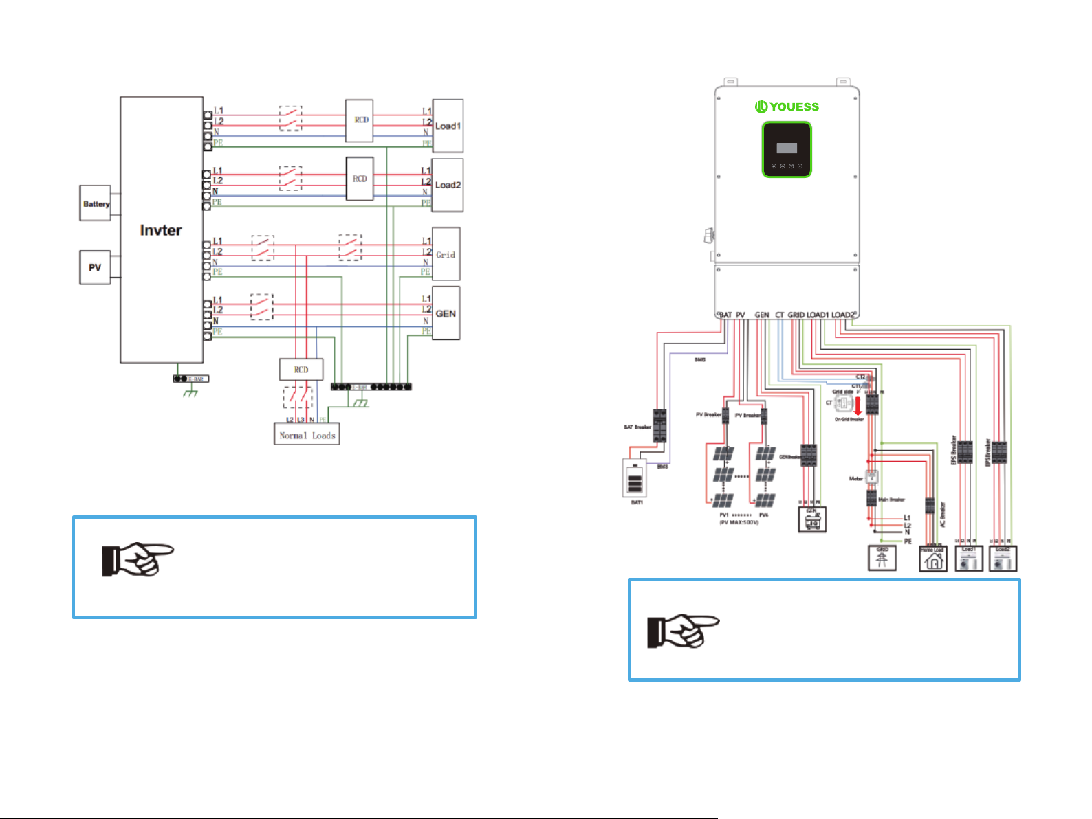
3.2 SYSTEM DIAGRAM........................................................................................................................................ 9
3.3 WORK MODES ..............................................................................................................................................12
3.4 DIMENSION ................................................................................................................................................... 13
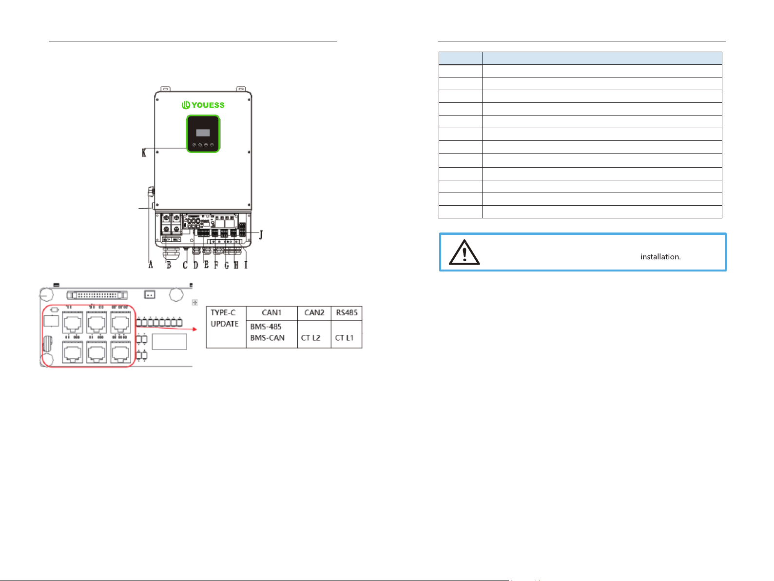
3.5 TERMINALS OF PV INVERTER ...................................................................................................................14
4. TECHNICAL PARAMETERS................................................................................................................................16
4.1 INVERTER SPECICATION .............................................................................................................................16
5. INSTALLATION ..................................................................................................................................................... 18
5.1 CHECK FOR PHYSICAL DAMAGE ..............................................................................................................18
5.2 PACKING LIST ................................................................................................................................................18
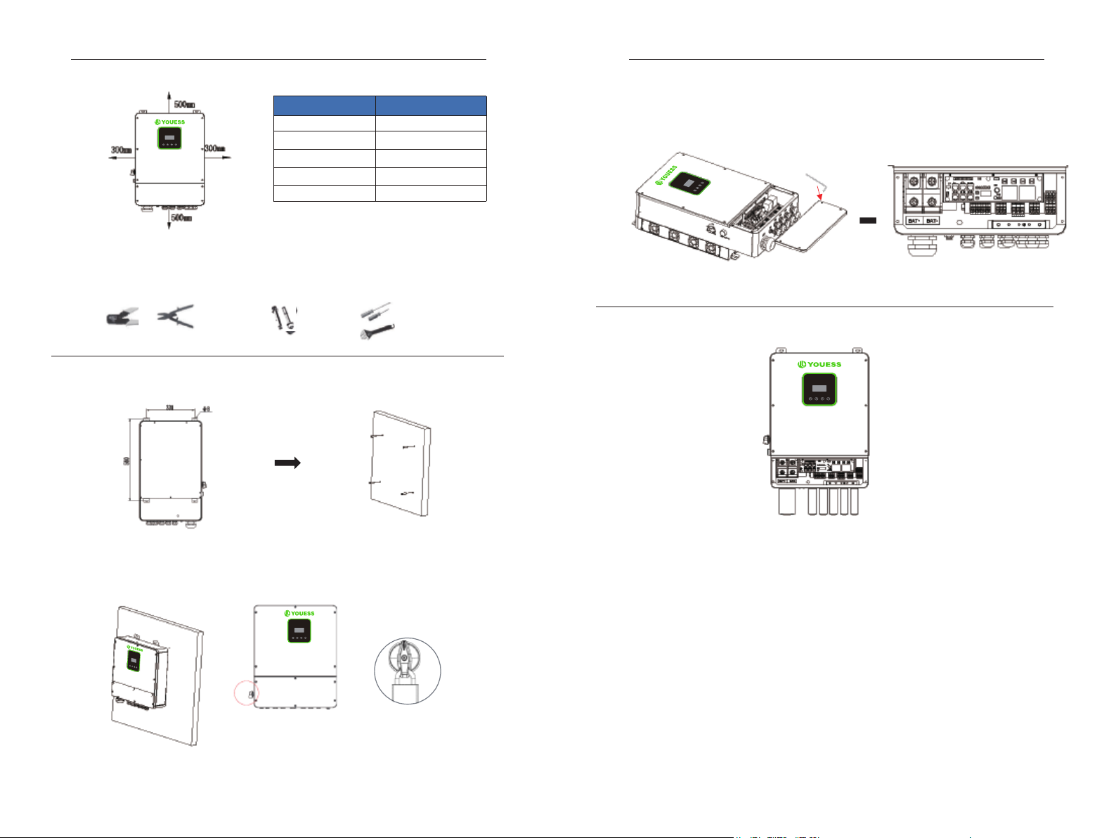
5.3 MOUNTING ...................................................................................................................................................18
6. ELECTRICAL CONNECTION ............................................................................................................................ 22
6.1 PV CONNECTION ........................................................................................................................................ 22
6.2 GRID CONNECTION (GEN CONNECTION) .......................................................................................... 23
6.3 BACK-UP:LOAD1 AND LOAD2 CONNECTION ...................................................................................... 24
6.4 BATTERY CONNECTION............................................................................................................................ 26
6.5 WIFI CONNECTION (OPTIONAL)............................................................................................................ 28
6.6 GPRS CONNECTION (OPTIONAL).......................................................................................................... 28
6.7 CT INSTALLATION INSTRUCTIONS......................................................................................................... 29
6.8 E-STOP INSTALLATION .............................................................................................................................. 30
7. LCD OPERATION .................................................................................................................................................31
7.1 CONTROL PANEL .......................................................................................................................................... 31
7.2 INSTRUCTIONS FOR LED INDICATOR.....................................................................................................31
7.3 INSTRUCTIONS FOR THE USE OF THREE MODES ............................................................................. 32
8. LCD OPERATION ................................................................................................................................................ 35
8.1 LCD INTERFACE ............................................................................................................................................ 35
9. GENERATOR USE OPERATION GUIDE........................................................................................................... 59
9.1 GENERATOR USE DIAGRAM...................................................................................................................... 59

3
1 Notes on this
Manual
1.1 Scope of Validity
This manual is an integral part of Hybrid, it describes the assembly, installation,
commissioning, maintenance, and failure type of the product. Please read it
carefully before operating.
Naming rules, For example: U-5K-L1
“5k”means “output power 5kw ”.
“L1”means “Low Voltage Output single-phase ”
“U” means “North America”
Store this manual where it will be always accessible.
1.2 Target Group
This manual is for qualified electricians. The tasks described in this manual only can
be performed by qualified electricians.
1.3 Symbols Used
The following types of safety instructions and general information appear in this
document as described below:
U-5K-L1 U-6K-L1 U-8K-L1 U-10K-L1
D
anger!
“Danger “indicates a hazardous situation which, if not avoided, will result in
death or serious injury.
Warning!
“Warning “indicates a hazardous situation which, if not avoided, could result
in death or serious injury.
Caution!
“Caution” indicates a hazardous situation which, if not avoided, could result
in minor or moderate injury.
Note!
“Note” provides tips that are valuable for the optimal operation of ours.
4
2
Safety
2.1 Important Safety Instructions
Danger!
Danger to life due to high voltages in the inverter!
All work must be carried out by qualified electrician.
The appliance is not to be used by children or persons with reduced
physical sensory or mental capabilities, or lack of experience and
knowledge, unless they have been given supervision or instruction.
Children should be supervised to ensure that they do not play with
the appliance.
Caution!
Danger of burn injuries due to hot enclosure parts!
During operation, the upper lid of the enclosure and the enclosure
body may become hot.
Only touch the lower enclosure lid during operation.
Caution!
Possible damage to health as a result of the effects of
radiation
!
Do not stay closer than 20 cm to inverter for any length of time.
Warning!
Ensure input DC voltage ≤Max. DC voltage. Over voltage may cause
damage.
Permanent damage to inverter or other losses, which will not be
included in warranty!
Note!
Grounding the PV generator.
Comply with the local requirements for grounding the PV modules and
the PV generator. It is recommends connecting the generator frame
and other electrically conductive surfaces in a manner which ensures
continuous conduction and ground these in order to have optimal
protection of system and persons.

9
3. Introduction
3.1 Basic features
Hybrid Series is a high-quality inverter which can convert solar energy to AC energy
and store energy into battery.
The inverter can be used to optimize self-consumption, store in the battery for
future use or feed in to public grid. Work mode depends on PV energy and user’s
preference. It can provide power for emergency use during the grid lost by using
the energy from battery and inverter (generated from PV).
3.2 System Diagram
Hybrid Series is designed with two BACK-UP versions for customer to choose based
on the local rules. The applies to the wiring rules that requires Neutral line of
alternative supply must NOT be isolated or switched.
8
2.2 Explanation of Symbol
This section gives an explanation of all the symbols shown on the inverter and on
the type label.
Symbols on the Type Label
UL certified
This symbol indicates that you should wait at least 5mins after disconnecting the
inverter from the utility grid and from the PV panel before touching any inner live
parts.
eep dry! The package/product must be protected from excessive humidity
and must be stored under cover
.
Refer to the operating instructions.
ragile - The package/product should be handled carefully and never
be
tipped over or slung.
Products should not be disposed as household waste.
No more than six(6) identical packages being stacked on each other
Components of the product can be recycled.
Danger of hot surface!
Danger of high voltage and electric shock!
Caution! Failure to observe a warning indicated in this manual may result in injury

10
All switches and RCD devices in the figure are for reference only, and the specific
installation shall be subject to local regulations.
Note!
Please control the home loads, and make sure it’s within
the “BACK-UP output rating” under BACK-UP mode,
otherwise the inverter will shut down with an “overload fault”
warning.
Please confirm with the mains grid operator whether there
is any special regulations for grid connection.
11
Note!
The arrow on the CT points to the power grid, as shown.
If the CT connector is improperly connected, the inverter
cannot read the data correctly, so that the relevant working
conditions cannot be realized normally.
Grid
EPS
Alarm
Fault

12
3.3 Work Modes
Inverter provides multiple work modes based on different requirements.
13
In addition to the above three basic modes, there is also an “Advanced Mode”.
Please refer to Chapter 11 for details.
3.4 Dimension
Grid
EPS
Alarm
Fault

14
3.5 Terminals of PV inverter
L
* Port Function
CAN1/CAN2: Communication interface for connecting inverters.
RS485: Read the internal data of inverter.
BMS-485/ BMS-CAN: BMS communication for lithium batteries.
CT L1/CT L2: For external grid side CT to detect current size.
TYPE-C UPDATE: Update machine software locally on PC via USB-A port.
Grid
EPS
Alarm
Fault
15
Object
Description
A
A
DC switch
B
BAT input
C
Wi-Fi
D
CAN1/CAN2/RS485/BMS485,BMSCAN/CTL1/CTL2/Type-c upgrade
E
PV1~PV4 input
F
Generator
G
Grid
H
BACK-UP1 output
I
PE
J
BACK-UP2 output
K
LCD
L
RSD button
WARNING !
Qualified electrician will be required for the

16
4. Technical Parameters
4.1 Inverter specication
Technical Data U-5K-L1
PV Input Data
MAX.DC Input Power 7.5kW 9kw 12KW 15kW
NO.MPPT Tracker 4
MPPT Range 120 - 500V
MAX.DC Input Voltage 500V
MAX.Input Current 12A
Battery Input Data
Nominal voltage (Vdc) 48V 48V 48V 48V
MAX.Charging/Discharging Current 120A/120A 135A/135A 190A/190A 210A/210A
Battery Voltage Range 40-60V
Battery Type Lithium and Lead Acid Battery
Charging Strategy for Li-Ion Battery Self-adaption to BMS
AC Output Data(On-Grid)
Nominal output power Output to Grid 5kVA 6kVA 8kVA 10kVA
MAX. Apparent Power Output to Grid 5.5kVA 6.6kVA 8.8kVA 11kVA
Output Voltage Range 110-120/220-240V split phase, 1Ø, 230 1 phase
Output Frequency 50/60Hz(45 to 54.9Hz / 55 to 65Hz)
Nominal AC Current Output to Grid 20.8A 25A 33.3A 41.7A
Max.AC Current Output to Grid 22.9A 27.5A 36.7A 45.8A
Output Power Factor 0.8leading…0.8lagging
OutPut THDI < 2%
AC Output Data(Back-Up)
Nominal. Apparent Power Output 5kVA 6kVA 8kVA 10kVA
MAX. Apparent Power Output 5.5kVA 6.6kVA 8.8kVA 11kVA
Nominal Output Voltage L-N/L1-L2 120/240V
Nominal Output Frequency 60Hz
Output THDU < 2%
Efficiency
Europe Efficiency >=97.8%
MAX. Battery to Load Efficiency >=97.2%
Protection
Grounding detection YES
Arc Fault Protection YES
Island Protection YES
Battery reverse Polarity YES
U-6K-L1 U-8K-L1 U-10K-L1
17
Insulation Resistor Detection YES
Residual Current Monitoring Unit YES
Output Over Current Protection YES
Back-up Output Short Protection YES
Terminal temperature detection YES
Output Over Voltage Protection YES
Output Under Voltage Protection YES
General Data
Output Conduit 25.4mm
PV Input Conduit 25.4mm
BAT Input Conduit 34.5mm
Operating Temperature Range -25 ~ +60°C
Relative Humidity 0-95%
Operating Altitude 0~4000m
Ingress Protection IP65/NEMA 3R
Weight 41kg
Size (Width*Height*Depth) 430mm x 710mm x 225mm
Cooling Natural Convection
Noise emission <38dB
Display LCD
Communication With BMS/Meter/EMS RS485,CAN
Supported communication interface RS485, WLAN, 4G (optional)
Self-consumption at night < 2.5 W (with battery enabling < 5 W)
Safety UL1741SA all options, UL1699B, CSA 22.2
EMC FCC Part 15 Class
Grid connection standards IEEE 1547, IEEE 2030.5, Hawaii Rule 14H, Rule 21 Phase I,II,III

19
site meets the following conditions:
Not in direct sunlight.
Not in areas where highly Flammable materials are stored.
Not in potential explosive areas.
Not in the cool air directly.
Not near the television antenna or antenna cable.
Not higher than altitude of about 2000m above sea level.
Not in environment of precipitation or humidity (>95%).
Under good ventilation condition.
The ambient temperature in the range of -20℃ to +60℃.
The slope of the wall should be within ± 5° .
The wall hanging the inverter should meet conditions
below:
1.solid brick/concrete, or strength equivalent mounting surface;
2.Inverter must be supported or strengthened if the wall’s strength isn’t
enough(such as wooden wall, the wall covered by thick layer of decoration)
Please AVOIDE direct sunlight, rain exposure, snow laying up during installation
and operation.
18
5.
Installation
5.1 Check for Physical Damage
Make sure the inverter is intact during transportation. If there is any visible damage,
such as cracks, please contact your dealer immediately.
5.2 Packing List
Open the package and take out the product, please check the accessories first .The
packing list shown as below.
A B C
D E F G
5.3 Mounting
Installation Precaution
Inverter is designed for outdoor installation (IP 65).Make sure the installation
Object
Description
A
Inverter
B
Expansion screws and pan-head screws
C
CT( inner radius 16mm)
D
GPRS module (optional)
E
WiFi module (optional)
F
User manual
G
CT(inner radius 35mm/optional)
Grid
EPS
Alarm
Fault

20
Space Requirement
Mounting
Tools required for installation.
Installation tools : crimping pliers for binding post and RJ45, screwdriver,
manual wrench etc
Step 1: Drill 4 holes in the wall according to the following distance dimensions,
50~60mm depth. Then use a proper hammer to fit the expansion bolt into the holes.
Step 2: Lift up the inverter and align the hole of the inverter with the expansion bolt,
Fix the inverter on the wall.
Step 3: Tighten the nut of expansion bolt,and install an anti-theft lock on DC switch
of the inverter
Position Min. size
Left
300mm
Right 300mm
Top 500mm
Bottom 500mm
Front
1000mm
Grid
EPS
Alarm
Fault
Grid
EPS
Alarm
Fault
Grid
EPS
Alarm
Fault
21
Step 4: Remove the cover screws by Allen Wrench and remove the cover. Remove
the waterproof cover by a flat blade screwdriver. Wiring box conduit plugs, Conduit
plugs are provided for 1 inch conduit fittings. If used conduit fitting is not 1 inch,
an appropriate conduit adaptor should be used.
Step 5: Pass the corresponding conduit and fasten the joint.
Grid
EPS
Alarm
Fault
Grid
EPS
Alarm
Fault

23
6.2 Grid Connection (GEN connection)
Step1. Check the grid voltage.
1.1 Check the grid voltage and compare with the permissive voltage range
(Please refer to technical data).
1.2 Disconnect the circuit board from all the phases and secure against re-
connection.
Step2. Grid cables choose
Use the right pin terminal from the accessory box. Press the connectors on
cable conductor core tightly.
Step3. Choose the wire to connect with the cold-pressed terminal.
(Remove 18mm of insulation from the end of wire.)
18mm
Step4. Cross the Grid cables although the grid port, Connect Grid cables to Grid
terminals.
Model U-5K-L1 U-6K-L1 U-8K-L1 U-10K-L1
Cable
12AWG
10AWG 8AWG
Generator
(GEN)
Grid
22
6. Electrical
Connection
6.1 PV connection
Hybrid can be connected in series with 4-strings PV modules for 5kW, 6kW, 8kW,
10kW.Select PV modules with excellent function and reliable quality. Open-circuit
voltage of module arrays connected in series should be less than Max. DC input
voltage; operating voltage should be conformed to MPPT voltage range.
Warning!
PV module voltage is very high, which already achieve dangerous voltage
range, please comply with electric safety rules when connecting.
Please do not make PV positive or negative ground !
Note
!
The following requirements of PV modules need to be applied for each
input area;
Please do not make PV positive or negative ground!
In order to save cable and reduce the DC loss, we suggest to install the
inverter near PV modules.
Step1. Wiring.
1.1 Choose the 12 AWG wire to connect with the cold-pressed terminal.
1.2 Remove 18mm of insulation from the end of wire.
12AWG
18mm
Step2. Cross the PV cables athrough the PV port, Connect PV cables to PV
terminals.
Connect PV cables to PV terminals.

24
6.3 Back-up:Load1 and Load2 Connection
Inverter has On and Offgrid function, the inverter will deliver output power through
AC port when the grid is on, and it will deliver output power through back-up port
when the the grid is off.
Auto & Manual
BACK-UP function can be achieved automatically or manually according to
user’s wishes. BACK-UP function can only be triggered automatically.
Load1 port: important load.
Load2 port: When the battery is not sufficient, the load on this interface will
power down
1). For inverter, the standard PV installation typically consists of the connection of
the inverter with both panels and batteries. In case of systems not connected to
the batteries, the Back-Up function is strongly not advised to use. It shall not
cover the standard warranty and be liable for any consequences arising from
users not following this instruction.
2). Hybrid inverters are able to supply over load output at its “Back-Up”. For
details, please refer to the technical parameters of inverter. And the inverter has
self-protection dreading at high ambient temperature.
3). For complicated application, or Special load ,please contact after-sales.
`
PV1
PV2
PV3
PV4
BAT
DG
Hybrid Inverter
Meter
LOAD1
LOAD2
E-BAR
GRID
PE
CT1
CT2
L1
L2
N
PE
25
Note
!
In case of discrepancies between wiring mode of local policy and the
operation guide above, especially for the wiring of neutral line,
grounding and RCD, please contact us before any operation!
Back-Up: Load1 and Load2 Connection:
When using the off-grid function, please add off grid AC breaker in off grid
output cable to ensure safety.
Note: The absence of AC breaker on back-up side will lead to inverter damage
if an electrical short circuit happens on back-up side.
Step1.Make BACK-UP wires.
18mm
Step2. Connect the cables to the BACK-UP: Load1 and Load2 port of the
inverter.
Inside the inverter, load2 is connected to load1 through a relay, and the relay
disconnect when the SOC of battery is lower than set value. At this time,the load2
is powered off and load1 is still powered on.(The total power of Load1 plus Load2
should not more than the rated BACK-UP power when GRID is off)
Model U-5K-L1 U-6K-L1 U-8K-L1 U-10K-L1
Micro-breaker 32A 40A 63A
Model U-5K-L1 U-6K-L1 U-8K-L1 U-10K-L1
Cable
12AWG
10AWG 8AWG
Load2
Load1

26
Requirements for BACK-UP load
Waring!
Make sure the BACK-UP load power rating is within BACK-UP output
rating, otherwise the inverter will shut down with an “over load”
warning.
When an “over load” is appeared, adjust the load power to make sure it
is within the BACK-UP output power range, then turn the inverter back on.
For the nonlinear load, please make sure the inrush power should be
within the BACK- UP output power range.
6.4 Battery Connection
Charging & discharging system of Hybrid series inverter is designed for 48V lithium
battery.
Before choosing battery, please note the maximum voltage of battery cannot
exceed 60V and the battery communication should be compatible with Hybrid
inverter.
Battery breaker
Before connecting to battery, please install a no-polarized DC breaker to make sure
inverter can be securely disconnected during maintenance.
Battery connection diagram
Model U-5K-L1 U-6K-L1 U-8K-L1 U-10K-L1
Current[A]
160A
250A 300A
27
BMS PIN Definition
Communication interface between inverter and battery is RS485 or CAN with
a RJ45 connector.
When using RS485 protocol, please note that PIN2 must be disconnected!
Note!
The battery communication can only work when the battery BMS is
compatible with the inverter.
Power Connection Battery:
Step1
Choose the 1 AWG wire and strip the cable to 15mm. Select two O-terminals
with an aperture of M10. Insert the stripping line into the O-terminal and
clamp it with a crimping clamp.
Step2. Cross the battery cable although the battery port. Connect battery
cable to battery terminal
Note!
Positive and negative wires are not allowed to reverse.
PIN 1
2
3
4
5
6
7
8
CAN
Definition
X
X
X
BMS_CANH
BMS_CANL
X
X
X
RS485
Definition
X X
X
X
X
GND
BMS_485A
B
MS_485B
BMS
Battery terminal
24.5 N.M
1
8

28
6.5 WIFI Connection (optional)
Inverter provides a WIFI port which can collect data from inverter and transmit it to
monitoring-website by WIFI. (Purchase the product from supplier if needed)
1) Diagram
AC
Meter
2)Wi-Fi Connection:
Step1. Plug Wi-Fi into “Wi-Fi” port at the bottom of the inverter.
Step2. Build the connection between the inverter and router.
Step3. Create a user account online. (Please check the Wi-Fi user manual for more
details).
6.6 GPRS Connection (optional)
Hybrid inverter provides a GPRS (radio frequency) interface which control the switch
time of a designated load via an external Smart Plug (purchase the product from
supplier if needed.) so that the load mostly consumes PV energy and incurs the
lowest-possible energy costs during operation.
1)Diagram
Cloud
Router
2)GPRS Connection :
Please refer to the Smart Plug user manual for detailed connection
WI-FI or GPRS
Grid
EPS
Alarm
Fault
Grid
EPS
Alarm
Fault
29
6.7 CT Installation instructions
CT is short for“current transform”,is used to detect Grid current .
Note
!
If CT is not installed or installed reversely, the functions of
"Anti-reflux", "Self-use", "Peak-shift "… will not be realized.
The direction of the arrow on the CT points from this inverter
to the GRID!
When connected to single-phase power grid (Europe, Africa, Asia, Australia). Only
one CT is provided in the accessories. The RJ45 connector of CT is connected to”
CT-L1”, and the CT is connected to L phase.
When connected to split phase power grid (North America), the accessories provide
two CTS, “CT-L1” network interface is corresponds to L1 phase, and “CT-L2”
network interface is connected to L2 phase.
CAN1 CAN2
RS485_METER
(Internal Use)
BMS-485
BMS-CAN
CT -L2
CT -L1
BAT
DG
Hybrid Inverter
Meter
LOAD1
LOAD2
E-BAR
GRID
PE
CT1
CT2
L1
L2
N
PE

30
6.8 E-Stop Installation
The emergency stop (E-stop) button (D) included with this inverter is used to stop
the PV modules from passing voltage on the string conductors, leaving them at a
safe voltage for first responders to perform work in or on the building.
The e-stop button is a normally closed (NC) contact. When the button is pushed,
the state of the e-stop is open.
Two 18-22AWG wires are used for connection between e-stop and inverter. At the
inverter, these conductors are terminated at the 10 pin connector in the middle of
the communication board, and the two conductors are respectively connected to
DRY1_ 1B and DRY1_ 1。At e-stop, the conductor is connected to the back of the
contactor.
RSD RUTTON
RSD device
Grid
EPS
Alarm
Fault
31
7. LCD
Operation
7.1 Control Panel
B C D E
A
F G H I
Object
Name
Description
A
LCD
Screen
Display the information of the inverter.
B
Indicator
LED
lit in green: The inverter is in grid mode.
Off: The inverter is in not in grid mode.
C
lit in green: The inverter is in off-grid mode.
Off: The inverter is in not in off-grid mode.
D
lit in Yellow: The inverter is in Warning .
Off: The inverter has no Inverter Warning
E lit in red: The inverter is in fault status.
Off: The inverter has no errors.
F
Function
Button
Esc: Return from current interface or function.
G Up: Move cursor to upside or increase value.
H
Down: Move cursor to downside or decrease value.
I
Enter: Con
fi
rm the selection.
7.2 Instructions for LED Indicator

32
7.3 Instructions for the use of three modes
1.SETUP
1. SYS SETTING
2. BAT SETTING
3. GRID STD
4. GRID SET
5. EUN SETTING
6. 485 ADDRESS
7. BAUD RATE
8. LANGUAGE
9. BACKLIGHT
10.DATE/TIME
11.CLEAR REC
12.MAINTENANCE
13.FCTRY RESET
1. WORK MODE
2. EPS ENABLE
3. BAT WAKE-UP
4. PV INPUT
5. Anti-Reflux
6. ARC ENABLE
7. RSD Switch
8. CT Ratio
1. SELF CONSUME
2. PEAK SHIFT
3. BATPRIORIANT
1. INDEPENDANT
2. PARALLEL
3. CV
1. BAT TYPE
2. DISC-DEPTH
3. CHARG-CURR
4. BAT-COMM
1. DC-SOURCE
2. LEAD-ACID
3. Lithium
1. CHARG-VOLT
2. BAT END VOLT
3. BAT OVP
4. BAT CVP
1. RS485
2. CAN
1. REACT MODE
2. GRID POWER
3. DISC POWER
4. VAC-MIN
5. VAC-MAX
6. FAC-MIN
7. FAC-MAX
8. AC TIVE REP
9. GRID RECONN
1. POWER FACTOR
2. REACTPOWER
3. QU WAVE
4. QP WAVE
1. PWR-VOLT RES
2. PWR-FREQ RES
3. PFC-VOLT RES
4. PFC-FREQ RES
5. Anti-Islandi
6. Leak Current
7. Insul Detect
1. 9600bps
2. 19200bps
1. 中文
2. ENGLISH
1. CANCEL
2. CONFIRM
33
1.SETUP
16. Advanced Mode
2.INQUIRE
3.STATISTIC
14.PARALLEL
15.GENEATOR
1. NUM
2. MASTEP/SLAVE
3. ADDRESS
4. COMMON BAT
5. COMMON CT
6. PHASE A/B/C
7. CHARGE CURR
8. DISCHG CURR
9. PARALLEL EN
1. Master
2. Slave
1. START SOC
2. STOP SOC
3. ChgCurrToBAT
4. MAX RUN TIME
5. COOLPOWN
6. CONTROL
7. POWER
1. Generator En
2. Charge En
3. Auto Start
4. Manual En
5. ManualCmd En
6.Connect Grid
1. INV MODULE
2. MODULE SN
3. FIRMWARE
4. RECORD
5. RECORD
1. E-TODAY
2. E-MONTH
3. E-YEAR
4. E-TOTAL

34
For example, Before selecting the mode, you can set it up according to the local
power grid, PV input mode and battery type.
Power grid:
PV input mode:
Battery parameters:
Press Enter button
Circular
display
interface
Choose according
to local power grid
3:GRID STD Enter password
User
Press Enter button
Enter password
Press Enter button
Select PV input mode,
Press enter to confirm 6: PV INPUT
1: SYS
SETTING
Setting
Press Enter button
Press Enter button
Default password 00000 Press
UP/DOWN button Adjust the figure.
Select 1: Set up
Press Enter button
Circular
display
interface
Press Esc button
Enter password
Press Enter button
Press Enter button
1: BAT TYPE
Setting
Set corresponding battery
type,Press enter to confirm.
35
8.LCD Operation
8.1 LCD Interface
8.1.1 Error information
Interface
Description
ERROR NO.
02:BatDisconnect
27:BMS Comm.fail
Numbers represent error codes and text is error information.
Refer to Chapter 9 for specific contents.
NOTE: When there is a lock mark in the upper right corner of the
screen, you cannot turn the page, you need to press Enter to unlock
it first.
8.1.2 System setting1
Interface
Description
SYSTEM1
STATE:SELF CSM
GRID S T D :
UK
PV I/P:PARALL
State: Setting of the whole machine working mode. Including:
SELF CONSUME, PEAK SHIFT and BAT PRIORITY.
Refer to Chapter 3.3 for specific contents.
Grid standard: Displays the grid standard actually set.
PV input mode: The display value is the setting value of PV
input type. Including: INDEPENDANT, PARALLEL, CV.
8.1.3 System setting2
Interface
Description
SYSTEM2
BMS Com:CAN
AntiReflux :
DISA
DOD:80%
BMS Com: Battery Management System communication
mode. Including: CAN, RS485.
Anti Reve
: Displays Whether Inverter isn’t allowed to generate
electricity to the Grid. Including: DISABLE,ENABLE
DOD: Depth of battery discharge.
8.1.4 System setting3
Interface
Description
SYSTEM2
EPS ENABLE:ENAB
EPS ENABLE:When the Grid and PV are powered off, Enable the
battery to supply power to the load, default option is enable.

36
8.1.5 PV1 Input display interface
Interface
Description
PV1 INPUT
VOLT: 0.0V
CURR:
0.00A
POWER: 0W
PV1 in
put real-time voltage, current and power.
8.1.6 PV2 Input display interface
Interface
Description
PV2 INPUT
VOLT: 0.0V
CURR:
0.00A
POWER: 0W
PV2 input real-time voltage, current and power.
8.1.7 PV3 Input display interface
Interface
Description
PV3 INPUT
VOLT: 0.0V
CURR:
0.00A
POWER: 0W
PV3 input real-time voltage, current and power.
8.1.8 PV4 Input display interface
Interface
Description
PV4 INPUT
VOLT: 0.0V
CURR:
0.00A
POWER: 0W
PV4 input real-time voltage, current and power.
8.1.9 DC Voltage interface
Interface
Description
37
DC VOLTAGE
VpBUS: 235.0V
VnBUS:
235.0A
LearkCur: 0mA
VpBUS: Real-time voltage of bus capacitor of the machine.
VnBUS: Real-time voltage of bus capacitor of the machine.
LeakCurr:
Real-time
leak current
of the machine.
8.1.10 Battery interface
Interface
Description
BATTERY
VOLT: 0.0V
CURR:
0.0 A
Battery real-time voltage, current.
STA: Battery status.
C: Indicates that the battery is rechargeable (From the BMS)
D: Indicates that the battery can discharge (From the BMS)
F: The battery requests a forcible charge (From the BMS)
8.1.11 Battery current interface
Interface
Description
BATTERY INFO
TYPE: Lithum
TEMP: 26℃
SOC: 30%
TYPE: Battery type:(lead acid, lithium battery)
TEMP: Battery temperature.
SOC: Percentage of battery surplus capacity from the BMS
8.1.12 Battery current interface
Interface
Description
LEAD BAT 1000AH
CHARG-V: 55.00V
BAT END-V: 43.0V
BAT OVP: 58.0V
CHAR VOL: Battery charging or discharging voltage.
CHARGE: Battery charging current.
DISCHA: Battery discharging current.
8.1.13 Grid-connected
Interface
Description
GRID: 0.00Hz
L1: 0.0V 0.00A
L2: 0.0V 0.00A
GRID FREQ
:
Grid real-time frequency.
L1: Gird-L1 real-time voltage.CT real-time current
L2: Gird-L1 real-time voltage.CT real-time current
CT:Current sensor accessories
8.1.14 INV(not for customer)
Interface
Description

38
INV: 0.00Hz
L1: 0.0V 0.00A
L2: 0.0V 0.00A
INV FREQ
:
Grid real-time frequency.
L1: INV-L1 real-time voltage.INV-L1 real-time current.
L2: INV-L2 real-time voltage.INV-L2 real-time current.
8.1.15 LOAD
Interface
Description
LOAD:
L1: 0.0V 0.00A
L2: 0.0V 0.00A
L1: LOAD-L1 real-time voltage. LOAD-L1 real-time current.
L2: LOAD-L2 real-time voltage. LOAD-L2 real-time current.
8.1.16 ON GRID POWER
Interface
Description
POWER
GRID L1: 0W
GRID L2: 0W
GRID L1: Grid -L1 power.
GRID L2: Grid -L2 power.
8.1.17 INV POWER
Interface
Description
POWER
INV L1: 0W
INV L2: 0W
INV: INV-L1 power.
INV: INV-L2 power.
8.1.18 LOAD POWER PER
Interface
Description
LOAD POWER PER
L1: 0W 0%
L2: 0W 0%
L1 : Load- L1 power percentage.
L2 : Load- L2 power percentage.
8.1.19 POWER
Interface
Description
39
POWER
PV I/P: 0W
BAT: 0W
PV I/P: PV power.
BAT: BAT power.
8.1.20 Temperature
Interface
Description
TEMPERATURE
INVER: 0℃
DCDC: 0℃
INSIDE: 0℃
INVER: INV Temperature.
DCDC: DCDC Temperature.
INSIDE: Internal ambient temperature of the machine.
8.1.21 State
Interface
Description
STATE
SYS: STANDBY
INV: STANDBY
DCDC: STANDBY
System information: Display complete machine status
information, including: INIT, STANDBY, PV GRID, BAT GRID,
BYP, AC BAT CHG, HYBRID POW etc.
INIT: Initialization PV GRID: PV generates electricity for the
grid. BAT GRID: Battery discharges to the power grid.
BYP: By-pass band load. AC BAT CHG: The grid charges the battery
HYBRID POW: Hybrid power supply(Multiple Power Supply).
INV: Displays the inverter status information,including:
STANDBY, OFF GRID, GRID, OFF GRID PL, INV TO PFC.
GRID: Grid connected state.
OFF GRID PL: Working state of off-grid conversion to grid connection.
INV TO PFC: Status of power by public grid turn into on grid workin
g
mode.
DCDC: Displays charging and discharging status information,
including: STANDBY, CHARGE, DISCHARGE.

40
8.2 SETTING
8.2.1 State
Interface
Description
USER
1:SETUP
2:INQUIRE
3:STATISTIC
SETUP: Press Enter to user settings interface.
INQUIRE: Query machine model, serial number, software version.
STATISTIC:View machine run statistics.
8.2.2 SET Password
Interface
Description
PASSWORD
INPUT: XXXXX
Enter the password required for setting. The default password
is“00000”.
Press the Up or Down keys to adjust the number, press the Enter
key to move the cursor forward, and press the Esc key move the
cursor backward.
8.2.3 Setup
Interface
Description
SETUP
1:SYS SETTING
2:BAT SETTING
3:GRID STD
4:GRID SETTING
5:RUN SETTING
6:485 ADDRESS
7:BAUD RATE
8:LANGUAGE
9:BACKLIGHT
10:DATE/TIME
11:CLEAR REC
12:
MAINTENANCE
13
:
FCTRY RESET
14:PARALLEL
15:GENER ATOR
This interface is used for various information inquiry options.
Press the Up/Down button to make the corresponding selection.
Press Enter button to enter the selected menu.
Press ESC button return to the user interface. (Refer to 8.2.1).
There are 14 options in total.
41
8.2.4 System setting
8.2.4.0 System setting
Interface
Description
SYS SETTING
1: WORK MODE
2: EPS ENABLE
3: BAT WAKE-UP
4: PV INPUT
5: Anti Reflux
6: ARC Enable
7: RSD Switch
8: CT Ratio
This interface is used to access system information.
Press Up/Down button to move corresponding options.
Press Enter to enter the selected menu.
Press ESC button to return to the setting interface.
There are 8 options in total.
8.2.4.1 Work mode
Interface
Description
WORK MODE
1:SELFCONSUME
2:PEAK SHIFT
3:BAT PRIORITY
This interface is used to select the working mode.
Press ESC button return to setting interface. (Refer to 3.3)
8.2.4.1.1 Peak shift
Interface
Description
WORK MODE
1:SELFCONSUME
2:PEAK SHIFT
3:BAT PRIORITY
WORKTIME*
1:TIME 1
2:TIME 2
3:TIME 3
CHR START1 00:00
CHRG END1 00:02
DIS START1 00:03
DISC END1 23:59
This interface is used to select the working mode.
Press ESC button return to setting interface. (Refer to 3.3).
Select the peak shift mode, you also need to set the charge and
discharge time
It’s allowed to set Three charging and discharging periods.
When setting the time, ensure that the time of the inverter is the
local time.
Press Enter to enter the next menu.
This interface is used to adjust the time of peak load shifting.
There are three time periods you can set.
Press Up/Down button to move the corresponding options.
Press Enter to enter the selected menu.
Press Esc button to return to the working mode interface.
This manual suits for next models
4
Table of contents
Popular Inverter manuals by other brands

Rigol
Rigol DG5000 Series quick guide

bluetron
bluetron LSI Series Installation and operating instructions

SolarEdge
SolarEdge SE8000H-AU installation guide

Generac Power Systems
Generac Power Systems 00941-3 Owners and installation manual

SOLIS
SOLIS S6-GC25K-US user manual

Odorox
Odorox Slimline owner's manual

SINED
SINED SOLAR-SPIRAL Instructions for use and maintenance

Stanley
Stanley SIG 2500 Original instructions

SNOWJOE
SNOWJOE Sunjoe 24V-150WI-CT Operator's manual

Shihlin electric
Shihlin electric SE3 Series user manual

Santerno
Santerno SUNWAY TG610 1000V TE OD installation guide

EPC
EPC Inverta Series user manual