4.
Assembling Your Fan
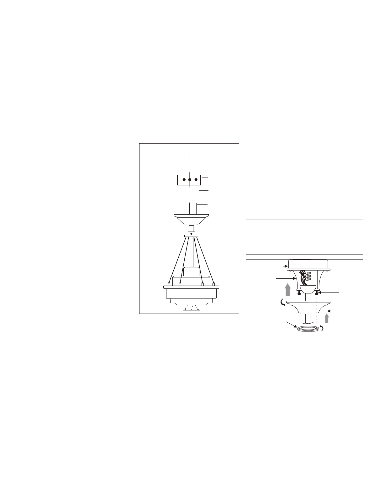
Step 1. Remove the decorative canopy bottom
cover from the canopy by turning the cover counter
clockwise. (Fig.4)
Step 2. Remove the hanger bracket from the
canopy by loosening the two screws on the bottom
of the hanging bracket a half turn from the screw
head and turning the canopy counter clockwise.
(Fig. 4)
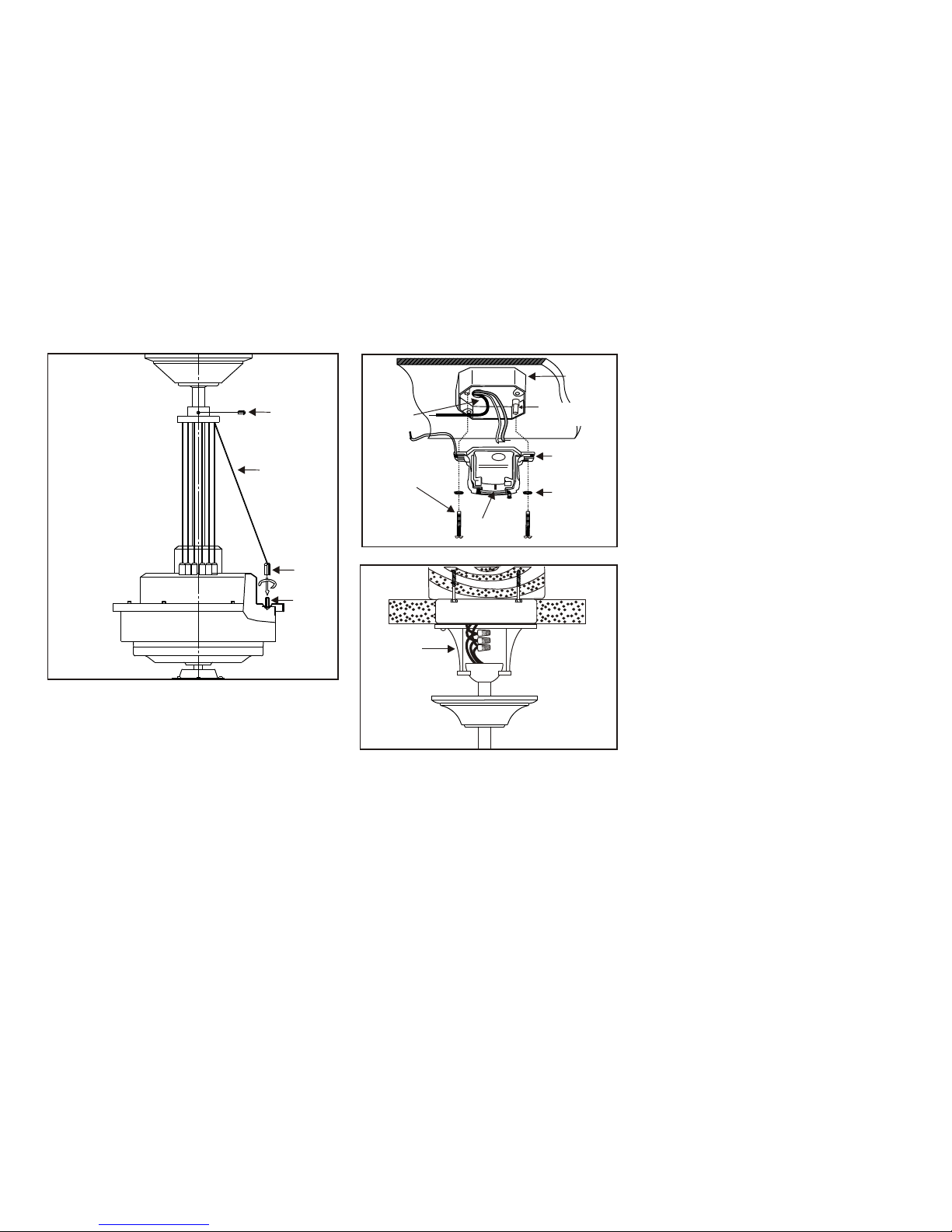
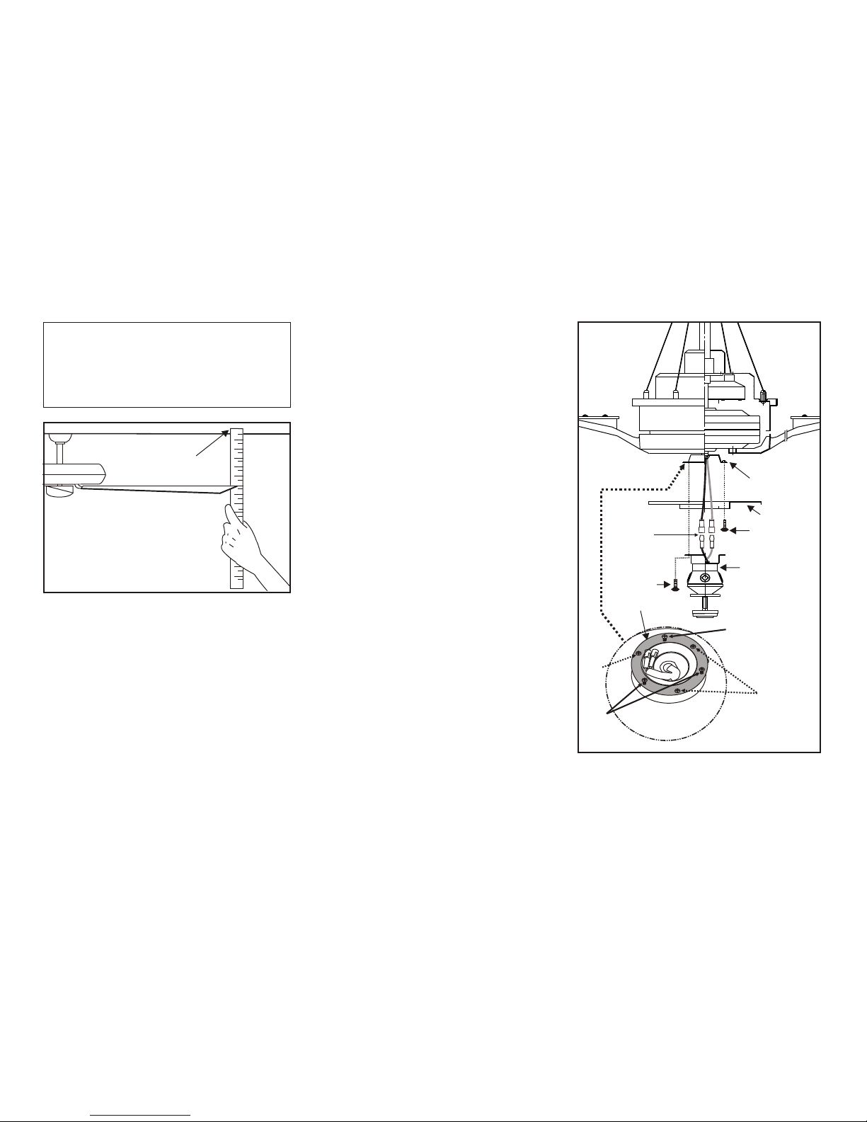
Step 3. Remove the hanger pin, lock pin and
setscrews from the top of the motor assembly. (Fig.
5)
Step 4. Loosen the setscrew from the coupling
located at the top of the decorative cable wire
assembly.
Step 5. Route wires exiting from the top of the fan
motor through the collar cover, decorative cable
wire assembly, canopy cover, canopy and then
through the ball/downrod. (Fig. 5)
Step 6. Place the nut at the end of the decorative
cable wire to the screw on the top of the motor
housing. Tighten the nut to the screw. Repeat this
procedure for the remaining decorative cable wires.
Secure the coupling with setscrew tightly. (Fig. 6)
Step 7. Align the holes at the bottom of the
downrod with the holes in the collar on the top of
the motor housing (Fig. 5) Carefully insert the
hanger pin through the holes in the collar and
downrod. Be careful not to jam the pin against the
wiring inside the downrod. Insert the locking pin
through the hole near the end of the hanger pin
until it snaps into its locked position, as noted in
the circle inset of Fig. 5.
Step 8. Tighten two setscrews on top of the
fan motor firmly. (Fig. 5)
Hanging the Fan
REMEMBER to turn off the power. Follow
the steps below to hang your fan properly:
Step 1. Install the hanger bracket to the outlet
box; be sure to align the holes in the hanger
bracket with the post holes in the outlet box
and secure with screws and washers provided
by the outlet box. (Figure 7 )
Step 2. Hanging the assembled fan onto the
mounting bracket, place the downrod ball
into the mounting bracket. Rotate the fan
until the slot of the downrod ball locks into
the tab of the mounting bracket. (Figure 8)
Step 3. Connecting the wires (see titled
"Making the Electrical Connections").
WARNING
FAILURETO PROPERLY INSTALL
LOCKING PINAS NOTED IN STEP 7 COULD
RESULTIN FANLOOSENING AND
POSSIBLYFALLING.
Figure 4
Ceiling
mounting
plate
Ceiling
canopy
Canopy
cover
Pin in
locked
position
Motor collar
Motor wires
Ball/downrod
assembly
Ceiling
canopy
Tighten
screws
firmly
Hanger pin
Locking pin Collar cover
Canopy
cover
Coupling
Decorative cable wire
assembly
Figure 5
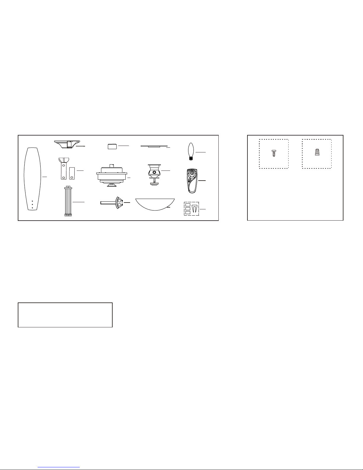
CAUTION
Remove the 3 screws from the motor
support plate, discard the 3 screws and
motor support plate.