manuals.online logo
Brands
  1. Home
  2. •
  3. Brands
  4. •
  5. Z Microsystems
  6. •
  7. Monitor
  8. •
  9. Z Microsystems 14 User manual

Z Microsystems 14 User manual

Doc# 27-0001UM Issued 7/99 Rev. 1.2
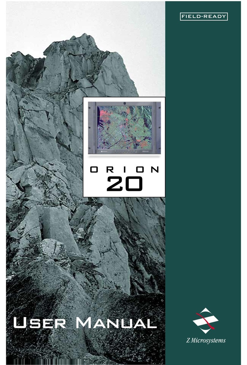
Z Microsystems
COMMAND
CONSOLE
14
User Manual
FIELD-READY
Doc# 27-0001UM Issued 7/99 Rev. 1.2
1. Use the power and
video cab es supp ied
with the Command
Conso e to he p
prevent interference
with radio and
te evision reception.
The use of cab es
and adapters may
cause interference
with e ectronic
equipment in the
vicinity of this unit.
2. This equipment has
been tested and
found to comp y with
the imits for C ass
A digita devices,
pursuant to certain
imits imposed by
Part 15 of the FCC
ru es. These imits are designed to provide
reasonab e protection against harmfu
interference in when equipment is operated in
commercia
environments. This
equipment generates,
uses and can radiate
radio frequency
energy, and, if not
insta ed and used in
accordance with the
instruction manua ,
may cause harmfu
interference to radio
communications.
3. Operation of this
equipment in a
residentia area is
ike y to cause
interference in which
case the user wi be
required to correct the
interference at his
own expense.
Changes or modifications not express y
approved by Z Microsystems cou d void
users authority to operate the equipment
FCC INFORMATION
Regulatory
2
COMMAND
CONSOLE
14
Doc# 27-0001UM Issued 7/99 Rev. 1.2
STARTING POINT 4
Shipment Contents 4
User Manua 4
System Requirements 4
Product Description 5
PREPARATION 6
INSTALL RAILS 7
INSTALL CONSOLE 8
FINAL ADJUSTMENTS 9
CABLES 9
SETUP 11
C osing Conso e 12
OPERATION 13
MONITOR ADJUSTMENTS 14
REFERENCE 18
TROUBLESHOOTING 20
SPECIFICATIONS 22
APPENDICES 23
SUPPORT 24
Further He p 24
Rep acing Parts 25
Providing Feedback 25
Y2K Comp iance 26
DRAWINGS 27
HARDWARE INSTALLATION 29
Contents
3
Doc# 27-0001UM Issued 7/99 Rev. 1.2
The User Manua comes in two
formats: printed hardcopy or CD-
ROM. This Manua is a so avai ab e
on the Z Microsystems website
(www.zmicro.com).
We recommend you read this manua
as fo ows:
Carefu y fo ow the instructions in the
Insta ation and Testing chapter for
hookup and initia contro settings.
Refer to the Operation chapter for a
comp ete description of a the user
contro s, and the Maintenance and
Troub eshooting chapters for care and
correcting any unforeseen prob ems
with the system. The Appendices and
References chapters are provided for
quick y finding technica information
about the Command Conso e.
SYSTEM REQUIREMENTS
The Command Conso e works with
any computer system that provides
industry standard screen formats from
640 x 480 to 1024 x 768, with up to
75 Hz vertica sync. See the Specifica-
tions Tab e of this Manua for a
comp ete isting of a reso utions
supported.
The Command Conso e requires a
computer with a suitab e onboard
subsystems for Video Adapter Card
that can support XGA 1024 x 768,
SVGA 800 x 600, or VGA 640 x 480
at 60 Hz
The Command Conso e shipping box
contains the fo owing:
 The Command Conso e Unit
 Video Signa Cab e
 AC/DC Power Supp y Brick with
attached DC cab e
 AC Power Cab e
 Setup Diskette
 User Manua
Remember to save your origina
shipping container and packing
materia to transport or ship the
Command Conso e.
SHIPMENT CONTENTS
4
Doc# 27-0001UM Issued 7/99 Rev. 1.2
PRODUCT DESCRIPTION
The Command
Conso e provides
a iquid crysta
disp ay, a desk
work surface and
storage for any
size keyboard
and mouse in a
3.5" high (2U)
standard 19"
rack or transit
case.
Specia y de-
signed ocks on
each side of the
Command
Conso e ho d the
compact fo ded
unit secure y in
p ace during
storage.
Re ease of the
two Z-Locks on
the front sides of
the Conso e
a ow it to s ide
out and the LCD
disp ay to quick y
swing up into a
reading position
By ifting up the
desktop, the
keyboard and
mouse can be
easi y removed
and set on top.
The ightweight and durab e a umi-
num construction provides exceptiona
strength in fie d app ications.
The high qua ity LCD screen provides
fu co or and features up to 1024 x
768 pixe reso ution.
The LCD screen has a back ight
contro that reduces power and
extends the ife of the monitor.
The side-viewing ang e is up to 160
degrees. It can be easi y adjusted to
any vertica -viewing ang e up to 100
degrees. The disp ay works effective y
with any workstation.
An e ectrostatica y-app ied and
baked-on finish is used for extreme
durabi ity for shipboard, airborne,
fie d dep oyments, and industria or
ab app ications where weight and
size are very critica .
5
Doc# 27-0001UM Issued 7/99 Rev. 1.2
TOOLS REQUIRED
PRECAUTIONS
Required Too s and Equipment
 F athead screwdriver with about 10"
shaft.
 Phi ips screwdriver with about 10"
shaft.
 Computer Setup Diskette
In preparation to insta the Com-
mand Conso e, take the fo owing
precautionary steps:
Turn off the e ectrica power to your
computer.
Verify the Command Conso e power
switch is off. If the Conso e is off, the
ight wi not be i uminated.
DANGER: To avoid shock hazard:
 Do not remove the covers around
the Command Console.
 Do not connect or disconnect the
Command Console during an
electrical storm.
 The power cord plug must be
connected to a properly wired
and grounded power outlet.
 Any equipment to which the
Command Console will be
attached must also be connected
to properly wired and grounded
power outlets.
OTE: For the fastest and easiest
installation of the
Command Console, follow
these steps in the sequence
they are presented.
Starting Point
6
Doc# 27-0001UM Issued 7/99 Rev. 1.2
SLIDE REMOVAL
With the Conso e sitting
on a workbench with the
front facing towards
you, press down to
re ease the Z-Locks on
each side of the front of
the Conso e to s ide the
side rai s back.
The s ide rai wi reach
a stop about ha f way
back.
This is a safety stop to
prevent the Conso e
s iding out too far whi e
mounted to the rack.
Simu taneous y press in
the safety catches on
each s ide rai and s ide
the side rai s a the way
off the back of the
Conso e.
The s ides shou d now
be separated from the
Conso e.
Each s ide unit inc udes
the s ide rai , with the
front Z- ock mount and
the rear mount.
On the front of the
cabinet frame, use three
Phi ips screws ((V) see
page 30 - Insta
hardware ) on each side
to secure the right and
eft Z-Lock mounts.
DO NOT tighten these
screws to a ow for
adjustment of the
Conso e within the
cabinet frame.
On the rear of the
cabinet frame, use the
three Phi ips screws ((W)
see page 30 - Insta
hardware) to oose y
secure the right and eft
rear s ide mount to the
cabinet frame.
DO NOT tighten these
screws fu y at this time.
On the s ide rai s, using
a s ot screwdriver,
oosen off the s ide
extension rai screw ((U)
see page 30 - Insta
hardware ). Repeat on
each side.
INSTALL THE SLIDES IN THE CABINET FRAME
Install Rails
7
Doc# 27-0001UM Issued 7/99 Rev. 1.2
Install Rails
Go back on the rear of
the cabinet frame, and
fu y tighten the three
Phi ips screws ((W) see
page 30 - Insta
hardware) ho ding the
s ide extension rai to
the cabinet frame.
Make sure you ho d the
s ide mounts hard
against the rack rai .
8
Doc# 27-0001UM Issued 7/99 Rev. 1.2
INSTALL THE COMMAND CONSOLE IN THE SLIDES
Pu the two Conso e
s ides out unti they ock.
Ho d the Conso e by
each side, with the front
toward you.
Feed the four cab es
coming out of the
Conso e back through
the cabinet frame.
Guide the Conso e into
the s ides and s ide the
Conso e in unti it stops.
Simu taneous y press in
the catches on each
s ide and s ide the
Conso e a the way into
the cabinet frame.
The Conso e shou d
s ide in and out easi y.
S ide the Conso e in
and out severa times.
The Conso e shou d
easi y c ose comp ete y.
To be sure the s ide and
mount assemb y are
a igned proper y, s ide
the Conso e in and out
severa times.
If the Conso e binds
during s iding, do the
fo owing:
Because of variances in
cabinet frames, there
may need to be some
adjustments of the
Conso e s ide system for
best fit and movement
of the Conso e in and
out.
TEST INSTALLATION AND MAKE ADJUSTMENTS
Install Console
9
Doc# 27-0001UM Issued 7/99 Rev. 1.2
Loosen the screws on
each of the front Z-Lock
mounts.
FINAL ADJUSTMENTS OF THE COMMAND CONSOLE
S ide the Conso e
partia y out.
Use a f athead screw
driver to s ight y move
the Z-Locks out away
from the Conso e.
Tighten a the screws on
the front Z-Lock mounts.
S ide the Conso e in and
out to see if it moves
smooth y.
Go back to the rear of
the rack and fu y
tighten the s ide
extension rai screw ((U)
see page 30 - Insta
hardware ).screws.
Note: A wrench may be
necessary to hold the
nut on the other side.
Install Console
10
Doc# 27-0001UM Issued 7/99 Rev. 1.2
C ose the storage tray
top, then p ace the
keyboard and mouse on
top of the tray door.
Using both hands,
gent y ift the Conso e
screen by the top bar.
Open the storage tray
top.
Remove the keyboard
and mouse.
A ign the Keyboard and
Mouse cab e to pass
through the recessed
access notch.
With both hands, press
both the Z-Locks down
and
SETTING UP THE MONITOR KEYBOARD AND MOUSE
S ide the Conso e a
the way out.
The storage tray door
now becomes a
workstation for the
keyboard and mouse.
There shou d be amp e
cab e to both units for
movement around the
workstation.
Setup
11
Doc# 27-0001UM Issued 7/99 Rev. 1.2
P ace the keyboard and
mouse inside the tray
a ong with a cab es
and c ose door.
Using both hands,
gent y drop the Conso e
screen by the top bar
unti it ays f at.
Remove the keyboard
and mouse from top.
Open the storage tray
top.
Press both the Z-Locks
down and s ide in the
conso e unti you hear
the positive c ick from
the ock.
CLOSING DOWN THE MONITOR
S ide the Conso e in
with both hands.
Closing Console
12
Doc# 27-0001UM Issued 7/99 Rev. 1.2
Operation
Switch the Conso e
monitor on by pushing
and re easing the power
switch marked.
Turn on the monitor and
then the computer.
13
Doc# 27-0001UM Issued 7/99 Rev. 1.2
Monitor Adjustments
The LCD monitor features an On-
Screen Display (OSD) with menus
designed to make adjusting the
monitor disp ay settings easier. When
high ighted, the icons i ustrate the
contro function to assist in identifying
which contro needs adjustment.
Before activation of the OSD menu,
the Enter button can be used to
automatica y adjust the disp ay to the
proper size and horizonta and
vertica position. The monitor must be
set to one of the 15 factory preset
timing modes to uti ize this feature.
The OSD menu activates automati-
ca y when the Enter button on the
rear of the monitor is pressed. The
OSD remains centered on the screen
whi e the adjustments are made. Use
either the or button to move the
high ight to the contro to be se ected.
A submenu or the contro with a status
bar wi appear. From the factory
ON-SCREEN DISPLAY
preset, the status bar indicates in
which direction the adjustments are
being made. Use the or button
to adjust the contro . In addition, a
second contro icon wi appear
a owing to togg e between the two
contro s.
The contrast and brightness can a so
be adjusted by simp y pressing either
the or button.
When you have finished making
adjustments, press the button to
save the setting and exit back to the
main menu. If the buttons are eft
untouched for 15 seconds, the settings
wi be automatica y saved and
exited. Whi e in the main menu,
pressing the button wi save and
exit the OSD.
14
Doc# 27-0001UM Issued 7/99 Rev. 1.2
MENU DESCRIPTIONS
AUTO ADJUSTMENT Se ect this contro to adjust the size
and position automatica y. It takes a
maximum of 10 seconds to comp ete.
This contro a ows adjustments to the
b ack eve of the disp ay screen.
Se ection of this contro a ows making
adjustments to the uminosity eve of
the disp ay screen.
Use this contro and then use the
and buttons to center the image
horizonta y on the screen.
Se ect this contro and then use the
and buttons to center the image
vertica y on the screen.
Se ect these contro s, then use the
and buttons unti the screen
images ooks focused, crisp and
sharp.
OTE: This item must operate on
full screen image. If it does
not, it is possible to operate
abnormally.
CONTRAST
BRIGHTNESS
H-POSITION
(HORIZONTAL POSITION)
V-POSITION
(VERTICAL POSITION)
TUNING & FINE TUNING
Monitor Adjustments
15
Doc# 27-0001UM Issued 7/99 Rev. 1.2
Monitor Adjustments
MENU DESCRIPTIONS
H-SIZE Se ect this contro , then use the
and buttons to expand or
decrease the image width to horizon-
ta y fi the disp ay screen.
Se ect this contro , then use the
and buttons to choose from:
Eng ish, German (Deutsch), Spanish
(Espano ), Ita ian (Ita iano) or French
(Francais).
Se ect this contro , then use the
and buttons to individua y adjust
R, G or B co or.
Se ect this contro , then use the
and buttons, which a ows
adjustment of the natura co or tone.
Se ect this contro , then use the ENTER
button to se ect in which direction
to move the OSD menu. Use the
and buttons to move the OSD
menu.
This function requires the 3.5 diskette
provided with the Command Conso e.
When the Auto Ca ibration program
diskette is used, se ect this menu using
the ENTER button , then use the
and buttons to the setting ON.
When the 640x480 or 720x400
disp ays are disp ayed, se ect this
menu using the ENTER button, then
use the and buttons to set
ON or OFF.
If the menu is operated, then the
current modes settings are a erased
and returned to the factory settings.
LANGUAGE
COLOR CONTROL
GAMMA
MOVE OSD
AUTO CALIBRATION
CALIBRATION
VGA GRAPHICS
RECALL
16
Doc# 27-0001UM Issued 7/99 Rev. 1.2
AUTO CALIBRATION PROGRAM
This program cooperates with FPMC
firmware which automatica y adjusts
and saves the pane settings, which
wi fit each support mode. It takes
about 50 seconds for auto adjust-
ment.
Fo ow these steps to start the Auto
Ca ibration Program:
1. Insert the Auto Ca ibration diskette
into the 3.5 disk driver.
2. Drag the Auto Ca ibration fi e to
the Windows background on the
computer.
3. Set ON the Auto Ca ibration in
the OSD menu.
4. Se ect taskbar properties with Auto
Hide in the Windows OS.
5. Doub e c ick the Auto Ca ibration
icon in the background.
OTE: In order to make it work
correctly, first set O  in
the OSD menu of the AUTO
CALIBRATIO item.
Monitor Adjustments
17
Doc# 27-0001UM Issued 7/99 Rev. 1.2
Reference
LED INDICATOR
The Power Management feature of the
LCD monitor is comprised of three
stages:
1. On (green)
2. Standby, Suspend or Active Off
(amber/green)
3. Out of Range (amber)
TIMING GUIDE The monitor is a mu ti-frequency
monitor. It operates at horizonta
frequencies between 31.25KHz and
60.24KHZ, vertica frequencies
between 56Hz and 75Hz. Because of
its microprocessor-based design, it
offers auto-synchronization and auto-
sizing capabi ities. The monitor offers
15 pre-programmed settings that are
isted in the fo owing tab e.
These preset modes cover most of the
common video modes supported by
popu ar graphics adapters. However,
each adapters imp ementation of
these video modes may vary s ight y in
timing. If it is necessary to make
minor disp ay adjustments (horizonta
and vertica position and horizonta
position), refer to the On-Screen
Disp ay section of this manua for
instructions.
18
Doc# 27-0001UM Issued 7/99 Rev. 1.2
TIMING GUIDE
The monitor is not imited to these
preset factory-timing modes. In fact,
because the monitor is mu ti-scan-
ning, it can accept any signa within its
frequency range of 31.25KHz -
60.24KHz horizonta and 56Hz -
75Hz vertica .
If it is desired to use one of the preset
timing modes, refer to the video card
manufacturers insta ation guide for
instructions on how to make these
changes. The video card contro s the
refresh rate. Most video cards provide
software uti ity or hardware DIP
switches that a ow to change the
frequency used for each reso ution.
* If using Macintosh, need Mac adapter.
Reference
19
Doc# 27-0001UM Issued 7/99 Rev. 1.2
Troubleshooting
NO POWER  F ip the Power switch ON. The
Power LED turns on.
 Make sure the A/C power cord is
secure y connected to the power
jack and to a power out et.
 P ug another e ectrica device ( ike
a radio) into the power out et to
verify that the power out et is
supp ying the proper vo tage.
 Make sure the video cab e attached
from the monitor is tight y secured
to the video output port on the back
of the computer.
 Adjust the brightness and contrast.
 Not enough power is being
supp ied to the LCD monitor.
Connect the LCD monitor to a
different out et. If a surge protector
is being used, there may be too
many devices p ugged in.
 See Timing Guide Section of this
manua with a ist of refresh rates
and frequency settings showing the
recommended setting for the LCD
monitor.
 If any co ors (red, green or b ue)
are missing, check the video cab e
to make sure it is secure y con-
nected. Loose pins in the cab e
connector cou d cause a bad
connection.
 Connect the LCD monitor to
another computer.
 Check the graphics card for proper
sync scheme (or sync po arities) to
match the LCD monitors specifica-
tions.
POWER ON BUT NO SCREEN
IMAGE
FLICKERING
WRONG OR ABNORMAL COLORS
20

This manual suits for next models

1

Other Z Microsystems Monitor manuals

Z Microsystems GLIDER 20 User manual

Z Microsystems

Z Microsystems GLIDER 20 User manual

Z Microsystems StarGate 20 User manual

Z Microsystems

Z Microsystems StarGate 20 User manual

Z Microsystems Glider 21 User manual

Z Microsystems

Z Microsystems Glider 21 User manual

Z Microsystems GCS17T User manual

Z Microsystems

Z Microsystems GCS17T User manual

Z Microsystems 18 User manual

Z Microsystems

Z Microsystems 18 User manual

Z Microsystems GLIDER 20 User manual

Z Microsystems

Z Microsystems GLIDER 20 User manual

Z Microsystems Orion 20 User manual

Z Microsystems

Z Microsystems Orion 20 User manual

Popular Monitor manuals by other brands

LG 47WX50MF-B Speci?cations

LG

LG 47WX50MF-B Speci?cations

Barco SLite 10 XP Brochure & specs

Barco

Barco SLite 10 XP Brochure & specs

Lenovo D222 user guide

Lenovo

Lenovo D222 user guide

AOC 619Fh Specification sheet

AOC

AOC 619Fh Specification sheet

JVC DT-V17L3R instructions

JVC

JVC DT-V17L3R instructions

Philips 105S51 Specifications

Philips

Philips 105S51 Specifications

Itek ITMF24T061FHD user manual

Itek

Itek ITMF24T061FHD user manual

Daktronics Galaxy AF-3400 Series DISPLAY MANUAL

Daktronics

Daktronics Galaxy AF-3400 Series DISPLAY MANUAL

AOC 831S Specifications

AOC

AOC 831S Specifications

AOC 712Swa-1 user manual

AOC

AOC 712Swa-1 user manual

Fujitsu Plasmavision PDS4208W-B user manual

Fujitsu

Fujitsu Plasmavision PDS4208W-B user manual

LG 55MH5K owner's manual

LG

LG 55MH5K owner's manual

Effinet Systems EFG-2902F Service manual

Effinet Systems

Effinet Systems EFG-2902F Service manual

PSI Displays SDI Series user manual

PSI Displays

PSI Displays SDI Series user manual

Eizo FlexScan T965 Specifications

Eizo

Eizo FlexScan T965 Specifications

LG Flatron L1510BF Service manual

LG

LG Flatron L1510BF Service manual

Samsung U28R55 Series user manual

Samsung

Samsung U28R55 Series user manual

DAEWOO ELECTRONICS 712D Service manual

DAEWOO ELECTRONICS

DAEWOO ELECTRONICS 712D Service manual

manuals.online logo
manuals.online logoBrands
  • About & Mission
  • Contact us
  • Privacy Policy
  • Terms and Conditions

Copyright 2025 Manuals.Online. All Rights Reserved.