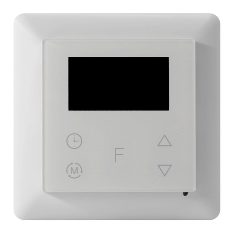
Z-Wave 5430499 User manual

Ver 2016-A
·STANDARD COLOR White RAL 9003 – Black RAL 9011
·APPROVALS CE – Z-Wave Plus
IMPORTANT!
PLEASE READ THIS BEFORE INSTALLATION.
This thermostat is tested and certified by Pepper One Gmbh
according to the requirements put forward by the Z-Wave
Alliance. This is a Z-Wave Plus product with the 500 series chip.
If the product does not work with your gateway, then the
gateway manufacturer has not made an integration or
implemented such a thermostat with their gateway. We do not
give any guarantee towards integration.
PRINCIPLES FOR REGULATION
The Heatit Z-Wave is designed for controlling electrical heating
cables and electrical radiators/convectors. The thermostat
has 2 internal temperature sensors and has 3 algorithms for
temperature compensation.
After you have set the temperature, the thermostat will use
a hysteresis to regulate the temperature. The hysteresis is
adjustable.
TEMPERATURE SHOWN IN DISPLAY
The temperature shown in the display is the actual temperature
for floor sensor and the external room sensor. You are able to
calibrate the sensor values.
When using the internal room sensor, the temperature shown is
the set point. Due to the internal heat buildup in the thermostat,
we do not recommend to use this function. This makes the
thermostat sensitive towards draft in the connection box.
If the thermostat is to be used with waterbased heating systems,
you have to use an external sensor.
Z-WAVE THERMOSTAT – SETUP
This manual describes the most essential functions and
technical specifications of the thermostat.
These instructions help the user to control the thermostat, and
the electrician to install and setup the thermostat.
INSTALLATION
Installation must be done by a qualified Electrical Installer in
accordance with the National Building codes. Before installation,
disconnect any power to the thermostat’s mains. During
installation of the thermostat, power to the thermostat must be
disconnected AT ALL TIMES!
Use e.g. a small slotted screwdriver. The front cover and the
frame can now be removed.
Now connect the wires to the thermostat’s terminals:
HEATING (N) Heating cable connection (Neutral)
N Power connection (Neutral) 230V
L Power connection (Live) 230V
HEATING (L) Heating cable connection (Live)
PILOT 230V pilot signal
FLOOR SENSOR NTC type (10, 12, 15, 33 or 47kΩ). Default 10kΩ.
EXTERNAL SENSOR NTC type (10, 12, 15, 33 or 47kΩ). Default 10kΩ.
Next, position the thermostat and fasten it onto the wall’s
mounting box using 2-4 screws. Position the frame, then
position and carefully press the front cover until it snaps in
place. Check that the front cover has snapped in place properly
on both left and right side. The front cover should now be firmly
fixed on all sides.
·DISPLAY LED-display 3x 7-Seg 13.2mm CA white
STARTUP
AFTER CONNECTING THE POWER TO THE THERMOSTAT FOR THE
FIRST TIME, ALL PARAMETERS WILL DEFAULT SETTINGS.
2 yr
HEATIT Z-WAVE
Installation guide
SW 1.7
Made in EU
TF 021
HEATING L
L
N
HEATING N
PILOTWIRE
FLOOR
SENSOR
EXTERNAL
SENSOR
Mål på Z-wave-logo: 10mm x 8mm
01.01.2016

CONTROL
The thermostat is controlled by three touch sensitive capacitive
buttons.
You only need to touch lightly to activate the buttons.
• Left (Up)
• Center (Confirm)
• Right (Down)
INCLUSION/EXCLUSION
To include the thermostat to your home automation gateway,
press Center (confirm) for 10 seconds.
The display will show OFF. Press Right (down) 4 times till you see
Con in the display.
Now start add device in your home automation software.
Start inclusion mode by pressing Center (confirm) for
approximately 2 seconds. The inclusion/exclusion icon will
appear in the display.
Confirmation will show Inc/EcL in the display.
If inclusion fails, Err (error) will appear.
Leave programming mode by choosing ESC in menu. Your
thermostat is ready for use with default settings.
PROGRAMMING YOUR THERMOSTAT
To activate the programming mode, press Center (confirm) for
10 seconds. Now the display will show OFF.
Now you are in programming mode. To scroll up and down
in the menu use button 1 and 3 (left and right) to navigate. To
enter submenu press Center (confirm). Always confirm your
setting by pressing Center (confirm) for 2 seconds.
Menu:
OFF Turns the thermostat off.
ASensors:
A Air/room sensor
AF Air+Floor sensor
A2 External room sensor
A2F External room sensor + Floor sensor
P Power regulator
FP Floor sensor + Power regulator
F Floor sensor
SEnSelect the right Ohm value for your external/floor sensor.
NTC type (10, 12, 15, 33 or 47kΩ). Default 10kΩ.
CAE Calibration for external sensor.
CAF Calibration for floor sensor.
CAR Calibration for room sensor.
br1 Brightness of display can be adjusted in this menu.
Con Activation of inclusion/exclusion mode.
diF Hysteresis
ALoSetting lowest allowed temperature (limitation).
(Airsensor)
AHI Setting highest allowed temperature (limitation).
(Airsensor)
FLO Setting lowest allowed temperature (limitation).
(Florsensor)
FHI Setting highest allowed temperature (limitation).
(Floorsensor)
ESC Escape – go out of programming menu.
PRODUCT INFO Heatit Z-Wave
TECHNICAL DATA
Rated voltage: 230V 50/60Hz
Max load: 3600W (resistive load)
750W self-limiting heating cable
Max current: 16A
Power consumption: 1,5W
Power regulator: Time cycle 0-30min
Min/max installation temp: -20°C to 40°C
Min/max operating temp: 5°C to 40°C
Temperature intervals: Floor sensor 5°C to 40°C
External room sensor 5°C to 40°C
Hysteresis: 0,3°C to 3,0°C (default 0,5°C)
Sensor values: 0°C 29,1 kOhm
10°C 18,6 kOhm
15°C 15,1 kOhm
20°C 12,2 kOhm
25°C 10,0 kOhm
Switch: Single-pole switch
IP class: IP21
TERMINAL
Use 1,5mm² or 2,5mm² according to load.
INCLUDED IN PACKAGE
Floor sensor 3 meters, Art. no. 5430109
WARRANTY
2 years
The thermostat is designed for electrical heating.
Thermo-Floor AS tar forbehold om typografiske feil,
andre feil eller mangler i vår informasjon.
Alle elektriske installasjoner skal
utføres av autorisert installatør.
Produktet skal installeres og dokumernteres ihht
gjeldende utgave av NEK 400 og
installasjonsveiledning.
FEATURES
· Floor sensor
· External room sensor
· Temperature limiter
· Power regulator
· Z-Wave Plus chip, 500 series
· Weekly program
· Setback mode via gateway
or pilot wire
· 7-segment LCD-screen
· Can be used in connection
with different NTC-sensors
· Lock mode/child lock
· Backlight
· Calibration
· 8 associations
ART. NO. PRODUCT COLOR
5430499 Heatit Z-Wave thermostat 3600W 16A White RAL 9003
5430498 Heatit Z-Wave thermostat 3600W 16A Black RAL 9011
5430311 Frame for Heatit White RAL 9003
5430312 Frame for Heatit Black RAL 9011
5430497 Cable for software update on thermostat
5430108 Floor sensor Ø3mm 6m NTC 10 kOhm
5430109 Floor sensor Ø4mm 3m NTC 10 kOhm
5430128 External room sensor NTC 10 kOhm
5430129 External room sensor, mini, NTC 10 kOhm
Thermo-Floor AS l Østre Totenvei 24, NO-2816 Gjøvik, NORWAY

CHOICE OF SENSOR
The thermostat has a range of choices when it comes to
sensors. To get to the menu you have to press Center (confirm)
for 10 seconds, then press Right (down) once and an A shows
in the display. Then press Center (confirm) again and you can
choose one of these modes, while moving up and down with
buttons Left or Right.
AAir/room sensor
AF Air+Floor sensor
A2 External room sensor
A2F External room sensor + Floor sensor
PPower regulator
FP Floor sensor + Power regulator
FFloor sensor
When you have decided on the sensor mode you want to use,
press Center (confirm) button.
If you choose F or AF and there is no floor sensor installed, Err
will display in the screen.
SELECT THE RIGHT OHM VALUE FOR YOUR EXTERNAL/
FLOOR SENSOR
The following values are available: NTC type (10, 12, 15, 33 or
47kΩ). Default 10kΩ. The function is only active when an external
sensor is connected. Confirm with Center (confirm) button.
CALIBRATION
In this mode you are able to adjust the displayed temperature.
If the thermostat of some reason (or sensor) is not calibrated
properly you are able to make minor changes to the
temperature. You are able to raise/lower the set point by up to
4°C. Confirm with Center (confirm) button.
This function is only available for the floor sensor and external
room sensor.
BRIGHTNESS
Use Left and Right (up and down) button to adjust the
brightness between 0-9. Confirm with Center (confirm) button.
INCLUSION/EXCLUSION
To include the thermostat to your home automation gateway,
press Center (confirm) button for 10 seconds.
The display will show OFF. Press Right (down) 4 times till you see
Con in the display.
Now start add device in your home automation software.
Start inclusion mode by pressing Center (confirm) button for
approximately 2 seconds. The inclusion/exclusion icon will
appear in the display.
Confirmation will show Inc/EcL in the display.
If inclusion fails, Err (error) will appear.
HYSTERESIS (DIF)
In this mode you are able to make changes to the hysteresis in
the thermostat. This means that you can changes the hysteresis
from 0.2°C up to max 3.0°C. Confirm with Center (confirm)
button. Default setting is 0.5°C. When using a waterbased
system the hysteresis should be min 1.0°C.
Min/Max temperature settings
FLO – Min Floor temperature
FHI – Max Floor temperature
ALO – Min Air/room temperature
AHI – Max Air/room temperature
PLO – Min temperature in Power Reg Mode
Confirm with Center (confirm).
ESC
Leaving programming mode. Confirm with Center (confirm)
button.
STANDBY AND MAIN SCREEN
When the thermostat remains untouched for a while, it will
automatically go to standby screen. In standby screen the light
is dimmed. By pressing Left or Right (up or down) button the
set point will be shown in the display.
DISPLAY ON/OFF - DON/DOF
Activate by pressing Left and Center (up and confirm) button for
10 seconds.
In case doF is activated, the screen will be blank (can be used if
installed where people are sensitive to the light of the display).
A very nice feature when used in a bedroom. When touching
the display, the screen lights up.
CHILDLOCK - LOC
By pressing Left and Right (up and down) buttons for 10
seconds, child lock will be activated and no changes can be
made. Trying to make changes causes the LOC text to appear
in the display. Child lock is deactivated by pressing Left and
Right (up and down) buttons for 10 seconds. OPn will appear
in the display.
FACTORY RESET - RES
By pressing buttons Right and Center (down and confirm) for 20
seconds, the thermostat will perform a complete factory reset.
NB! Please use this procedure only when the primary controller/
gateway is missing or otherwise inoperable.
CO/ECO MODE
The thermostat has 2 main programs, CO – comfort mode and
ECO - economy mode. When Center (confirm) button is pushed
for 2 seconds you switch between the 2 modes. You would
normally have 2 different set-points for the different modes.
CO – mode: Is used for normal use. Example: 22°C.
ECO – mode: Is a setback mode that you can use if the
thermostat is installed in a room or a house that is rarely used.
The ECO-mode can also be activated by the pilot wire if this
is connected.
Some gateways also support switching between CO/ECO
mode. We would normally think about CO/ECO as functions
for Home/Away.
ASSOCIATIONS
Association enables the thermostat to control a device e.g a
relay or a wallplug, that is included in your z-wave network.
With this function the thermostat can control other heating
devices such as an electric radiator or an electric fan. Remember
to use association group 2, when you enable the associations.
Maximum 8 devices per thermostat.
NOTE Wooden floor requires that the use of a max temperature
floor sensor is connected. The floor temperature should be
limited to 27°C.
In order to run some schedule or week program, the primary
controller/gateway should be responsible for controlling the
thermostat using those selected command classes.
Classes:
GENERIC_TYPE_THERMOSTAT
SPECIFIC_TYPE_SETPOINT_THERMOSTAT
COMMAND_CLASS_BASIC
COMMAND_CLASS_THERMOSTAT_SETPOINT_V3
COMMAND_CLASS_THERMOSTAT_SETBACK
COMMAND_CLASS_SENSOR_MULTILEVEL
COMMAND_CLASS_VERSION
COMMAND_CLASS_MANUFACTURER_SPECIFIC
COMMAND_CLASS_ASSOCIATION
+ All other mandatory classes for selected device type
DESCRIPTION
Temperature range +5°C/+40°C
Displayed temperature -30°C 60°C
Floor min. limit 5°C (5°C 35°C)
Floor max. limit 35°C (5°C 35°C)
Air min. limit 5°C (5°C 40°C)
Air max. limit 35°C (5°C 40°C)
Regulator min. limit 0 (0 9)
Hysteresis 0,3°C - 3,0°C
Default hysteresis 0,5°C
CO set point 21°C (5°C 40°C)
ECO set point 18°C (5°C 40°C)
Power regulator P02 (P00 P10) cycle of 30 minutes
Temperature setback Adjustable within temperature range
Temperature setback activation Pilot wire/Z-Wave user interface
Thermo-Floor AS can
not be held liable for
typographical errors, other
errors or omittances in
our information.
Product specifications
may change without
further notice.
All electrical installations
must be carried out by a
licensed electrician.
The product must be installed
in accordance with national
building codes and our
installation guides.
Thermo-Floor AS l Østre Totenvei 24, NO-2816 Gjøvik, NORWAY
This manual suits for next models
1
Table of contents
Other Z-Wave Thermostat manuals

Z-Wave
Z-Wave SR-ZV9092A User manual

Z-Wave
Z-Wave LinkedGo ST1000EZ0 User manual

Z-Wave
Z-Wave ZTS-110 Z-Thermostat User manual

Z-Wave
Z-Wave CT100 User manual

Z-Wave
Z-Wave ZTS-100 User manual

Z-Wave
Z-Wave CT100 User manual

Z-Wave
Z-Wave ZTS-500 User manual

Z-Wave
Z-Wave ZTS-110 Z-Thermostat User manual

Z-Wave
Z-Wave T100R User manual
Popular Thermostat manuals by other brands

Thermo Sphere
Thermo Sphere Dual Control Touch instruction manual

Timeguard
Timeguard TRT033N operating instructions

MCOHome
MCOHome MH4-US user manual

CORAB
CORAB TSTPHA01 installation instructions

Timeguard
Timeguard TRT036N Installation & operating instructions

Pro 1 IAQ
Pro 1 IAQ True Comfort T715 Operation manual