Z-Wave ZTS-110 Z-Thermostat User manual

ZTS-110
Z-Thermostat
USER MANUAL
Firmware Version: 2.06

Table of Contents
Introduction 2
Features list 3
Glossary 4
Physical Installation and Wiring 5
Installation Location 6
6
Wiring 7
Jumper Settings for ELECTH-HPUMP and HE-HG 9
10
10
10
11
11
12
17
18
18
20
23
23
25
26
26
Check FLiRS / Always Listening mode in ZTS-110 28
28
36
37
38
39
39
Physically Installing the Thermostat
Setup and Operations
Product Overview
Description of Function Keys
Activate/Deactivate Easy Mode
Temperature Scale selection in Easy Mode
Setting Mode
Change Mode
Change Fan Mode
Select Program Mode
Override/Permanent Override 19
Setting Schedule
Battery Low Indication
Defrost Indication
Out of Temperature Range Indication 23
Advanced Recovery Indication 24
Filter Counter 25
Short Cycle Start Up Protection
Energy Saving Mode
Z-Wave Setup and Operations
Z-Wave Add (Include) / Delete (Exclude) Mode
Support for Association Groups 30
Z-Wave Configuration Parameters 32
Reset ZTS-110 to Factory Default Settings 35
Frequently Asked Questions
Technical Specifications
Checking Accessories
FCC Notice 39
Warnings
Caution
1

ZTS-110 Z-Thermostat
Introduction
ZTS-110 Z-Thermostat (Figure 1) is a Z-Wave enabled programmable thermostat
that allows you to control your room temperature with programmable time schedule
such as WAKE, AWAY, HOME and SLEEP event which can maximize energy
conservation and comfort while minimizing the effort required to maintaining the
appropriate temperature in your home whether you are at home or away.
Also, you can use the ZTS-110 to control / check your room temperature by smart
phone or PC while you are at home or outside through Z-Wave gateway.
Figure 1. ZTS-110
2
WAKE
AM
PROG ON
MO
HEAT
FAN ON
1

Features List
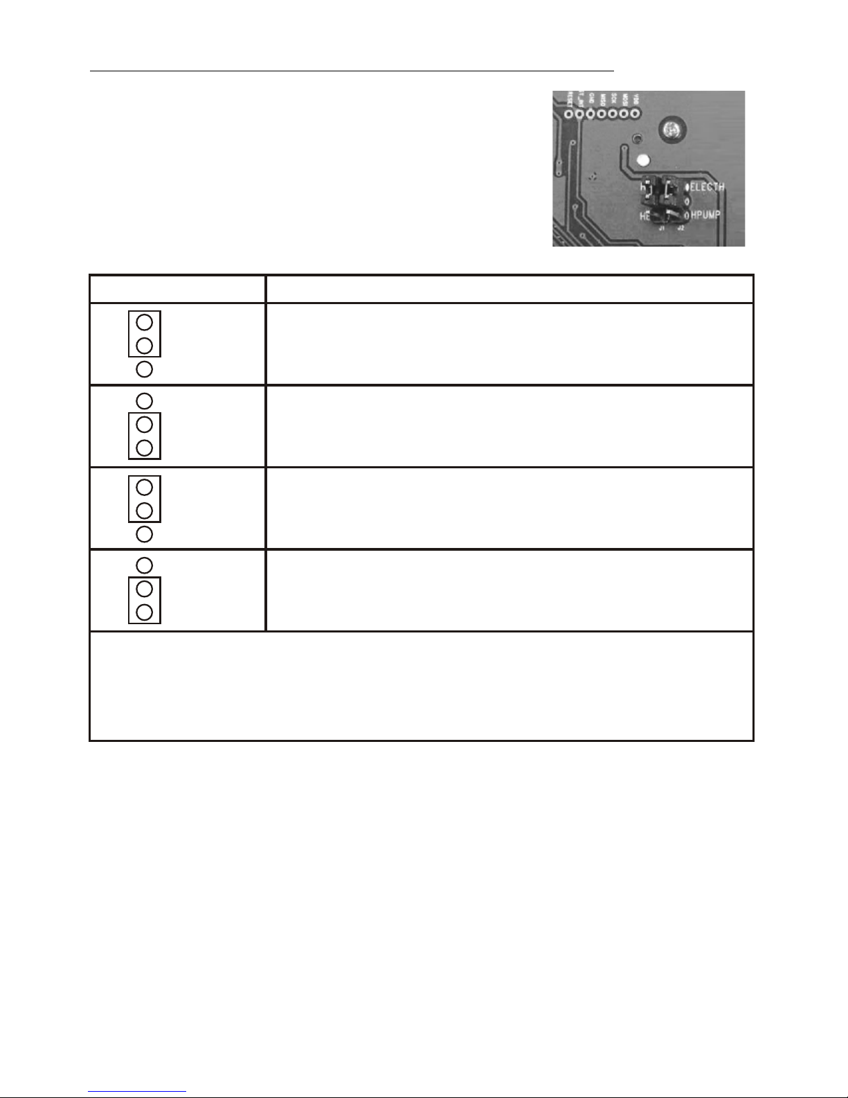
HVAC System Type Compatible:
- Standard (gas/electric) or Heat Pump
Multistage System Compatible:
- Standard HVAC Systems: 2 stage heating, 1 stage cooling
- Heat Pump Systems: 2 stage heating, 1 stage cooling
Heat Pump change over valve:
- Selectable change over with cool or with heat
Program Style:
- 2 program modes for scheduling (Mo-Fr, Sa-Su)
- 4 Separate Time and Temperature Settings for each program
- Heat and Cool set-points for each program
- Temporary Program Override
- Permanent Program Override
- Built-in flash memory stores heat and cool program settings
Temperature Display and Control:
o o
- Temperature display in F or C
o o
- Temperature Measurable Range: 32-99 F / 0-40 C
o o
- Temperature Setting Range: 41-99 F / 5-37 C
- Adjustable Temperature Control Swing/Differential
o o o o o o o o
a) Swing: 1 F, 2 F, 3 F or 4 F ( 0.5 C, 1.0 C, 1.5 C or 2 C)
o o o o o o o o
b) Differential: 1 F, 2 F, 3 F or 4 F ( 0.5 C, 1.0 C, 1.5 C or 2 C)
- Advanced Recovery Mode (ARM)
- Defrost Function
- Short cycle start up protection
Clock:
- Time display format: 12/24 hour clock selection with day displayed
Filter Counter:
- Filter change reminder displayed after 500 hours usage (500-4000hrs)
Z-Wave:
- Support Network Wide Inclusion (NWI) and Explore Frames
- Support Easy mode (disable local advanced setup and control)
- Support "Frequently Listening Routing Slaves" (FLiRS) mode and "Always Listening" mode
- Support battery level report
- Support Association Groups
a)Association Group_1 is used for Heat Pump control
b)Association Group_2 is used for Compressor control
c)Association Group_3 is used to report status change such as AUTO report to gateway
Power:
- Support AA x 4 alkaline batteries or 24Vac input
3

Glossary
Devices and nodes are all terms to describe an individual Z-Wave
device. These are all interchangeable when setting up your Z-Wave
network.
Device or Node
4
Inclusion Add a Z-Wave device to the network.
Exclusion Delete a Z-Wave device from the network.
Remove To take a device out of a group, scene or association group while that
device still exists in the same Z-Wave network.
Network Wide
Inclusion (NWI)
Network Wide Inclusion (NWI) enables both end-user friendly, Plug
and Play like Z-Wave network installation as well as professional
installation scenario where the inclusion process in terms of time will
be reduced significantly. NWI is a feature supported by a new frame
type named Explorer which enables the Z-Wave protocol to implement
Adaptive Source Routing.
Z-Wave
Network
A collection of Z-Wave devices is controlled by primary and secondary
controllers operating on the same system. A Z-Wave network has its
own unique ID code so that controllers not in the network cannot
control the system.
Primary
Controller
The first controller is used to set up your devices and network. Only
the Primary Controller can be used to include or delete devices from a
network. It is recommended that you mark the primary controller for
each network for ease in modifying your network.
FLiRS Mode
FLiRS is abbreviation for "Frequently Listening Routing Slave".
FLiRS mode is targeted for battery operated applications and will enter
sleep mode frequently in order to conserve battery consumption. The
response to Z-Wave command is not as quick as Always Listening
Device. Normally there is 1-2 seconds latency.
Always
Listening Mode
Always Listening mode is targeted for AC power operated applications
and it can act as a repeater, which will re-transmit the RF signal to
ensure that the signal is received by its intended destination by routing
the signal around obstacle and radio dead spots. The response to
Z-Wave command is immediate.
Association
Association is used to organize nodes in different groups allowing the
device to identify the nodes by a group identifier. The groups can also
be copied to other devices.

Physical Installation and Wiring
Read following scenarios carefully before you start as it matters to the
battery life under Z-Wave operation:
ZTS-110 can be powered by 4 x AAbatteries, and/or 24Vac C wire.
a) If it is powered by batteries or powered by batteries first then applied with 24Vac
before Z-Wave inclusion, ZTS-110 will self-configure to FLiRS mode which will
save battery life by sleeping.
b) If it is powered by 24Vac or powered by 24Vac first then applied with batteries
before Z-Wave inclusion, ZTS-110 will self-configure to Always Listening Mode
which will not sleep.
c) After inclusion process, ZTS-110 will not detect power source and not allow
changing operation mode. You must perform exclusion process first if need to
change Z-Wave operation mode.
d) After Z-Wave inclusion process, if you reset ZTS-110 to default while both 24Vac
and batteries are applied, ZTS-110 will take 24Vac as primary power source and
self-configure to Always Listening Mode, because reset to default process will
automatically exclude ZTS-110 from the Z-Wave network. You should disconnect
the power source and re-apply the power so ZTS-110 can detect the power
source type and self-configure to corresponding mode.
You may check Glossary for the definition of FLiRS mode and Always Listening
Mode.
CAUTION
- We highly recommend that this installation procedure is performed by a
trained HVAC technician.
- Read the enclosed instructions carefully before installing your new Z-
Thermostat. Pay close attention to all warnings and notes and carefully
follow the installation steps in the order they are presented to save time and
minimize the risk of damaging the thermostat or the system it controls.
- Turn off ZTS-110 and the electronic devices (e.g. heater, cooler) which will
be connected and the electric source before installation and maintenance.
Battery safety!
- Use new batteries of the recommended type and size only.
- Never mix used and new batteries together.
- To avoid chemical leaks, remove batteries from the ZTS-110 if you do not
intend to use the unit for an extended period of time.
- Dispose of used batteries properly; do not burn or bury them.
5

6
Installation Location
The Thermostat is restricted to be used in indoor only. It should be mounted on an
inner wall about 1.5m (5ft) above the floor at a position where it is readily affected
by changes of the general room temperature with freely circulating air. Avoid
mounting above or near hot surfaces or equipment (e.g. TV, heater, refrigerator).
Avoid mounting where it will be exposed to direct sunshine, drafts, or in a laundry
room or other enclosed space. Do not expose this unit to dripping or splashing
liquids.
Physically Installing the Thermostat
1. Open the ZTS-110 by pulling the two sections apart (Figure 2). Use the fingertips
of one hand to grip the tab on the front housing.
2. Apply power to the thermostat:
a) For battery power, install four AA batteries (alkaline recommended). Match
the polarity of the batteries with the +/- marks inside the battery compartment.
b) For 24Vac power, connect the wires as described in "Wiring"
3. Insert the two included wall anchors into the wall, aligned with two of the
mounting holes in the back housing of the thermostat.
4. Fasten the back housing to the wall using the two included mounting screws.
Insert the screws through the mounting holes in the housing and into the wall
anchors. (Figure 3)
5. Align the front housing of the thermostat with the back housing and push until the
housing sections are locked together.
Figure 3. Install the front housing
Figure 2. Open ZTS-110

7
Wiring
- Be sure the operation mode is OFF
and Fan selection is Fan Auto
- Wire the proper cables at the terminal
block according to the circuit diagram
- Afterward, push all cables back into
the wall
- Do not use metal conduit or of cable
provided with a metal sheath
- Recommends adding fuse or
protective device in the line circuit
Important!
If you will be powering the ZTS-110 with 24Vac:
Connect the "24Vac Common" (typically the black wire/terminal) and "24Vac
Power" (typically the Red wire/terminal) from the HVAC system to the ZTS-110
HVAC System terminal block "C" and "RH" or "RC" terminals (see the following
explanation, these may be jumpered together).
Common or Split Transformer Systems:
Most HVAC systems have a common heating and cooling transformer. You must
insert a jumper wire to tie the RH and RC inputs together for this configuration. If
you have a system with separate heating and cooling transformers, do not insert a
jumper wire between RC and RH.
When wiring split systems, wire the heating systems "24Vac Power" (red wire) to
the ZTS-110 "RH" terminal, and wire the cooling systems "24Vac Power" to the
ZTS-110 "RC" terminal. Also wire the cooling systems "24Vac Common" to the
ZTS-110 "C" terminals.
Note: Do not split RC/RH for Heat Pump systems!
Figure 4. Non-heat pump (Standard Gas or Electric) HVAC system wiring
Terminals
Cool changeover (heat pump)
Heat changeover (heat pump)
2nd Stage heater
1st Stage heater
Fan
Compressor
24Vac Common
24Vac Power for Cooling
24Vac Power for Heating
Symbol
O
B
W2
W1
G
Y
RC
RH
C
Standard HVACSystem
nd
W2 - 2 stage heater
st
W1 - 1 stage heater
G - Fan
Y - Compressor
R - 24VacPower
C - 24VacCommon
O
B
W2
W1
G
Y
RC
RH
C
Brown
White
Green
Yellow
Red
Black
ELECTH
HPUMP
J2

Figure 5. Heat pump HVAC system wiring
Figure 6. Non-heat pump 2-wires system wiring
Figure 7.Heat pump 2-wires system wiring
Thermostat should be powered by batteries and support heating control only.
For heat pump output, there is a 3 minutes off time for heat pump protection.
8
Heat Pump HVAC System
O - Cool changeover(heat pump)
B - Heat changeover(heat pump)
nd
W2 - 2 stage heater
G - Fan
Y - Compressor
R - 24VacPower
C - 24VacCommon
O
B
W2
W1
G
Y
RC
RH
C
Brown
Green
Yellow
Red
Black
Blue
Orange
ELECTH
HPUMP
J2
ELECTH
HPUMP
J2
Y - Compressor
R - 24VacPower
O
B
W2
W1
G
Y
RC
RH
C
Yellow
Red
HG
HE
J1
HG
HE
J1
ELECTH
HPUMP
J2
st
W1 - 1 stage heater
R - 24VacPower
O
B
W2
W1
G
Y
RC
RH
C
White
Red

9
Jumper Settings for ELECTH-HPUMP and HE-HG
There are 6 jumpered pins on the thermostat circuit
board that identify whether your system is:
- Gas or electric heater
- Non-heat pump or heat pump system
You must ensure that these pins are set correctly for
your system. The pin location is shown in the following
diagram which is located at back side of ZTS-110.
Set to HG for Gas heat-fan controlled unit (Default)
Fan will maintain off state.
Set to HE for Electrical heat-fan controlled unit
Fan will be turned on when there is heating output.
HG
HE
HG
HE
Note:
The HE and HG jumper controls the Fan when set to Auto in heating mode.
If user selects Fan ON at thermostat, the Fan will be turned on without considering the
HE-HG jumper selection.
Jumper Function Description
Set to ELECTH for non-heat pump system (Default)
- When there is a heating request, thermostat will turn on W1
- When there is a cooling request, thermostat will turn on Y
Set to HPUMP for heat pump system
- When there is a heating request, thermostat will turn on Y and B
- When there is a cooling request, thermostat will turn on Y and O
ELECTH
HPUMP
ELECTH
HPUMP

10
Setup and Operations
Product Overview
Figure 8. ZTS-110
Description of Function Keys
Event mode
Day
Time
Program mode Fan mode
Inclusion indication Battery low indication
Mode
Current temperature
WAKE
AM
PROG ON
MO
HEAT
FAN ON
1
Key Description
Symbol
Increase value / Toggle selection
Decrease value / Toggle selection
Select fan mode; also the Backward function key in some menus
Change operation mode; also the Forward function key in some
menus
Select program mode:
PROG ON, OVERRIDE and PERMANENT OVERRIDE;
also the Confirm function key in some menus
Back to Home

11
Activate/Deactivate Easy Mode
The ZTS-110 is default with Easy mode, below illustrates the functions of Easy
mode:
- Active functions: Change Mode, change Fan mode and Temperature Scale
selection
- Inactive functions: Scheduling, Program Mode, Clock Display, Setting Time,
Setting Swing, Setting, Differential Set-Point and Advanced
Recovery Mode
User can use Easy mode to disable Schedule function and the schedule will be
controlled by Z-Wave gateway. User can still change temperature and mode by
pressing the local physical buttons.
User can deactivate the Easy mode by local "Setting Mode" or Z-Wave
Configuration Parameter number 8. (Please refer to Z-Wave Configuration
parameters table).
Below is the example by local setting:
Temperature Scale selection in Easy Mode
LCD indicationProcedure / Description
Press and hold "Mode" key for 2 seconds to
entry the setting mode.
It will display "EASY YES" if it stays in
Easy mode. Otherwise, it will display "EASY no"
if Easy mode is deactivated.
Press Up/Down key to toggle the selection.
Press "Prog" key to confirm your settings.
- it will go back to Home page if selected "YES".
- it will go to Day setting if selected "no".
Press and hold "Prog" keys for 2 seconds to
entry temperature F (Fahrenheit) -> C (Celsius)
selection mode
Press Up/Down key to toggle the temperature F
(Fahrenheit) -> C (Celsius) selection.
Press "Prog" key to confirm it and back to the
Home page.
LCD indicationProcedure / Description

12
Note:
If you deactivated the Easy mode, please refer to Setting Mode for the temperature
scale selection.
Setting Mode (Set Day, Clock, 12/24 hour, F/C, Swing and
Differential)
Setting Mode Key DescriptionSymbol
Increase value / Toggle selection
Decrease value / Toggle selection
Backward to previous setting
Forward to next setting
Confirm and go to next setting
Confirm and go back to Home

13
If you deactivated the Easy mode, you can continue to set up Day, Clock, 12/24
hour, F/C, Swing and Differential. Refer to below for steps:
LCD indicationStep Procedure / Description
Press and hold "Mode" key for 2 seconds
to entry the setting mode.
It will display "EASY YES" if it stays in
EASY mode. Otherwise, it will display
"EASY no" if EASY mode is deactivated.
Press Up/Down key to toggle the selection.
Press "Prog" key to confirm your settings.
- it will go back to Home page if selected
"YES".
- it will go to Day setting if selected "no".
EASY mode (default)
Local control active functions:
- Change Mode
- Change Fan mode
- Temperature Scale selection
Local control inactive functions:
- Scheduling
- Program Mode
- Clock Display
- Setting Time
- Setting Swing
- Setting Differential Set-Point
- Advanced Recovery Mode
EASY mode is deactivated
- Support full functions at local and Z-Wave
control
1
Day will keep flashing, press Up/Down key
to set day from MO-SU.
2
Press "Prog" key once to confirm the setting
and it will go to hour setting.
Hour will keep flashing, press Up/Down key
to set hour.
3
MO
AM
MO

14
LCD indicationStep Procedure / Description
Press "Prog" key once to confirm the setting
and it will go to minutes setting.
Minutes will keep flashing, press Up/Down
key to set minutes.
4
Press "Prog" key once to confirm the setting
and it will go to 12/24 hour clock selection.
Press Up/Down key to toggle the 12/24
hour clock selection.
5
Press "Prog" key once to confirm the setting
and it will go to temperature F (Fahrenheit)
-> C (Celsius) selection.
Press Up/Down key to toggle the
temperature F (Fahrenheit) -> C (Celsius)
selection.
6
Press "Prog" key once to confirm the setting
and it will go to swing setting.
Press Up/Down key to set the swing setting.
oooo
(Range is from 0.5 C to 2 C or 1 F to 4 F )
7
AM
MO
AM
PM
HR
SWING
Press "Prog" key once to confirm the setting
and it will go to differential set point setting.
Press Up/Down key to set the differential set
oo
point setting. (Range is from 0.5 C to 2 C or
oo
1 F to 4 F )
8
MO
DIFF

15
Note: Explanations of Swing and Differential set point
HEAT mode: thermostat controls the temperature according to the following
diagram
o o o
Example for Heating: (Set point = 70 F, Swing = 1 F, Differential = 2 F)
o o
=> 1st stage heater turns on when room temp is 69 F and off at 71 F.
o o
=> 2nd stage heater turns on when room temp is 67 F and off at 70 F.
LCD indicationStep Procedure / Description
Press "Prog" key once to confirm the setting
and it will go to Advanced Recovery setting.
Press Up/Down key to enable/disable
Advanced Recovery Mode.
9
Press "Prog" key once to confirm the setting
and it will go to the Home page.
10
RECOVERY
RECOVERY
WAKE
AM
MO
FAN AUTO
PROG ON
OFF
Diff Swing SD= switch differential
Swing
Temperature
Output
Off
Heat
st
1 Turn off
nd
2 Turn off
Set point
st
1 Turn on
nd
2 Turn on

16
COOL Mode: thermostat controls the temperature according to the following
diagram
o o
Example for Cooling: (Set point = 80 F, Swing = 1 F)
o o
=> Cooler turns on when room temp is 81 F and off at 79 F.
AUTO: thermostat controls the temperature according to the following
diagram
o o
There is a dead band 4 F/2 C between heat set point and cool set point.
o
Example 1: If user select heat set point is 70 F, the minimum cool set point will be
o o
limited at "heat set point" + 4 F: 74 F
o o
Pervious heat set point is 70 F and cool set point is 74 F
o
Example 2: If user changes heat set point to 72 F, cool set point will be updated to
o
76 F automatically to maintain the dead band.
Swing
Temperature
Output
Off
Cool
Turn off
Set point
Turn on
Temperature
Output
Off
Heat
st
1 Turn off
nd
2 Turn off
Heat Set point
st
1 Turn on
nd
2 Turn on
Diff Swing SwingDead band
Cool Set point

Change Mode
Note: In Heatmode =>it displays "HEAT" if ELECTH is selected during jumper
setting.
=> it displays "HEAT PUMP" if HPUMP is selected during
jumper setting.
Below example is based on HEAT PUMP
LCD indicationProcedure / Description
Press "Mode" key once to change the operation
mode:
OFF -> HEAT (PUMP) -> COOL ->AUTO -> OFF
OFF
HEAT
COOL
AUTO
WAKE
AM
MO
FAN AUTO
WAKE
AM
MO
FAN AUTO
WAKE
AM
MO
FAN AUTO
WAKE
AM
MO
FAN AUTO
17

18
Change Fan Mode
Select Program Mode
LCD indicationStep Procedure / Description
Press "Prog" key once to select PROG
mode:
PROG ON -> OVERRIDE ->
PERMANENT OVERRIDE
PROG ON: Run the schedule.
1
LCD indicationStep Procedure / Description
Press "Fan" key once to change the Fan
mode:
FAN AUTO -> FAN ON
FAN AUTO:
Electric heat (HE):
Fan runs only when Heating/Cooling is
running.
Gas heat (HG):
Fan runs only when Cooling is running.
1
WAKE
AM
MO
FAN AUTO
COOL
Press "Fan" key once to change the Fan
mode:
FAN AUTO -> FAN ON
FAN ON:
Fan stays on all the time.
2
WAKE
AM
MO
FAN ON
COOL
WAKE
AM
MO
FAN AUTO
COOL
PROG ON
Press "Prog" key once to select PROG
mode:
OVERRIDE: Temporary override the current
schedule and will go back to "PROG ON"
when next time schedule reach.
2
WAKE
AM
MO
FAN AUTO
HEAT
OVERRIDE
Press "Prog" key once to select PROG
mode:
PERMANENT OVERRIDE:
Permanent override the schedule until user
change back to "PROG ON".
3
WAKE
AM
MO
FAN AUTO
HEAT
OVERRIDE
PERMANENT

Override/Permanent Override
Note: Override/Permanent Override is only available in HEAT, COOL or AUTO
mode.
LCD indicationStep Procedure / Description
Press "Prog" key once to select PROG
mode: OVERRIDE or PERMANENT
OVERRIDE at Home page.
1
Press Up/Down key to adjust set point
temperature in HEAT or COOL mode.
Press "Prog" key once to confirm the setting.
2
In AUTO mode, user needs to set heat and
cool set points temperature.
Press Up/Down key to adjust auto heat set
points temperature in AUTO HEAT mode.
Press "Prog" key once to confirm the setting.
3
AM
MO
FAN AUTO
TARGET
HEAT
OVERRIDE
AM
MO
FAN AUTO
TARGET
HEAT
OVERRIDE
AM
MO
FAN AUTO
TARGETOVERRIDE
COOL
or
AM
MO
FAN AUTO
TARGET
HEAT
OVERRIDE
AUTO
Press Up/Down key to adjust auto cool set
point temperature in AUTO COOL mode.
Press "Prog" key once to confirm the setting
and go back to Home page.
4
AM
MO
FAN AUTO
TARGETOVERRIDE
AUTO
COOL
19
Other manuals for ZTS-110 Z-Thermostat
1
Table of contents
Other Z-Wave Thermostat manuals

Z-Wave
Z-Wave CT100 User manual

Z-Wave
Z-Wave ZTS-110 Z-Thermostat User manual

Z-Wave
Z-Wave LinkedGo ST1000EZ0 User manual

Z-Wave
Z-Wave ZTS-500 User manual

Z-Wave
Z-Wave 5430499 User manual

Z-Wave
Z-Wave SR-ZV9092A User manual

Z-Wave
Z-Wave CT100 User manual

Z-Wave
Z-Wave T100R User manual

Z-Wave
Z-Wave ZTS-100 User manual