Electronic Loads -1-
Table of Contents
Unpacking.............................................................................................................................3
Basic .....................................................................................................................................4
EPC42 ................................................................................................................................4
Selecting an external device ...............................................................................................4
Changing devices ...............................................................................................................6
Potential in electronic loads EL ...........................................................................................6
Safe operation conditions (SOC).........................................................................................7
EL300 ....................................................................................................................................8
Cell connections .................................................................................................................8
1. Full cell configuration ....................................................................................................8
2.a. Half-cell configuration - Cathode ..................................................................................9
2.b. Half-cell configuration -Anode ......................................................................................9
3. Partial cell configuration ................................................................................................10
4. Application with an additional power supply ..................................................................10
Built-in buffer amplifier......................................................................................................10
EL1000 ................................................................................................................................11
Measuring floating objects ................................................................................................11
EL1000 connection ...........................................................................................................11
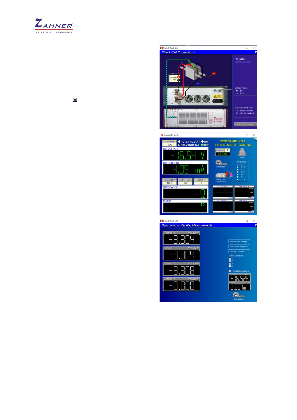
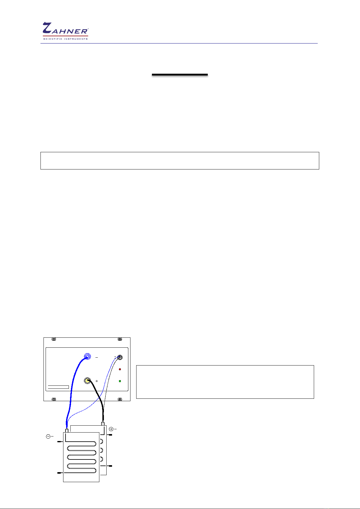
Cell connections ...............................................................................................................11
EL1000 operation steps ....................................................................................................12
1. Full cell configuration ..................................................................................................13
a. Current setting in EL1000 ................................................................................13
2.a. Half-cell configuration - Cathode ................................................................................14
2.b. Half-cell configuration - Anode ...................................................................................14
3. Partial cell configuration ............................................................................................15
a. PAD4 connections ...........................................................................................15
4. Application with an additional DC sink/load ...............................................................16
4.a. DUT connected with DC load and EL1000 .................................................................16
4.b. DUT connected with DC load and EL1000 (in parallel)...............................................17
5. Applications with an additional power supply .............................................................18
5.a. Charging batteries......................................................................................................18
5.b. Electrolysis of fuel cells ..............................................................................................19
5.c. Compensation of voltage drop (Zero Volt Option).......................................................20
6. Applications with an additional power supply (external input) ......................................21
Built-in buffer amplifier......................................................................................................23
Grounding circuit ..............................................................................................................23
Specifications....................................................................................................................24