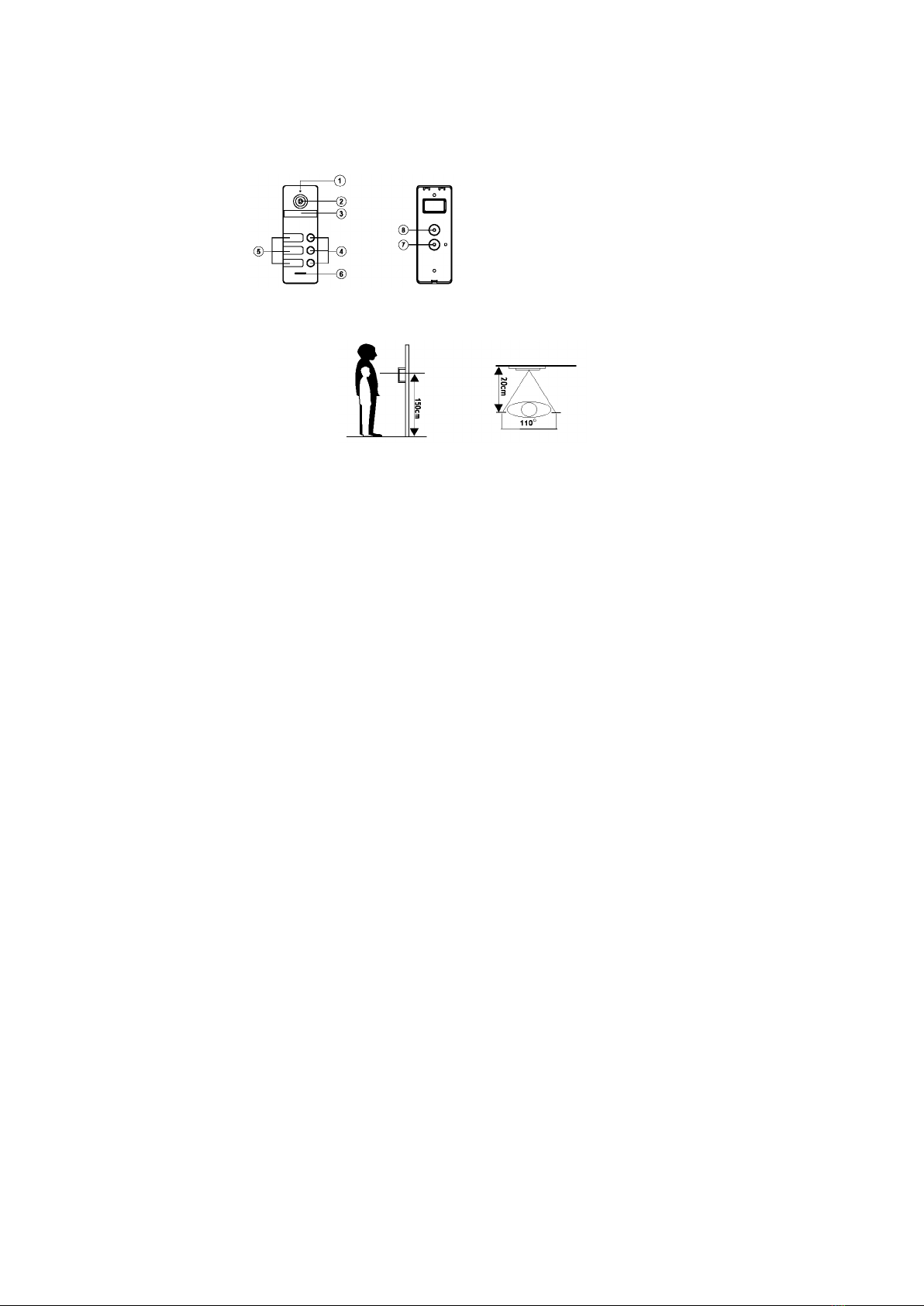
Zamel VO-803B User manual

By system działał poprawnie w ustawieniach zaawansowanych monitora należy zmienić ustawienia typu
instalacji na wielorodzinny. Panel zewnętrzny należy podpiąć do złącza odpowiadającego za Drzwi 1.
Dziękujemy za wybór naszego produktu.
Firma Zamel nie odpowiada za uszkodzenia oraz wypadki spowodowane
niezgodnym z przeznaczeniem użytkowaniem produktu.
Przed przystąpieniem do montażu w celu prawidłowego użytkowania należy
zapoznać się dokładnie z instrukcją obsługi.
Zabrania się otwierania oraz wszelakiej nieautoryzowanej ingerencji w urządzenie.
Nie stosowanie się do powyższego skutkuje utratą gwarancji.
PANEL ROZMÓWNY
VO-803B/VO-803S
SCHEMAT PODŁĄCZENIA
Należy wybrać odpowiedni zależnie od typu elektrozaczepu.
styk zwierny
ELEKTROZACZEP
OKABLOWANIE NO
-
Zasilanie
Czerwony
Niebieski
Żółty
Czerwony
Niebieski
Żółty
Biały
(ACDC5V~24V)
AD
GND
PWR
VD
+
MIESZKANIE 1
ZŁĄCZE P1
DRZWI 1
MONITORA
zasilanie rygla +
WI ZKA 1Ą
WI ZKA 2Ą
•
•
•
•
AUDIO1
GND
_
12V IN1
VIDEO1
•
•
•
NO
COM
NC
Czerwony
Niebieski
Żółty
Biały
AD
GND
PWR
VD
MIESZKANIE 2
ZŁĄCZE P1
DRZWI 1
MONITORA
•
•
•
•
AUDIO2
GND
_
12V IN2
VIDEO2
Czerwony
Niebieski
Żółty
Biały
AD
GND
PWR
VD
MIESZKANIE 3
ZŁĄCZE P1
DRZWI 1
MONITORA
•
•
•
•
AUDIO3
GND
_
12V IN3
VIDEO3
styk zwierny
OKABLOWANIE NC
-
Zasilanie
Czerwony
Niebieski
Żółty
Czerwony
Niebieski
Żółty
Biały
(ACDC5V~24V)
AD
GND
PWR
VD
+
MIESZKANIE 1
ZŁĄCZE P1
DRZWI 1
MONITORA
zasilanie rygla +
WI ZKA 1Ą
WI ZKA 2Ą
•
•
•
•
AUDIO1
GND
_
12V IN1
VIDEO1
•
•
•
NO
COM
NC
Czerwony
Niebieski
Żółty
Biały
AD
GND
PWR
VD
MIESZKANIE 2
ZŁĄCZE P1
DRZWI 1
MONITORA
•
•
•
•
AUDIO2
GND
_
12V IN2
VIDEO2
Czerwony
Niebieski
Żółty
Biały
AD
GND
PWR
VD
MIESZKANIE 3
ZŁĄCZE P1
DRZWI 1
MONITORA
•
•
•
•
AUDIO3
GND
_
12V IN3
VIDEO3
ELEKTROZACZEP

SPECYFIKACJA
OPIS
1. Mikrofon
2. Kamera
3. Podświetlenie LED
4. Przyciski wywołania
5. Okienka Imienne
6. Głośnik
7. Wiązka 2
8. Wiązka 1
7
FRONT TYŁ
1
2
3
4
6
5
Odporność na pył i wodę: IP66
Temperatura pracy :-30℃ to +60℃
Wymiary: 154x55x18mm
Kamera szerokokątna 110°
Wyjście wideo 1Vp-p75Ω
Napięcie zasilania DC 10-15V
Pobór energii: 2.5W
INSTALACJA
1. Należy zastosować się do schematu okablowania a następnie upewnić się co do
poprawności wykonanych połączeń na przewodach.
2. Ustalić pozycję montażu panelu; - zaleca się montaż na wysokości 1,5 -1,6 metra,
3. Wybierając pozycję do zamontowania należy pamiętać o unikaniu ekspozycji kamery
na bezpośrednie działanie słońca oraz na znaczne zacienienia.
4. Upewnić się co do odłączenia napięcia zasilającego (stan beznapięciowy) przed
montażem.
5. Załączyć napięcie zasilające po ukończeniu montażu.
SCHEMAT INSTALACJI
6. W trakcie montażu panela zewnętrznego należy uszczelnić wodoodpornym silikonem
powierzchnie tylnej ściany urządzenia oraz płaszczyznę montażu. Zapobiegnie to
kondensowaniu się pary wodnej na płaszczyźnie styku podczas zmiennych warunków
atmosferycznych. Jej obecność jest niepożądana z uwagi na ryzyko korozji części
elektronicznych oraz niekorzystne warunki podczas ujemnych temperatur.
Montaż bezpośrednio na ścianie lub słupku z wykorzystaniem wspornika 30°
1. Wykonać otwory po uprzednim ustaleniu odpowiedniej wysokości dla instalowanego
panelu.
2. Zamocować wspornik 30° na płaszczyźnie montażu używając kołków oraz wkrętów.
3. Zdjąć wspornik z tylnej ściany panelu.
4. Zamocować wspornik na płaszczyźnie wspornika 30° używając wkrętów.
5. Przeciągnąć przewód poprzez wspornik a następnie połączyć z przewodami od
panelu rozmównego korzystając ze schematu podłączenia.
6. Zamocować panel bramowy na wsporniku mocując śrubę blokującą.
8
GWARANCJA
Panel trzyrodzinny
Montaż natynkowy
Wandaloodporna obudowa ze stopu cynkowego
Rozdzielczość : 800 TVL
Typ sygnału : CVBS
Podświetlanie LED
Wspiera otwarcie NO/NC
1. ZAMEL Sp. z o.o. udziela 24 - miesięcznej gwarancji na sprzedawane towary.
2. Gwarancją ZAMEL Sp. z o.o. nie są objęte:
a) mechaniczne uszkodzenia powstałe w transporcie, załadunku / rozładunku lub innych okolicznościach,
b) uszkodzenia powstałe na skutek wadliwie wykonanego montażu lub eksploatacji wyrobów ZAMEL Sp. z o.o.,
c) uszkodzenia powstałe na skutek jakichkolwiek przeróbek dokonanych przez KUPUJĄCEGO lub osoby trzecie, a odnoszących
się do wyrobów będących przedmiotem sprzedaży lub urządzeń niezbędnych do prawidłowego funkcjonowania wyrobów
będących przedmiotem sprzedaży,
d) uszkodzenia wynikające z działania siły wyższej lub innych zdarzeń losowych, za które ZAMEL Sp. z o.o. nie ponosi
odpowiedzialności.
e) źródła zasilania (baterie), będące na wyposażeniu urządzenia w momencie jego sprzedaży (jeśli występują).
3. Wszelkie roszczenia z tytułu gwarancji KUPUJĄCY zgłosi w punkcie zakupu lub firmie ZAMEL Sp. z o.o. na piśmie po ich
stwierdzeniu.
4. ZAMEL Sp. z o.o. zobowiązuje się do rozpatrywania reklamacji zgodnie z obowiązującymi przepisami prawa polskiego.
5. Wybór formy załatwienia reklamacji, np. wymiana towaru na wolny od wad, naprawa lub zwrot pieniędzy należy do ZAMEL Sp.
z o.o.
6. Terytorialny zasięg obowiązywania gwarancji: Rzeczpospolita Polska.
7. Gwarancja nie wyłącza, nie ogranicza, ani nie zawiesza uprawnień KUPUJĄCEGO wynikających z niezgodności towaru
z umową.

WIRING CONNECTION DIAGRAM
Select according to the electric strike type.
To have the system operate properly, switch the Installation Type to Multi-family in the Advanced Settings of the video
entry phone display. Wire the entrance panel to the connector for 'Door 1'.

Tekst
Translation
OKABLOWANIE NC
NC WIRING
OKABLOWANIE NO
NO WIRING
WIĄZKA
HARNESS
Czerwony
Red
Niebieski
Blue
Żółty
Yellow
Biały
White
MIESZKANIE 1
FLAT NO. 1
ZŁĄCZE P1
P1 CONNECTOR
DRZWI 1 MONITORA
DISPLAY DOOR 1
ELEKTROZACZEP
ELECTRIC STRIKE
styk zwierny
-
normally open contact
-
zasilanie rygla +
latch power supply +
Zasilanie
Power
(ACDC5V~24V)
(ACDC5V~24V)

CALL PANEL
VO-803B / VO-803S
Thank you for buying this product from Zamel.
Zamel shall not accept any liability for any results of damage and/or accidents caused by non-intended use of the
product.
Before attempting installation of this product, read and understand its entire Operating Manual to comply with the
intended use.
Do not open or tamper with the product without prior authorization.
Otherwise your warranty rights for this product will be void.

SPECIFICATIONS
• 3-family panel
• Surface-mounted
• Vandal-resistant zinc alloy housing
• Resolution: 800 TVL
• Signal type: CVBS
• LED illumination
• NO/NC strike control
• Dust and water proof: IP66
• Operating temperature: -30°C to +60°C
• Dimensions: 154x55x18mm
• 110° wide-angle camera
• Video output: 1Vp-p75Ω
• Supply voltage: 10-15V DC
• Input power: 2.5 W
DESCRIPTION
FRONT
BACK
1. Microphone
2. Camera
3. LED illumination
4. Call button
5. Label displays
6. Speaker
7. Harness 2
8. Harness 1
INSTALLATION
1. Follow the wiring connection diagram and verify that all wiring connections are correct.
2. Choose the right place to install the entrance panel in. An installation height between 1.5
and 1.6 m above the ground is recommended.
3. The entrance panel video camera should be away from direct sunlight and deep
shadows.
4. Verify that the power supply voltage is OFF before wiring the device.
5. Power on the supply voltage of the device when completely installed.
6. Seal the back plate edges of the entrance panel all along at the installation surface with
a waterproof silicone product during the installation. This will prevent condensation of
humidity between the entrance panel and its installation surface in certain weather
conditions. Condensation of humidity on the surfaces is a risk of corrosion of electronic
components in the device and mechanical stress from freezing of condensation at low
temperatures.

INSTALLATION DIAGRAM
Directly on a wall or a post with the 30° angle console
1. Select the installation height of the entrance panel and drill the mounting holes on the
installation surface at the desired height.
2. Mount the 30° angle console on the installation surface with wall plugs and their screws.
3. Remove the factory bracket from the entrance panel back plate.
4. Install the removed bracket on the 30° angle console with the screws provided.
5. Pass the connection wiring end through the bracket and connect it to the entrance panel
wiring. Follow the wiring connection diagram.
6. Install the entrance panel on the bracket with the lock screw.
WARRANTY
1. ZAMEL Sp. z o.o. grants a 24-month warranty for the goods it sells.
2. The warranty granted by ZAMEL Sp. z o.o. does not cover:
a) defects caused by transport, handling or other factors;
b) defects caused by improper installation or operation of the products manufactured ZAMEL Sp. z o.o.,
c) defects caused by any modifications or alterations made by the BUYER or any third party to the sold products or to the
equipment required for the proper operation of the sold products;
d) defects caused by any force majeure event or another fortuitous event beyond any reasonable control of ZAMEL Sp. z o.o.;
e) the power supply (batteries) included (if any) with the device as sold.
3. The BUYER shall report all warranty claims in writing at the point of sale or to ZAMEL Sp. z o.o.
4. ZAMEL Sp. z o.o. will examine each warranty claim as regulated by the applicable provisions of the Polish law.
5. If found valid by examination, the warranty claim will be processed by replacement of the defective product, its repair or a
refund of the price of purchase at the sole discretion of ZAMEL Sp. z o.o.
6. This warranty is only effective on the following territories: the Republic of Poland.
7. This warranty does not exclude, limit or suspend any rights of the BUYER arising from the statutory or regulatory laws
concerning implied warranty for defects of sold goods.

ANSCHLUSSCHEMA
Vom Typ abhängige Türöffner auswählen.
Damit das System in den erweiterten Einstellungen des Monitors ordnungsgemäß funktioniert, ist es notwendig, die
Einstellungen des Installationstyps auf Mehrfamilienbetrieb umzustellen. Das Außenelement sollte an den
Anschluss für Tür 1 angeschlossen werden.

Tekst
Übersetzung
OKABLOWANIE NC
NC VERKABELUNG
OKABLOWANIE NO
NO VERKABELUNG
WIĄZKA
BÜNDEL
Czerwony
Rot
Niebieski
Blau
Żółty
Gelb
Biały
Weiß
MIESZKANIE 1
WOHNUNG 1
ZŁĄCZE P1
PORT P1
DRZWI 1 MONITORA
TÜR 1 DES MONITORS
ELEKTROZACZEP
TÜRÖFFNER
styk zwierny
-
Schließkontakt
-
zasilanie rygla +
Stromversorgung für den Riegel +
Zasilanie
Versorgungsspannung
(ACDC5V~24V)
(ACDC5V~24V)

SPRECHANLAGE
VO-803B/VO-803S
Wir bedanken uns für den Kauf unseres Produkts und Ihr entgegengebrachtes Vertrauen.
Die Firma Zamel haftet nicht für Beschädigungen und Unfälle, die aus unsachgemäßem Betrieb oder
unsachgemäßer Nutzung resultieren.
Lesen Sie vor der Montage die Betriebsanleitung aufmerksam durch und befolgen Sie die Anweisungen sorgfältig.
Sämtliche Mängel, die aus Eingriffen resultieren, die nicht von einer geschulten Fachkraft durchgeführt worden sind,
sind nicht durch diese Garantie abgedeckt und führen zu ihrem Erlöschen.

PRODUKTSPEZIFIKATION
• Dreifamilien-Element
• Aufputzmontage
• Vandalismussicheres Gehäuse
• Auflösung: 800 TVL
• Signal: CVBS
• LED-Beleuchtung
• NO/NC Unterstützung
• Staub- und Wasserbeständigkeit
(Schutzart): IP66
• Betriebstemperatur: -30 °C bis +60 °C
• Abmessungen: 154x55x18mm
• Weitwinkelkamera: 110°
• Video-Ausgang: 1Vp-p75Ω
• Versorgungsspannung: DC 10-15V
• Leistungsaufnahme: 2.5W
BESCHREIBUNG
VORDERSEITE
RÜCKSEITE
1. Mikrofon
2. Kamera
3. LED-Beleuchtung
4. Auslösetaste (Klingeltaste)
5. Namensschilder
6. Lautsprecher
7. Bündel 2
8. Bündel 1
INSTALLATION
1. Verbinden Sie die Kabel sorgfältig in Übereinstimmung mit dem Anschlussschema.
2. Wählen Sie die gewünschte Montagehöhe aus: Die empfohlene bzw. optimale
Montagehöhe beträgt ca. 1,5-1,6 m.
3. Stellen Sie sicher, dass der Montageort so gewählt ist, dass die Kamera keiner hohen
Sonnen- bzw. Lichteinstrahlung ausgesetzt ist.
4. Stellen Sie sicher, dass während der Inbetriebnahme bzw. Erstmontage keine
Spannung anliegt.
5. Schalten Sie den Stromkreis ein, nachdem die Montage erfolgt ist.
6. Dichten Sie die Rückseite des Außenelements mit einer Silikondichtung ab und

schützen Sie das Produkt somit vor Wassereintritt und Korrosion. Dadurch wird die
Kondensation von Wasserdampf auf der Kontaktfläche bei wechselnden
Wetterbedingungen verhindert. Wasserdampf ist unerwünscht, da die Gefahr der
Korrosion von elektronischen Bauteilen und ungünstige Bedingungen bei
Frosttemperaturen besteht.
MONTAGE
Wand- oder Pfostenmontage mittels 30° Basis
1. Bohren Sie bei entsprechender Montagehöhe zwei Löcher in die Wand.
2. Montieren Sie die 30° Basis. Verwenden Sie hierzu entsprechende Dübel und
Schrauben.
3. Entfernen Sie die Gehäuserückseite, indem Sie die Blockierschraube lösen.
4. Setzen Sie die Gehäuserückseite auf die 30° Basis und verschrauben Sie diese.
5. Führen Sie die Kabel durch die Basis und verbinden Sie Kabelverbindungen gemäß
Anschlussschema.
6. Setzen Sie das Gehäuse auf und verschrauben Sie die Blockierschraube.
GARANTIE
1. Die Firma ZAMEL Sp. z o.o. gewährt auf ihre Produkte eine Garantie von 24 Monaten.
2. Von der von ZAMEL Sp. z o.o. gewährten Garantie ausgeschlossen sind:
a) Mechanische, die bei Transport, Beladung / Entladung oder in anderen Umständen entstanden sind,
b) Schäden, die infolge mangelhafter Montage oder nicht korrekter Nutzung der Produkte von ZAMEL Sp. z o.o. entstanden
sind,
c) Schäden, die infolge der durch den KÄUFER oder Drittpersonen vorgenommenen Veränderungen der Erzeugnisse, die
Verkaufsgegenstand sind oder der Geräte, die unentbehrlich sind, damit die als Verkaufsgegenstand geltenden Produkte
richtig funktionieren, entstanden sind,
d) Schäden, die durch höhere Gewalt oder andere zufällige Ereignisse entstanden sind, für welche ZAMEL Sp. z o.o. nicht
haftet.
e) die Energiequellen (Batterien), mit denen zum Zeitpunkt des Verkaufs das Gerät ausgestattet war (falls vorhanden).
3. Der KÄUFER ist verpflichtet, sämtliche Garantieansprüche nach deren Feststellung dem Verkäufer oder der Firma ZAMEL
Sp. z o.o. schriftlich zu melden.
4. ZAMEL Sp. z o.o. verpflichtet sich, die Reklamationen nach den geltenden Vorschriften des polnischen Rechts zu prüfen.
5. Die Firma ZAMEL Sp. z o.o. entscheidet über die Form der Reklamationsabwicklung, z. B. Umtausch gegen mängelfreie
Ware, Reparatur oder Erstattung des Kaufpreises.
6. Territorialer Geltungsbereich der Garantie: Republik Polen.
7. Die Bestimmungen der vorliegenden Garantie schließen, schränken und heben keine sich aus der Unstimmigkeit des
Produkts mit dem Vertrag ergebenden Berechtigungen des KÄUFERS aus.
This manual suits for next models
1
Table of contents
Popular Control Panel manuals by other brands

Bigassfans
Bigassfans BAFWorks 3.0 installation guide

Spraying Systems
Spraying Systems AutoJet 2850+ owner's manual

Security Command
Security Command XR20 Executive Series user guide

Fire-Lite
Fire-Lite ACC-25 instruction manual

HIK VISION
HIK VISION DS-PWA32-HR manual

re:3D
re:3D GIGABOT VIKI 2.0 installation manual