_________________________________________________________________________INDEX
____________________________________________________________________________
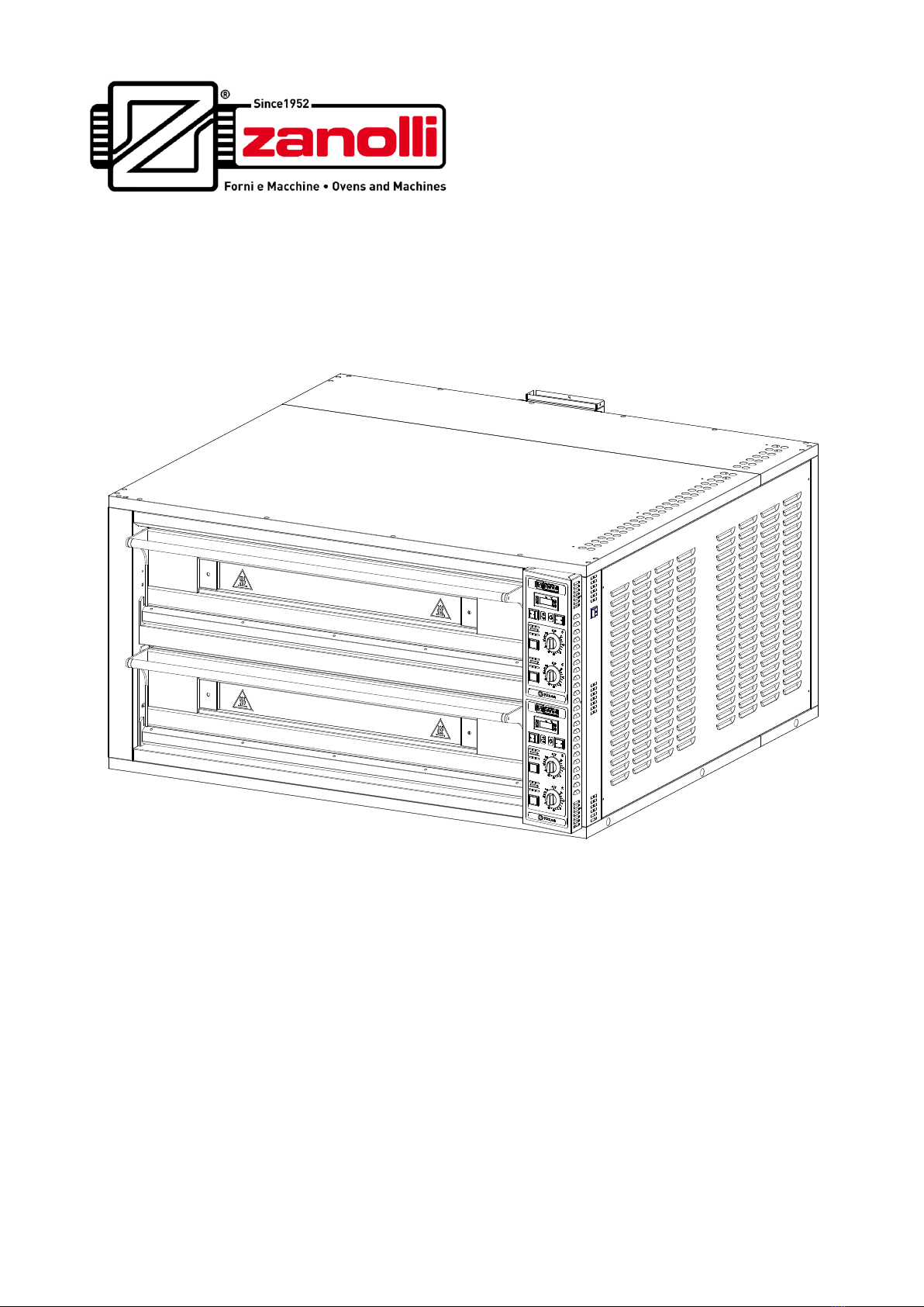
4 CITIZEN 6 - 9/MC, CITIZEN 6+6 - 9+9/MC ELECTROMECHANICAL VERSION
5.2.7 and buttons............................................................................19
5.2.8 OUT display (vers. TERM0012).......................................................19
5.2.9 “out1“ display led green (vers. TERM0060) .............................................19
5.2.10 Power regulators .............................................................19
5.2.11 Oven roof and bedplate
pilot lamps....................................20
5.3 Error display.................................................................................. 20
5.3.1 Short-circuited thermocouple (vers. TERM0012) ....................................20
5.3.2 Disconnected thermocouple (vers. TERM0012) ......................................20
5.3.3 Disconnected thermocouple (vers. TERM0060) ......................................20
6. THE USE OF THE OVEN ........................................................21
6.1 Preparation for use........................................................................ 21
6.2 Ignition of the control panel ......................................................... 21
6.3 Settings.......................................................................................... 21
6.4 Baking start.................................................................................... 21
6.5 Loading the oven........................................................................... 21
6.6 General indications for good cooking ......................................... 22
6.7 Turning off ..................................................................................... 22
7. CLEANING...............................................................................23
7.1 Cleaning the exposed parts.......................................................... 23
7.2 Cleaning the parts made from ceramic refractory material........ 23
7.3 Cleaning the oven's cooking chamber ........................................ 24
7.4 Cleaning external surfaces........................................................... 24
8. MAINTENANCE.......................................................................25
8.1 Ordinary maintenance work ......................................................... 25
8.1.1 Light replacement ......................................................................................25
8.2 Error displays ................................................................................ 25
8.3 Electrical diagram ......................................................................... 26
8.4 Adjustment for different feed voltages ........................................ 26
8.5 Exploded views and spare parts list............................................ 34
9. DECOMMISSIONING AND DEMOLITION..............................39
10. DECLARATION OF CONFORMITY.......................................40