Zareba G452 User manual

SMART SYSTEMS FOR ACCESS CONTROL
AUTOMATIC GATE OPENER
INSTALLATION MANUAL
Model G452
For Double Gates
Part #7001623.002 Rev. 1

AUTOMATIC GATE OPENER • G452 Installation Manual
2
GATE OPENER CLASS CATEGORIES*
The Zareba Automatic Gate Opener is intended for use with vehicular swing gates. The opener can be used in Class I,
Class II, Class III and Class IV applications.
Residential Vehicular Gate Opener–Class I: A vehicular gate opener (or system) intended for use in a home of one-to-four
single family dwelling, or a garage or parking area associated therewith.
Commercial/General Access Vehicular Gate Opener–Class II: A vehicular gate opener (or system) intended for use in a
commercial location or building such as a multifamily housing unit (five or more single family units), hotel, garages,
retail store or other building servicing the general public.
Industrial/Limited Access Vehicular Gate Opener–Class III: A vehicular gate opener (or system) intended for use in an
industrial location or building such as a factory or loading dock area or other locations not intended to service the gen-
eral public.
Restricted Access Vehicular Gate Opener–Class IV: A vehicular gate opener (or system) intended for use in a guarded
industrial location or building such as an airport security area or other restricted access locations not servicing the gen-
eral public, in which unauthorized access is prevented via supervision by security personnel.
*Categories established by Underwriters Laboratories for vehicle gate operators (openers).
FOR YOUR RECORDS
Please record the serial number (found on the control box cover) and purchase information below. Keep this with your
proof of purchase (receipts) in case your product is lost, stolen or requires service.
Serial number: ________________________________________________________________________________
Purchase date: ________________________________________________________________________________
Retailer/store name: ____________________________________________________________________________
Location of purchase: City __________________________________________ State________________________

3
READ THIS FIRST
WARNING OF RISKS, PURCHASER’S RESPONSIBILITIES, AND
ASSUMPTION OF CERTAIN RISKS:
The directions for installation and use of the Product must be followed carefully. It is impossible to eliminate all
risks inherently associated with the use of the Product. The effectiveness of the Zareba Automatic Gate Opener
depends on proper installation and the manner of use or application, all of which are beyond the control of Zareba
Systems or the seller. All such risks are assumed by the purchaser by the purchaser’s installation and use of the
Product.
The Zareba Automatic Gate Opener is for use on vehicular fence gates only. The Product meets or exceeds the
requirements of UL 325, the standard that regulates gate opener safety, as established and made effective March
14, 2003, by Underwriters Laboratories, Inc.
Zareba Systems
906 Fifth Avenue E
Ellendale, MN 56026-2193
Toll free: 800-272-9877
Phone: 507-684-3721 Fax: 507-684-3722
Email: info@zarebasystems.com
zarebasystems.com
Warning: Before installing your Zareba Automatic Gate Opener (sometimes also referred to as the
“Product”), read this entire Installation Manual for information about Product safety matters and
proper use of the Product. Only use the Product for the purpose of a vehicular fence gate.

AUTOMATIC GATE OPENER • G452 Installation Manual
4
Table of Contents
An Introduction to Automatic Gate Openers . . . . . . . . . . . . . . . . . . . . . . . . . . . page 5
Important Safety Information
General Safety Information . . . . . . . . . . . . . . . . . . . . . . . . . . . . . . . . . . . . . . . . . . . . . . page 5
Protection Against Entrapment . . . . . . . . . . . . . . . . . . . . . . . . . . . . . . . . . . . . . . . . . . . page 6
Warning Signs and Labels . . . . . . . . . . . . . . . . . . . . . . . . . . . . . . . . . . . . . . . . . . . . . . . page 7
Additional Safety Devices . . . . . . . . . . . . . . . . . . . . . . . . . . . . . . . . . . . . . . . . . . . . . . . . page 8
Pre-Installation Information
Tools and Parts List . . . . . . . . . . . . . . . . . . . . . . . . . . . . . . . . . . . . . . . . . . . . . . . . . . . . . page 9
Technical Specifications . . . . . . . . . . . . . . . . . . . . . . . . . . . . . . . . . . . . . . . . . . . . . . . . page 12
Important Gate Information . . . . . . . . . . . . . . . . . . . . . . . . . . . . . . . . . . . . . . . . . . . . . page 12
Installation
Overview . . . . . . . . . . . . . . . . . . . . . . . . . . . . . . . . . . . . . . . . . . . . . . . . . . . . . . . . . . . . page 13
Bracket Mounting . . . . . . . . . . . . . . . . . . . . . . . . . . . . . . . . . . . . . . . . . . . . . . . . . . . . . page 13
Installation of Gate Openers (Actuators) . . . . . . . . . . . . . . . . . . . . . . . . . . . . . . . . . . . page 18
Installation of the Control Box . . . . . . . . . . . . . . . . . . . . . . . . . . . . . . . . . . . . . . . . . . . page 18
Power Connection Between Control Box and Gate Openers (Actuators) . . . . . . . . . . page 18
Push-to-Open Installation . . . . . . . . . . . . . . . . . . . . . . . . . . . . . . . . . . . . . . . . . . . . . . page 22
Brick, Masonry or Rock Column Installation . . . . . . . . . . . . . . . . . . . . . . . . . . . . . . . . page 24
Control Box Setting
Control Board Settings . . . . . . . . . . . . . . . . . . . . . . . . . . . . . . . . . . . . . . . . . . . . . . . . . page 24
Dual DIP Switch Settings and Descriptions . . . . . . . . . . . . . . . . . . . . . . . . . . . . . . . . . page 25
Transmitter Set Up . . . . . . . . . . . . . . . . . . . . . . . . . . . . . . . . . . . . . . . . . . . . . . . . . . . . page 26
Setting the Gate’s Closed Limit Position . . . . . . . . . . . . . . . . . . . . . . . . . . . . . . . . . . . page 27
Automatic Close Time Adjustment . . . . . . . . . . . . . . . . . . . . . . . . . . . . . . . . . . . . . . . page 28
Obstruction Sensitivity Set Up . . . . . . . . . . . . . . . . . . . . . . . . . . . . . . . . . . . . . . . . . . . page 29
Accessory Installation . . . . . . . . . . . . . . . . . . . . . . . . . . . . . . . . . . . . . . . . . . . . . . . . . . page 29
Operation
Charging the Battery . . . . . . . . . . . . . . . . . . . . . . . . . . . . . . . . . . . . . . . . . . . . . . . . . . page 29
Gate Opener Operation . . . . . . . . . . . . . . . . . . . . . . . . . . . . . . . . . . . . . . . . . . . . . . . . page 29
Manual Operation of Gate . . . . . . . . . . . . . . . . . . . . . . . . . . . . . . . . . . . . . . . . . . . . . . page 30
Theft Deterrence . . . . . . . . . . . . . . . . . . . . . . . . . . . . . . . . . . . . . . . . . . . . . . . . . . . . . . page 30
Maintenance and Troubleshooting Guide . . . . . . . . . . . . . . . . . . . . . . . . . . . . . page 31
Warranty and Repair Information . . . . . . . . . . . . . . . . . . . . . . . . . . . . . . . . . . . page 33
Gate Opener Accessories . . . . . . . . . . . . . . . . . . . . . . . . . . . . . . . . . . . . . . . . . . . . page 34
Gate Opener and Accessory Order Form . . . . . . . . . . . . . . . . . . . . . . . . . . . . . . page 35

You may obtain additional copies of this manual from
our web site at www.zarebasystems.com, or contact
Zareba Systems at: 906 5th Ave. E, Ellendale, MN
56026, 1-800-272-9877.
IMPORTANT SAFETY
INFORMATION
General Safety Information
Vehicular gates are large heavy objects. Automatic gate
openers provide a convenient way to open and close
the gates. Since the gate system and its components
exert a high level of force to open and close the gate,
they can be dangerous, causing severe injuries and
death to you and others.
Your safety and the safety of others depend on the
owner and users of this system to read, understand,
and follow the information and instructions in this man-
ual. Save this safety information for future use.
Safety overview checklist
WARNING – To reduce the risk of injury or death:
• Use this operator with single or double swing gates.
• READ AND FOLLOW ALL INSTRUCTIONS.
• Never let children operate or play with gate controls.
Keep the remote control away from children.
• Always keep people and objects away from the gate.
NO ONE SHOULD CROSS THE PATH OF THE MOVING
GATE.
• Test the gate operator monthly. The gate MUST
reverse on contact with a rigid object or stop when an
object activates the non-contact sensors. After adjust-
ing the force or the limit of travel, retest the gate oper-
ator. Failure to adjust and retest the gate operator
properly can increase the risk of injury or death.
• KEEP GATES PROPERLY MAINTAINED. Read the owner’s
manual. Have a qualified service person make repairs
to gate hardware if needed.
• The entrance is for vehicles only. Pedestrians must use
a separate entrance.
• SAVE THESE INSTRUCTIONS
• Remember that the Zareba Automatic Gate Opener
must only be installed on gate systems meeting the
requirements of the application.
• Ensure that you are using the correct opener for the
type and size of gate, its frequency of use and the
class rating.
5
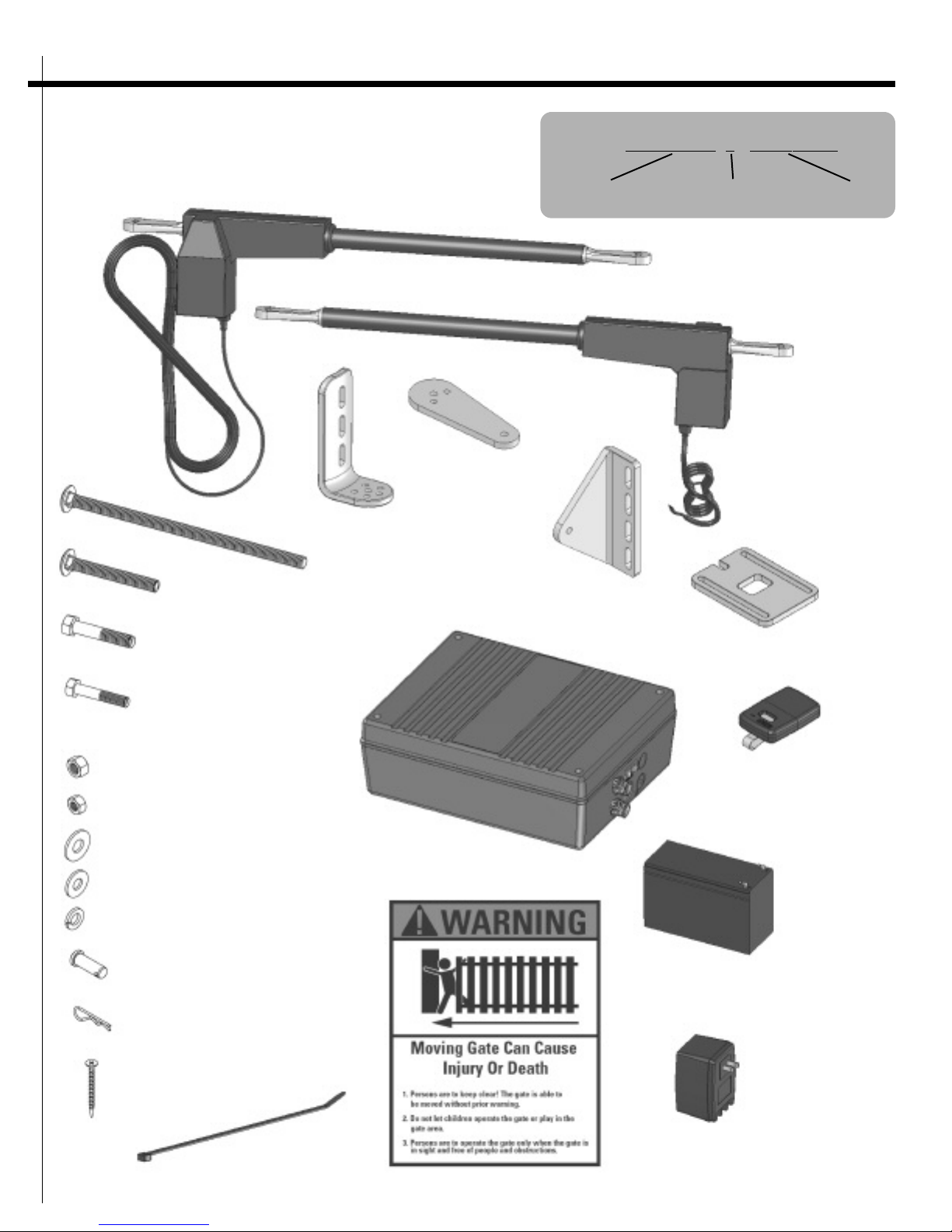
Thank you for purchasing the Zareba Automatic Gate
Opener.
Your Zareba Automatic Gate Opener is designed for
years of trouble free performance. It will provide you
with a comfortable, safe, hassle-free way to access your
property.
This Automatic Gate Opener is designed to work on sin-
gle or dual swing gates. Each individual gate can be up
to 14 feet long and weigh up to 450 pounds. Your gate
opener will work on a variety of gate types such as iron,
tubular, chain link, vinyl, etc. It is not recommended to
use an automatic gate opener on a solid fence due to
wind resistance. Depending on the strength of the wind
and the obstruction sensing, your gate may not operate
properly.
Your Zareba Automatic Gate Opener can be opened
and closed in a variety of ways. Primarily, you will use
your remote transmitter (included with your unit) to
open or close the gate. However, the gate can also be
opened with a hardwired button, an automatic vehicle
sensor, a keypad, or built-in vehicle transmitter systems.
These accessories are discussed later in this manual. The
gate can also be closed with the hardwired button or
keypad. In addition it can be closed automatically using
a time delay that is set in the control box.
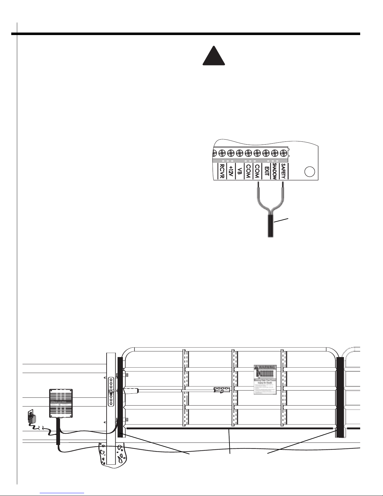
Your Zareba Automatic Gate Opener is designed to pro-
vide for safe operation. One of the most important fea-
tures of your gate opener is obstruction sensing. Your
gate opener includes an adjustment for setting the sen-
sitivity of the obstruction performance. When there is
an obstruction that prevents the gate from opening or
closing, the gate will immediately stop and reverse
direction. If the obstruction is removed the gate may be
activated to continue its path from where it stopped. If
the obstruction is not removed, the gate opener will
sound an alarm and will not operate again until the
gate opener system is reset.
There are a number of accessories that can be installed
with your gate opener that maximize your benefit to
owning the system. The accessories include additional
transmitters, keypad, pin lock, solar panel, in-ground
vehicle sensor, and others. Please see Gate Opener
Accessories at end of this manual.
AN INTRODUCTION TO
AUTOMATIC GATE
OPENERS

AUTOMATIC GATE OPENER • G452 Installation Manual
• Ensure that the gate and gate opener installation com-
ply with applicable local codes.
•Contact local fire and law enforcement to arrange
emergency access procedures.
• Keep people, animals, and property away from the
gate area. Do not let children play in or near the gate
area.
• Use caution with moving parts to avoid injuring fin-
gers or hands.
• Consider installing contact sensors, or non-contact
sensors to provide additional safety and protection
against entrapment.
• Never activate your gate opener until you ensure that
the area is clear of people, pets, or other obstructions.
Watch the gate until it stops.
• Do not drive forward until the gate stops completely.
Protection Against Entrapment
Important! Study Figures 1 and 2, and keep safety fore-
most at all times.
Entrapment areas for a proper
pull-to-open installation
Entrapment Area 1
Hinged edge of the gate and the fence post.
Entrapment Area 2
Between the ends of the two gates.
Entrapment Area 3
The path of the gate.
Entrapment Area 4
The space between the gate in the open position and
any object such as a wall, fence, tree, etc.
Entrapment Area 5
Pinch points between the opener and gate or post.
Area 1
Area 2
Area 3
Area 5
driveway
Figure 1
gates in open position
fence
Area 4
Moving Area of Gate
Never install any control device
(such as a Push Button) within
10’ of any moving gate part
10’
10’
Figure 2
fence fence
6
Moving Area of Gate
driveway
fence
Area 5
Area 4
Area 1
Area 3
10’
10’ 10’

Entrapment Alarm
(UL 325; 30.1)
In compliance with UL 325 the Zareba Automatic Gate
Opener is designed to stop and reverse direction within
two seconds of sensing an obstruction. In addition, the
Zareba opener activates an audible alarm if the unit
incurs an obstruction twice while opening or closing.
This alarm sounds for five minutes, or until the opener
receives a renewed, intended input from a hardwired
control such as the Push Button Control. At that point
the gate returns to a fully open or fully closed position.
Turning the power switch on the control box OFF and
back ON also deactivates the alarm.
Warning Signs and Labels
Required Safety Precautions for Gates
WARNING SIGNS alert people of automatic gate opera-
tion. They are required when installing the Zareba
Automatic Gate Opener. If pedestrians will be in the
area, install a walk-through gate for their use.
Warning Signs
The warning signs (fig. 3) must be installed on both
sides of the gate.
These warning signs and labels (fig. 4-5) must appear
at the locations specified below. If any were missing
when the gate opener was purchased, immediately
contact Zareba Systems for replacements.
7
Protection Against Entrapment
The Zareba Automatic Gate Opener is designed to com-
ply with UL 325, the safety standard covering automatic
gate opening systems. UL 325 requires that gate open-
ing systems shall have an inherent entrapment sensing
system and shall have the provisions for, or be supplied
with, at least one independent secondary means to pro-
tect against entrapment.. The primary means of entrap-
ment protection in the Zareba Automatic Gate Opener
is Type A, an inherent means of entrapment protection.
The secondary means of entrapment protection in the
Zareba Automatic Gate Opener is Type B2, the provision
for the connection of a contact sensor (edge sensor).
The gate opener’s built-in means of entrapment protec-
tion (Type A) may not be sensitive enough to prevent
bodily injury in some circumstances. Secondary means
of entrapment protection (Type B2), such as contact
(safety edge) sensors are suggested for enhanced safety.
See page 8 for important information on additional
safety devices.
Figure 3
Warning signs (two enclosed) to be
installed on each side of the gate (three to
five feet above the bottom of the gate)
Figure 4
Product identification and manual operation instruction label
installed on control box cover
Figure 5
Warning labels,
one on each side of
gate opener arm

AUTOMATIC GATE OPENER • G452 Installation Manual
8
Additional Safety Devices
The Zareba Automatic Gate Opener features built-in
obstruction sensitivity. The opener is designed to stop
and reverse the gate within two seconds of contact with
an obstruction. However, the gate opener’s built-in
obstruction settings, even when properly adjusted, may
not be sensitive enough to prevent injury in some cir-
cumstances. See page 29 for more information.
Safety devices, such as contact (safety edge) sensors or
non-contact (photoelectric) sensors, that stop and
reverse gate direction upon sensing an obstruction are
suggested for additional protection.
Zareba Systems recommends using additional safety
devices. Be sure to use products that are certified and
that comply with applicable UL standards and national
and regional safety codes. Call Zareba Systems at 1-800-
272-9877 for information on compatible products for
your application.
Important: In all cases, review the safety-device manu-
facturer’s instructions for information on installing
these devices on a vehicular gate.
Contact Sensors (safety edges)
Contact sensors are also referred to as “safety edges.”
Activating a properly installed contact sensor while the
gate is moving causes the gate to stop and reverse with-
in two seconds.
Contact sensors must be mounted in compliance with
UL 325, the Underwriters Laboratories safety standard
for gate openers (see fig. 6).
Turn off the power switch to the openers
(actuators) before connecting safety device
wiring to the terminal blocks. Unplugging
the transformer does not turn off power to
the openers.
Contact Sensor Input Connection (fig. 7)
Connect one of the SAFETY contact sensor wires to the
COMMON (COM) terminal and the other to the SAFETY
terminal on the gate opener control board.
wire from contact sensor
Figure 7
Figure 6
Contact Sensor (not included)
!

9
Non-Contact Sensors (photoelectric beams)
Non-contact sensors, also called photoelectric beams,
enhance safety by monitoring the path of the safety
beam when the gate is closing. Obstructing the safety
beam path activates the non-contact sensor, which
reverses the gate to the fully open position.
Non-Contact Sensor Connection (fig. 8)
Connect one of the non-contact sensor dry contact out-
put wires to the COMMON (COM) terminal and the
other to the SAFETY terminal on the gate opener con-
trol board.
Tools and Parts List
Tools needed
• Power drill
• Open-end wrenches — 3/8”, 7/16”, 1/2”, and 9/16”
• 3/8” Drill bit
• Hacksaw or heavy-duty bolt cutters
• Small (flat-bladed) screwdriver
• Phillips screwdriver
• Tape measure
• Level
• Wire strippers (for stripping the transformer cable)
• C-clamps
Parts (see fig. 9)
Mounting hardware
Clevis pin clip (4); 3/8” x 1-1/4” Clevis pin (4); 5/16” x
1-3/4” Bolt (2); 3/8” x 2” Bolt (2); 3/8” x 3” Bolt (8);
3/8” x 8” Bolt (12); 8” Nylon cable tie (28); 3/8”
Washer (22); 3/8” Lock washer (22); 5/16” Washer (2);
3/8” Nut (22); 5/16” Nut (2); 2” Mounting screw (10).
Gate Opener
Gate opener (actuator) (1) with 10’ power cable; Gate
opener (actuator) (1) with 40’ power cable; Gate brack-
et (2); Post pivot bracket (2); Post bracket (4); Closed-
position stop plate (2).
Control Box and Electrical Components
Transformer (1); Battery (1); Control box (1); Warning
signs (4); Transmitter(1).
Other Items You May Need for Installation
• Low-voltage wire. This is needed to run from the
transformer to the control box. You’ll need enough to
cover the distance between the transformer power
supply and the control box. See Installation of the
Transformer on page 21 and the List of Accessories on
page 34.
• 5-watt Solar Panel(s). If your gate is more than 1000’
away from an AC power source, you will need at least
one 5-watt Solar Panel to trickle charge the battery.
See the List of Accessories on page 34.
• Threaded rods or carriage bolts longer than 8”.
You will need these if your fence post is more than 6”
in diameter.
• Reinforcement supplies. If you have thin-walled tube
or panel gates, use wood or metal reinforcement
plates or pipes.
• A horizontal cross member or mounting plate. A
horizontal cross member or mounting plate may be
necessary on some types of gates. This would mount
the front of the opener and gate bracket to the gate.
PRE-INSTALLATION
INFORMATION
wire from non-contact sensor
(photo beam)
Figure 8
Important Information About the
Gate Opener Battery:
Upon initial installation, the battery may not be
charged adequately. To ensure proper operation
allow the battery to fully charge prior to initial use. It
should take about four hours to charge a completely
drained battery. The battery can be charged by either:
1. Using a 2 amp battery charger.
2. Following the normal gate opener installation pro-
ceedures through the Charging the Battery section
on page 29, and allowing it to fully charge using
AC power.

AUTOMATIC GATE OPENER • G452 Installation Manual
10
Clevis pin clip (4)
(7001224.001)
2” Mounting screw(10)
(7001225.001)
3/8” x 1-1/4” Clevis pin (4)
(7001223.001)
3/8” Washer (22) (7001226.001)
5/16” Nut (2) (7001230.001)
3/8” Nut (22) (7001229.001)
3/8” x 8” Bolt (12) (7001237.001)
8” Nylon cable tie (28)
(7001231.001)
3/8” x 3” Bolt (8) (7001220.001)
5/16” x 1-3/4” Bolt (2) (7001222.001)
3/8” x 2” Bolt (2) (7001221.001)
3/8” Lock washer (22) (7001227.001)
Gateopener (actuator) with 10’ power cable (1) (7001618.001)
Gate bracket (2)
(7001215.001)
Postbracket (4)
(7001217.001)
Postpivot bracket (2)
(7001218.001)
Closed-position stop plate(2)
(7001216.001)
Control box(1)
(7001620.002)
Warning signs (4)
(7001181.001)
Transformer (1)
(7001212.001)
Battery(1)
(7001155.001)
Transmitter (1)
(7001213.001)
Figure 9 HOW TO READ PART LABELS:
Post bracket (2) (7001217.001)
part description included
part quantity order item
number
Gate opener (actuator) with 40’ power cable (1) (7001618.003)
5/16” Washer (2) (7001226.001)

11
Installed Automatic Gate Opener
Transformer
Gateopener (actuator)
Control box
Closed-position stop plate
Gate bracket
Post bracket
Gate opener (actuator)
Buried power cable

AUTOMATIC GATE OPENER • G452 Installation Manual
12
Technical Specifications
System Power
• The system is powered by a 12 VDC, 7.2 Ah, sealed,
rechargeable lead-acid battery.
• The battery is charged by a 120 to 18 VAC step-down
transformer which supplies power to an integrated 1
amp charger on the Zareba gate opener control
board.
• The control board is protected by one 15 amp blade-
style fuse.
• Optional Zareba Solar Panel for charging battery. The
solar panel provides voltage, current, and power of
16.5 VDC, .300 amps, and 5 watts of power,
respectively.
Voltage Ratings
18 VAC Transformer: 18.0 to 22.0 VAC
5 W Solar panel (single): 16.5 to 22.0 VDC 300 mA
12 V Battery: 12.0 to 13.5 VDC 7.2 Ah
Charging circuit: 12.0 to 14.8 VDC
Gate Drive
• Linear actuator temperature range: -30°F to 120°F
(-34°C to 49°C).
• Powered by a 12 VDC motor.
• Load capacity up to 2000N.
• Maximum opening arc of 130°. Approximate opening
time (90°): 20 seconds, depending on weight of gate.
Gate Control Panel
• Gate opener’s microprocessor-based control board is
factory set for single or dual, pull-to-open gate
installations.
• DIP switches can be adjusted for dual or push-to-open
gates to facilitate gate opener set-up.
• RF receiver tuned to 310 MHz.
• Opener length with push-pull tube fully retracted is
32.5 inches.
• Adjustable auto-close timer (OFF to 120 seconds) and
obstruction sensitivity.
• Provisions made for digital keypads, pull-to-
open/push-to-open buttons, contact (safety edge)
sensors, and non-contact (photoelectric) sensors.
• Audible entrapment alarm.
Operational Capacity
• The Gate Capacity Chart shows the approximate
cycles per day you can expect when the battery is
being charged with transformer and AC power.
Important Gate Information!
Inspect the gate to ensure that it is in proper condition
for the installation of the gate opener. Take steps as nec-
essary to meet these requirements.
The following criteria MUST be met prior to installation:
• The gate is plumb, level, and swings freely on its
hinges.
• No wheels are attached to the gate.
• The gate moves throughout its arc without binding or
dragging on the ground.
• Gates weighing more than 250 lbs. use ball-bearing
hinges with grease fittings.
• The fence post is secured in the ground with concrete
to minimize twist or flex when the opener is activated.
• If your gate lacks a horizontal or vertical cross mem-
ber, add one to provide a stable area for mounting
the gate bracket.
One Cycle =
one open + one close
Gate Capacity Chart
Estimated number of daily cycles, based on use
with a transformer and one 12-Volt battery
Gate
Length
14 ft165 157150 142 135 127
12 ft 170 162 155 147 140 132
10 ft175167160 152 145 137
4-8 ft180 172 165 157 150 142
50 lb 100 lb 200 lb 300 lb 400 lb 450 lb
Gate Weight

13
Overview
This section begins with installation instructions for
gates that open into the property or “pull-to-open”
gates.
To mount the opener on a brick, masonry, or rock col-
umn, refer to page 24.
If you have a push-to-open gate, you must use a push-
to-open bracket (sold separately). See Push-to-Open
Installation on page 22.
For any installation, having another person assist the
installer is helpful.
Bracket Mounting
The proper position of the mounting brackets is crucial
to the efficiency and leverage of the gate opener. The
distance between the gate opener (actuator) and the
gate is also determined by the proper position of the
mounting brackets.
NOTE: Ensure a minimum 2” space exists between the
gate and the gate opener (actuator) for safety reasons.
The curved design of the post
brackets accommodates either
round or square posts. When
mounting the post brackets (see
fig. 10), use bolts long enough
to pass through the entire post.
When mounting the post brack-
ets to wooden posts, use a larg-
er-size washer or metal plate
between the bolts and the wood
post to ensure the stability of the
fastening hardware when thrust
is applied.
If you are using gate posts small-
er than 6” diameter or square,
they should be (1) made of
metal, and (2) set in cement to
ensure the stability of the post.
Gate Reinforcement Methods (fig. 11)
IMPORTANT: Use wood or metal reinforcement plates
or pipes (not included) when mounting the gate brack-
et to thin-walled tube gates or panel gates.
Identify the Correct Mounting Positions of
the Gate Bracket and the Post Mount
Bracket Assembly
This section presents instructions for identifying the cor-
rect mounting position of the gate bracket and the post
mount bracket assemblies for pull-to-open gates. For
push-to-open gates, see Push-to-Open Installation on
page 22.
NOTE: The direction a gate opens and closes is deter-
mined by standing inside the gated property and facing
towards the gate.
Step 1 (fig. 12)
Assemble both the post mount bracket assemblies by
placing the post pivot bracket between the two post
mount brackets. Insert the 3/8” x 2” hex bolt through
the center hole of the two post mount brackets and the
post pivot bracket. Place a 3/8” washer, a 3/8” lock
washer, and a 3/8” hex nut on the bottom of the 3/8” x
2” hex bolt and hand tighten.
INSTALLATION
Metal plate or
large washer
Wooden post
Post pivot bracket
Post mount bracket
Metal plate or
large washer
Wooden post
Post mount bracket
Post pivot bracket
Figure 10

AUTOMATIC GATE OPENER • G452 Installation Manual
14
Step 2 (fig. 13a & 13b)
NOTE: Gate openers (actuators) MUST be in the fully
retracted position before attaching the gate bracket
and the post mount bracket assembly.
Attach the gate bracket and the post mount bracket
assembly to the gate openers (actuators) by inserting a
clevis pins through the holes in the gate brackets and
the post pivot brackets and the clevis at each end of the
gate openers (actuators). Secure the clevis pins using
the clevis pin clips.
Figure 11
Method Two
Method One
Thin-walled
tube gate
Gate bracket
Wood or metal
reinforcement
(not included)
Steel pipe cut in half (inside
diameter of pipe should equal
outside diameter of gate)
Thin-walled
tube gate
Clevis pin clip
Post bracket
assembly
3/8” x 1 1/4”
clevis pin
Gate opener (actuator)
Clevis pin clip
Gate bracket
3/8” x 1 1/4”
clevis pin
Gate opener (actuator)
Figure 13a
Figure 13b
Figure 12
3/8” lock washer
Post brackets
3/8” x 2” bolt
3/8” nut
3/8” washer
Pivot Bracket
Note: secure 5/16” x
1 3/4” bolt in one of
these holes

15
Step 3 (fig. 14)
With the gates in their desired open posi-
tions (from 0° to 130° from the gate’s
closed position) and with the gate open-
ers (actuators) in their retracted posi-
tions, place the gate opener (actuator)
with the gate bracket and post mount
bracket assembly on to the gate post and
the gate. Position the gate bracket and
the post mount bracket assembly so that
the gate opener (actuator) is level with
the horizontal cross member of the gate.
Tip: Locate the gate opener (actuator) in
approximately the middle between the
top and bottom of the gate. This will pre-
vent the gate from twisting and flexing.
While holding the gate opener (actuator)
in the desired level position, temporarily
secure with two C-clamps. Use one C-
clamp to temporarily secure the gate
bracket to the gate. Use the other C-
clamp to temporarily fasten the post
mount bracket assembly to the gate
post.
Step 4 (fig. 15)
Determine the optimum position of the pivot bracket
on the post mount bracket assembly by ensuring a mini-
mum 2” clearance exists between the gate and the gate
opener (actuator) in both the gate-open and gate-closed
positions. To ensure the 2” clearance mini-
mum is maintained in the gate-closed
position, remove the clevis pin from the
gate bracket while holding the gate open-
er; then close the gate. Move the gate
opener (actuator) so the gate bracket and
the gate opener are aligned.
NOTE: Ensure the gate opener (actuator)
and the pivot bracket do not bind in the
gate-open and gate-closed positions.
If the proper clearance cannot be
achieved, turn over the pivot bracket and
try a different alignment position. You
may also move the post pivot bracket
assembly slightly to the right or left to
obtain the proper clearances.
After you’ve identified the desired posi-
tion of the pivot bracket, place the 5/16” x
1” hex bolt into the desired pivot hole on
the post mount bracket.
Gate opener (actuator)
Gate bracket
Fence post
Post bracket
assembly
Figure 14
Note: gate in
open position
Gate in OPEN position
Gate in CLOSED position
Pinch areas
2” min.
2”
min.
Ensure gate opener
arm and pivot
bracket do not bind
Figure 15
Post mount bracket
Pivot holes
3/8” x 2” bolt
5/16” x 1”
hex bolt
5/16” washer
5/16” nut

AUTOMATIC GATE OPENER • G452 Installation Manual
16
Secure the Gate Bracket and the Post
Mount Bracket Assembly to the Gate and
the Gate Post
Step 5
Mark the bolt-hole locations on the gate and the gate
post. Do this by placing a punch or a mark in the mid-
dle of each bolt slot on the gate bracket and the post
mount bracket assemblies. (Marking the bolt-hole loca-
tions in the middle of each bolt slot permits slight
adjustments to the mounting brackets.)
Once you have marked the bolt-hole locations on the
gate and the gate post, remove the gate bracket and
the post mount bracket assembly by taking off the C-
clamps.
Step 6 (fig. 16)
Using a drill and a 3/8” bit, drill holes through the gate
post and the gate at the marked bolt-hole locations.
NOTE: When drilling holes into the gate post and the
gate, keep the drill level and ensure the holes come out
at 180° on the other side.
Step 7 (fig. 17)
Attach the post mount bracket assemblies to the gate
posts by inserting six 3/8” x 8” carriage bolts though
each post mount bracket assembly and the drilled holes
in the gate post. Fasten each carriage bolt with one
3/8” washer, one 3/8” lock washer, and one 3/8” hex
nut.
Post bracket
assembly
Mark fence post and
drill 3/8” holes
3/8” x 8”
bolts
Figure 16
3/8” washer
3/8” x 8”
carriage bolts
Figure 17
3/8” lock washer
3/8” hex nut
INCORRECT!
Post bracket
NOT straight
CORRECT!
Post bracket
is straight

Step 8 (fig. 18)
Attach the gate brackets to each gate by
inserting four 3/8” x 3” carriage bolts
through the gate brackets and the drilled
holes in the gates. Fasten each carriage bolt
with one 3/8” washer, one 3/8” lock wash-
er, and one 3/8” hex nut.
Installing the Gate Stop Plate
NOTE: Mounting hardware for the gate
stop plate is not included. For wood gates,
use wood or lag screws. For tube or chain
gates, use U bolts.
Step 9 (fig. 19)
With the gate in the desired closed position,
loosely fasten the gate stop plate to the
middle of the gate between the top and
bottom at the end of one gate. Ease the
gate stop plate into position so that it over-
laps the end of the second gate. When this
position is reached, securely tighten the
gate stop plate hardware.
17
Figure 19
Side View
Top View
Gate post
Gate post
Closed-position
stop plate
3/8” hex nut
3/8” lock
washer
3/8” washer
3/8” x 3”
carriage bolt
Figure 18

Power Connection Between
Control Box and Gate Openers
(Actuators)
Battery Installation
NOTE: The battery that accompanies the Zareba
Automatic Gate Opener will already be installed in
either the left or right battery compartment. The extra
battery compartment accommodates an optional sec-
ond battery.
NOTE: Upon initial installation, the battery may not be
charged adequately. To ensure proper operation allow
the battery to charge prior to operation. The battery
can be charged in one of two ways:
1. Disconnect the battery from the control board, and
hook up to a 2 amp battery charger.
2. Ensure battery and AC power is properly connected.
Do not operate the gate for 4 hours allowing the
battery to charge.
Step 12 (fig. 22)
Ensure the battery is secure by inserting the battery
strap through the battery strap slots in the battery
compartment.
Battery strap
Battery
Figure 22
AUTOMATIC GATE OPENER • G452 Installation Manual
18
Installation of the Gate Openers
(Actuators)
Step 10 (fig. 20)
Attach the gate openers (actuators) to the securely fas-
tened gate brackets and post mount bracket assemblies
by using the four clevis pins. Insert one clevis pin
through the gate opener (actuator) and the gate brack-
et. Insert the other clevis pin through the gate opener
(actuator) and the post mount bracket assembly. Secure
the clevis pins with the two clevis pin clips.
NOTE: At this point, the gate openers (actuators) and
all the brackets should be installed. Before continuing,
check to ensure that the gate is plumb and swings
freely. Ensure the gate openers (actuators) are level and
securely mounted.
NOTE: Zareba does not recommend mounting the actu-
ator in any way inconsistent with the illustration shown
(fig. 20).
Installation of the Control Box
Step 11 (fig. 21)
Remove the control box cover by removing the four
screws. To mount the control box use the #8 x 2” deck
screws. The control box mounting holes are placed in var-
ious positions to allow many mounting configurations.
When mounting the control box use at least two #8 x 2”
deck screws on the top portion of the control box.
NOTE: Ensure the control box is mounted to a secure
surface and at least three feet above the ground to pro-
tect it from rain, snow, and other conditions.
Clevis pin and clevis pin clip
Gateopener
(actuator)
Gate bracket
Post mount
bracket assembly
Figure 20
Figure 21
Use mounting holes and
screws (included) to
mount control box to a
secure surface.

19
Connect Battery Power to the Control Box
NOTE: Ensure the control box power switch is in the OFF
position. The control box power switch is located on the
bottom of the control box (fig. 23).
Step 13
With the control box power switch in the OFF position
connect the battery wire harness to the battery by con-
necting the RED wire to the RED (+) terminal on the bat-
tery and confirm the connection of the BLACK wire to
the BLACK (-) terminal on the battery (fig. 24).
CAUTION: Ensure that the wires and terminals match
colors. If the battery wire harness is installed incorrect-
ly, it may damage the control board.
Connect the Gate Openers (Actuators) to
the Control Box
CAUTION! Ensure that the control box power switch is
in the OFF position before connecting the control box.
Step 14 (fig. 25)
Insert the first gate opener (actuator) cable through the
front strain relief housing and into the control box by
loosening the strain relief screw located on the outside
bottom of the control box and feeding the gate opener
(actuator) cable into the control box.
NOTE: The gate opener with the 10’ cord (mounted
closest to the control box) will be referred to as
“Opener 1.” The gate opener with the 40’ cord will be
referred to as “Opener 2.”
Strain relief housing
Gate opener cable
Figure 25
ON/OFF switch
Figure 23
Battery wires
Battery (included)
Space for optional second battery
Strain relief
Figure 24
BLACK (-) terminal
RED (+) terminal

AUTOMATIC GATE OPENER • G452 Installation Manual
20
Step 17
Connect the color-coded gate opener (actuator) wires
to the terminal block located on the bottom of the con-
trol board marked Opener 2 (DUAL). Do this by insert-
ing the wires into the terminal block and tightening the
set screw in the terminal block (fig. 28).
1. Connect the RED gate opener (actuator) wire to the
OPENER 2 (DUAL) RED terminal.
2. Connect the BLACK gate opener (actuator) wire to
the OPENER 2 (DUAL) BLK terminal.
3. Connect the BROWN gate opener (actuator) wire to
the OPENER 2 (DUAL) BWN terminal.
4. Connect the BLUE gate opener (actuator) wire to the
OPENER 2 (DUAL) BLU terminal.
Step 18
After connecting both gate opener (actuator) wires to
their proper locations, tighten the strain relief screw so
the gate opener (actuator) cables do not move or slide
through the strain relief (fig. 29).
Screw
Figure 29
Gate opener
cable
Figure 28
Strain relief housings
Gate opener cables
Figure 27
Step 15 (fig. 26)
Connect the color-coded gate opener (actuator) wires
to the terminal block located on the bottom of the con-
trol board marked Opener 1 (SINGLE). Do this by insert-
ing the wires into the terminal block and tightening the
set screw in the terminal block.
1. Connect the RED gate opener (actuator) wire to the
OPENER 1 (SINGLE) RED terminal.
2. Connect the BLACK gate opener (actuator) wire to
the OPENER 1 (SINGLE) BLK terminal.
3. Connect the BROWN gate opener (actuator) wire to
the OPENER 1 (SINGLE) BWN terminal.
4. Connect the BLUE gate opener (actuator) wire to the
OPENER 1 (SINGLE) BLU terminal.
Step 16
Insert the second gate opener (actuator) cable through
the second strain relief housing and into the control
box. Feed the gate opener (actuator) cable into the con-
trol box (fig. 27).
NOTE: Protect the second gate opener cable (40’ foot
cable) in a PVC conduit pipe that is buried under
ground. This protects the cable from damage by vehi-
cles, lawnmowers, or weedeaters.
Gate opener
cable
Figure 26
Terminal Block
Correct
Wrong
Wrong
Table of contents
Other Zareba Gate Opener manuals
Popular Gate Opener manuals by other brands

Roger Technology
Roger Technology BH23 Series INSTRUCTIONS AND RECOMMENDATIONS FOR THE INSTALLER

Viking
Viking R-6NX Installation instructions and safety information

Gate1Access
Gate1Access GA2000 user manual

DoorKing
DoorKing Series 9500 Installation and owner's manual

GTO
GTO 4000XL installation manual

RIB
RIB KING EVO manual

Erreka
Erreka ARES Installer manual

Life
Life GE UNI 24R Instructions and warnings for installation, use and maintenance

Dea
Dea LIVI 500 Operating instructions and warnings

Estate Slide
Estate Slide E-SL 450 Series instruction manual

CAME
CAME FA40230 installation manual

Telcoma
Telcoma STONE 300 GR installation manual