Zartek ZA-725 User manual

ZA-725ZA-725
USER’S MANUAL
UHF HANDHELD
FM TRANSCEIVER
Operates on:
446 & 464 MHz Licence-free band (500mW)
or full UHF 400 - 470 MHz licensed band (4W)
UHF 446 & 464MHz on 0.5W (License Free)
400 - 470MHz on 4W (License required)
TA-2015/1260
APPROVED
Default Channel Programming
Channel Frequency Tone Channel Frequency Tone
* *
* Tone is used to add privacy. Always match channels
exactly when linking to other radios. Different channels
and functions can be programmable by PC.
446 MHz BAND 464 MHz BAND
Channel
1
2
3
4
5
6
7
8
1
2
3
4
5
6
7
8
1
2
3
4
5
6
7
8
10
10
10
10
10
10
10
10
9
10
11
12
13
14
15
16
1
2
3
1a
2a
3a
4a
5a
OFF
OFF
OFF
15
15
15
15
15
446.00625
446.01875
446.03125
446.04375
446.05625
446.06825
446.08125
446.09375
1a
2a
3a
4a
5a
463.975
464.125
464.175
464.325
464.375
(MHz)
Channel
(MHz)
www.zartek.co.za

ZA-725 User Manual
Preface
Thank you for purchasing The Zartek ZA-725 Portable Two Way
Radio. This radio is easy to use and gives you reliable and
clear communication. The ZA-725 UHF transceiver operates at
0.5W on both license-free bands namely 464 MHz consisting of
5 frequencies and 446MHz consisting of 8 frequencies. This
transceiver is also approved by ICASA to operate on licensed
bands from 400 – 470MHz on 4W of transmitting power.
Please read this manual carefully before using the radio. The
information presented here will ensure that you get maximum
performance and functionality from the radio. There are also
important battery and charging maintenance procedures.
High strength materials and quality components have been
used in the manufacture of this two-way radio to give many
years of product use. It is designed for rugged outdoor and
industrial use to excel in tough environments. The ZA-725 radio
is small and compact for easy handling. Li-ion battery
technology and VOX (voice activation) are included amongst
many features that enhance performance yet keep the
transceiver easy to operate. A detachable antenna enables
external car or house antennas to be used with the radio to
extend communication range.
Warranty
There is a 12 month factory warranty on the unit. Warranty does
not cover speakers, battery or accessories. The product must
be used for the intended purpose and not subject to willful or
accidental damage. If the product has been tampered with in
any way, the warranty shall be considered null and void.
29
ZA-725 User Manual
QT FREQUENCY TABLE (50)
DQT CODES TABLE (104)

ZA-725 User ManualZA-725 User Manual
Scramble
Compander
Busy Channel lock out (only in dealer license version)
Power Selection (only in dealer license version)
OPTIONAL ACCESSORIES
TROUBLESHOOTING
SPECIFICATION
QT FREQUENCY TABLE (50)
DQT CODES TABLE (104)
Contents
SAFETY INFORMATION
PROGRAMMING NOTICE
BATTERY INFORMATION
STANDARD ACCESSORIES
RADIO OVERVIEW
GETTING STARTED
Install & Remove the Battery
Install & Remove the Antenna
Install & Remove the Belt Clip
Install & Remove the Headset / Programming Cable
Charging the Battery
BASIC OPERATION
Power On/Off
Adjust the Volume
Select a Channel
Transmit
Receive
Communication Range
PROGRAMMING
PROGRAMMABLE SIDE KEYS
AUXILIARY FUNCTIONS
Battery Save
Beep Tone
Squelch
Time-out Timer
Tones QT/DQT
Scan
Password
Monitor Momentary
VOX (Voice-operated Transmission)
Battery Capacity Indication
Call Ring
Emergency Alert
Voice Announcement
PTT ID
01
02
04
06
07
09
09
09
09
10
10
13
13
13
13
13
13
13
15
18
19
19
19
19
20
20
20
21
22
22
23
23
23
23
24
24
24
24
24
26
27
28
29
29

ZA-725 User Manual
02
ZA-725 User Manual
01
PROGRAMMING NOTICE!
This transceiver has been factory programmed and
can be used immediately once purchased. All 16
channels have been activated with channels in the
license free bands as per the table. There are 2
bands, PMR 446MHz band with 8 frequencies (1-8)
and the 464MHz band with 5 frequencies (1a-5a).
Select the same channel on any ZA-725 radio to
communicate.
Compatibility:
The ZA-725 is factory programmed to be directly
compatible with all 16 channels on the ZA-758 and
ZA-705 and the first 8 channels on the ZA-708 if they
are set to factory programming. You will need to
reprogram your ZA-725 radio when there is other
programming to be set. If you require
communications with other radios using the 446MHz
band , such as the Zartek Pro8 or COM8, or those
using the 464MHz band, such the Zartek ZA200 or
Pro5, you can change the channels to correspond
with the ZA-725. Both the frequency (1-8 or 1a-5a)
and CTCSS sub tones (1-38) must be the same on all radios. Should there
be interference on a specific channel, select a different channel. Note that
Channel 9, 10 & 11 are set on the open frequency without a sub tone. A sub
tone is used to privatise conversations when using the same frequency.
An optional programming cable is available to program different PMR
446MHz and 464MHz channels and sub tones on the ZA-725. Software is
available for free download from www.zartek.co.za . The programming cable
is connected to the radio to the USB port on a PC. Other settings such as
Scrambler, Squelch level or reassigning the 2 side keys for different functions
can also be programmed. Licence free use of this transceiver limits the
frequencies to the 446MHz and 464MHz bands and the power is restricted to
500mW. If an ICASA license is granted for use of other frequencies (403-470
MHz) and power (4W), special software is available from a registered
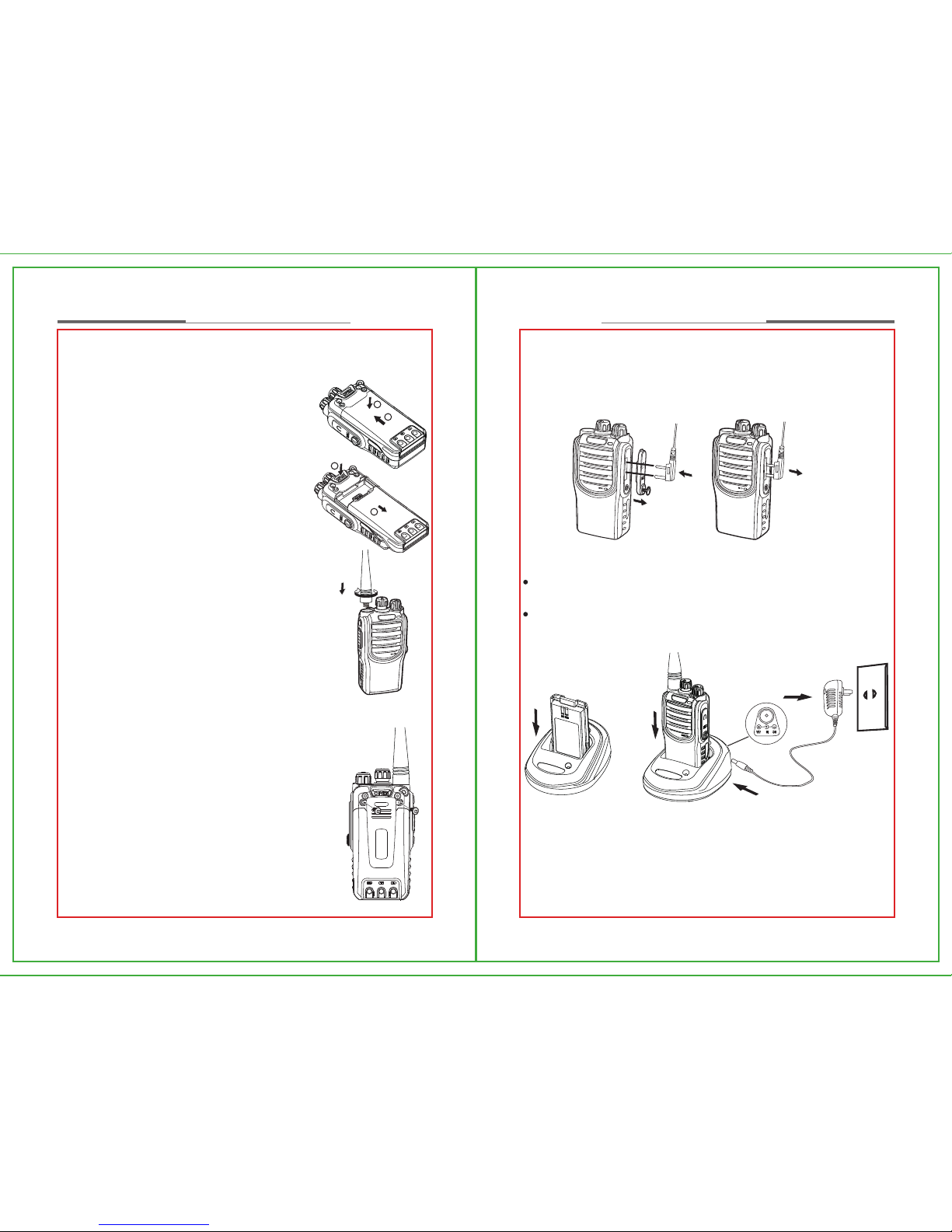
SAFETY INFORMATION
Study this manual carefully to understand your transceiver well.
For safety reasons, it is important that the user is aware of and
understands the potential hazards common to using any transceiver.
To clean the radio, wipe with a soft cloth dampened with water. Never use
solvents or cleaners on the radio, they can harm the body and leak inside,
causing permanent damage.
Your radio is not splash proof or waterproof. If the radio gets wet, turn it
OFF and remove battery immediately. Dry the battery compartment to
minimize potential water damage. Leave cover off battery compartment
and do not use until completely dry.
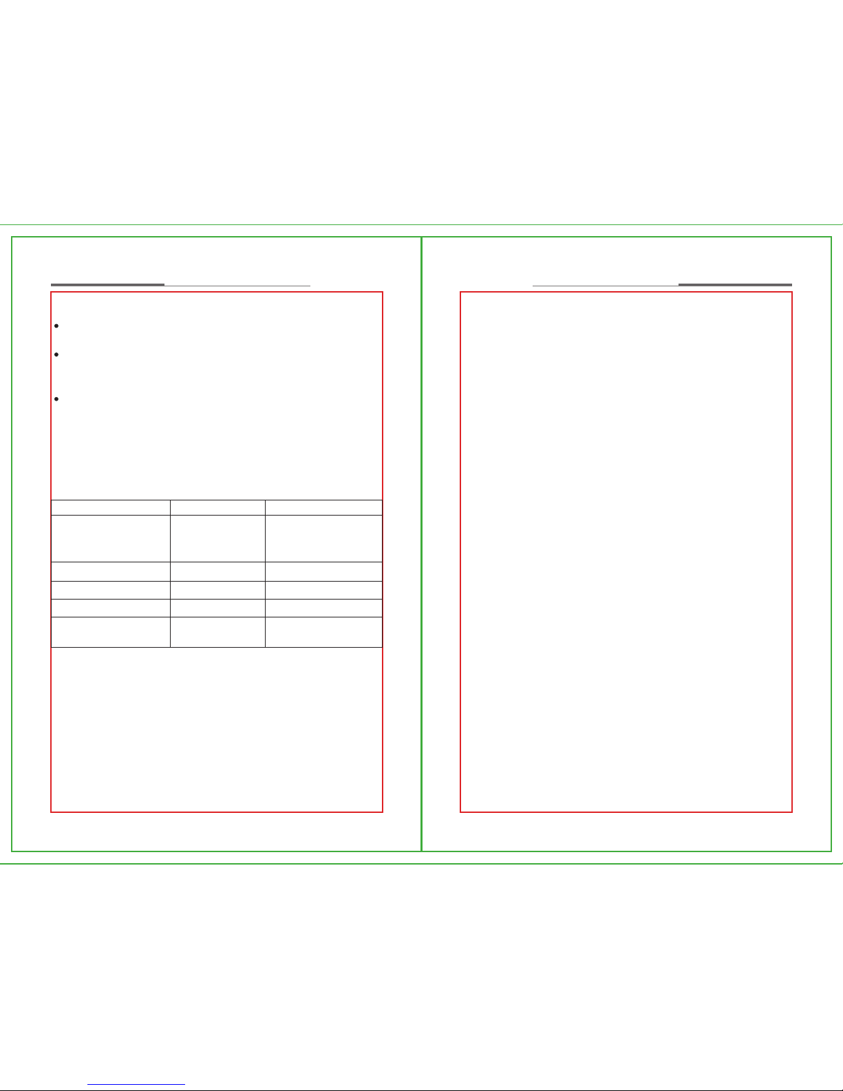
Handle the radio with care and never hold the radio by the antenna. Do
not drop or impact the radio as it contains sensitive electronics.
Do not operate the transceiver or replace/charge the battery in an
explosive environment (dust, gas, fumes etc).
Switch the transceiver off whilst filling gas or when parked at a petrol
station.
Do not open or modify the transceiver in any way.
Refer to a qualified technician for any service or repairs.
Do not expose the transceiver to long periods of direct sunlight, extreme
hot environments or surfaces.
Do not place the transceiver in excessively dusty, humid, wet and/or
unstable areas.
Please turn off the radio when you are close to a blast area or detonator
zone.
Do not use any radio which has a damaged antenna. It may cause a minor
burn when the damaged antenna touches your skin.
To avoid the problems caused by EMI and EMC, turn off your radio where
notices “Please turn off your radios” are posted, such as hospitals.
Turn off your radio before boarding an aircraft. Any use of the radio must
be in accordance with airline regulations or flight crew’s instructions.
If a vehicle is fitted with an air bag, do not place the antenna of the radio
within the air bag expand area.
When the portable radio is transmitting, hold the radio in a vertical position
and speak into the Microphone.
If you carry a radio on your body, please keep the antenna away from
your body by at least 2.5cm when transmitting.
CH Freq Tone
number number
1
2
3
4
5
6
7
8
9
10
11
12
13
14
15
16
1
2
3
4
5
6
7
8
1
2
3
1a
2a
3a
4a
5a
10
10
10
10
10
10
10
10
OFF
OFF
OFF
15
15
15
15
15
Table of programmed
channels

ZA-725 User Manual
04
ZA-725 User Manual
03
BATTERY INFORMATION
Initial Use
New batteries are not charged fully in the factory. Please charge the battery
for 5 hours at least before first use. This initial charge pre-conditions the
battery for full capacity. Failure to charge fully may shorten the life span of
the battery. Recharge the battery immediately once it goes flat as it could get
damaged if left very flat for long periods. The maximum battery capacity and
performance is achieved after three full charge-discharge cycles.
Battery Pack
Please only use a battery which is approved by the manufacturer.
Unauthorized batteries may cause failure of protection circuitry and result in
bodily injury and property damage.
Safety Information
1)Do not throw the battery into fire!
2)The battery should be recycled and disposed of correctly.
3)Never attempt to disassemble the battery pack.
Notices
1)Only charge the battery, when the ambient temperature is
between 5℃- 40℃.
2)Please turn off the radio when the battery is charging. Using the
radio during charging will affect the normal charging of the
battery pack and will lengthen the charge time.
3)During charging, do not plug in/pull out the power supply or the
battery frequently, it would affect battery charging.
4)Do not charge when the battery or radio is wet. Please dry it with
a soft cloth before charging.
5)Do not use the charger, cable or battery if it is damaged, cracked
or frayed in any way.
The battery life is over when the operating time is obviously shorter
than normal even if it’s fully and correctly charged. Please then
replace
two-way radio dealer. The supplier and manufacturer take no responsibility if
a user operates the transceiver not in accordance with ICASA regulation.
Please refer to the sections in this manual for instructions on programming
and the functions available.

ZA-725 User Manual
06
ZA-725 User Manual
05
STANDARD ACCESSORIES
Carefully unpack the transceiver. We recommend that you identify the items
listed below before discarding the packing material. If any items are missing
or have been damaged during shipment, contact the supplier immediately.
For optional accessories, please visit our website www.zartek.co.za
Radio Unit Antenna Battery Charger
Adaptor Belt Clip Hand Strap User Manual
Note: Pictures are only for your references; please take the real objects as
standard!
To Prolong Battery Life
1)Battery performance will degrade when the current temperature is below 0
℃. A spare battery may be necessary in cold weather. Please keep the
cold batteries, as these batteries will work under room temperature.
2)If the battery contact is dusty, it may influence its normal use or normal
charge.
Battery Storage
1)Fully charge a battery before storing for a long time, to avoid battery
damage caused by over-discharge.
2)Recharge the Li-Ion battery after 6 months as the battery will lose small
amounts of charge even when not in use. This regular maintenance will
avoid the battery capacity reducing which is caused by over-discharging.
3)When storing your battery, keep it in a cool and dry place under room
temperature.
No.
1
2
3
4
Items
Main Unit
AC Adaptor & Charger
Li-ion Battery Pack
Antenna
QTY
1
1
1
1
No.
5
6
7
8
Items
Belt Clip
Screws
Hand-Strap
User Manual
QTY
1
2
1
1

ZA-725 User Manual
08
ZA-725 User Manual
07
RADIO OVERVIEW
No.
1
2
3
4
5
6
7
Unit
Antenna
LED Indicator
Speaker
MIC
Channel Selector Knob
Power / Volume Knob
Side Key 1 (SK1)
Remarks
Transmit/Receive signals, detachable for
external antenna options
Receiving: Green Light ; Transmitting: Red
Light
Microphone
Turn the knob to select the channels from
1-16.
1.Turn clockwise to switch on the radio, and
counter-clockwise until a “click” is heard to
switch off the radio.
2.After switching on the radio, turn the knob
clockwise to increase volume, and turn
counter-clockwise to decrease volume.
Press SK1 or SK2 key to enable the specific
function which has been programmed via
software. Press this key to activate the
function (1 Beep) and press again to
deactivate (2 Beeps). SK1 is factory set on
Monitor (short press) & Call Ring (long
press)
No.
8
9
10
11
Unit
PTT (Push-To-Talk) Key
Side Key 2 (SK2)
SP/MIC Jack
Battery Pack
Remarks
Press and hold the PTT key to transmit, and
release it to receive.
SK2 is factory set on VOX (voice activation /
hands-free) short press
Dustproof and Rainproof
1
2
3
4
5
6
7
8
9
10
11

ZA-725 User Manual
10
ZA-725 User Manual
09
Install & Remove the headset / programming cable
Open (unscrew) the SP / MIC cover and then plug in the accessory firmly into
the side jack.
If you want to remove the accessory, unplug it gently and close the SP/MIC
cover.
Charging the Battery
When the battery capacity runs low, the radio’s red LED will begin to flash
and a voice message “Please charge the battery” will be heard.
Only use the charger docking station and AC adaptor supplied with the
radio. The battery can be charged whilst it is fitted to the radio or simply on
its own as depicted in the sketch below.
Setup:
Please follow these steps:
1.If the battery is to be charged whilst fitted to the radio, please ensure that
the radio is switched off.
2.Connect the adaptor cable to the back of the desktop cradle.
3.Connect the adaptor to the AC power socket.
4.Insert the radio or the battery into the charger cradle. The Red and Green
LEDs will flash briefly.
GETTING STARTED
Install & Remove the Battery
Installing Battery Pack
Align the battery pack with the grooves on the back
chassis of the radio.
Slide the battery pack along the chassis until it fits into
the top groove with a “Click”.
Removing Battery Pack
Push the battery pack latch inwards to unlock and
release the battery.
When the battery pack is released from the groove,
push the battery pack downward and remove it.
Install & Remove the Antenna
Install the Antenna
1.Switch off the radio; insert the threaded end of the
antenna into the antenna connector on the top of the
radio.
2.Screw down the antenna clockwise until it is secure.
Remove the Antenna
Switch off the radio then turn the antenna
counter-clockwise to remove.
Install & Remove the Belt Clip
Install the Belt Clip
Remove the battery off the radio. Line up the holes of
the belt clip with those on the radio and insert both
screws. Tighten clockwise using a screwdriver until
secure.
Remove the Belt Clip
Unscrew both screws from the holes and remove belt
clip.
①
②
1
1
2
2

ZA-725 User Manual
12
ZA-725 User Manual
11
recharge when getting flat. If an almost full battery is recharged, the
charging cycles are not optimized.
3. When the battery charge goes flat, the radio’s LED will flash a red light
and the radio will keep reporting “Please charge the battery”.
5.The following LED display sequence will now show the status of the
charging process as depicted in the table below:
Continuous Red LED indicates that the battery is being charged. The
charging process will approximately take 5 hours.
When the battery is fully charged, the Red LED will change to a green LED
which will be ON continuously. Remove the AC power supply from the
charger pod or remove the Radio / battery from the cradle.
If the Red LED keeps flashing, the battery voltage is below 6V or the
battery could be damaged. If the battery voltage is below 6V, the battery
will eventually begin to charge after some time and the status of flashing
Red LED will change to being continuously ON. If however, the battery is
damaged, the status of the flashing Red LED will not change.
Charger Status
NB Overcharging a battery can reduce its life. It is advisable to stop the
charging process when the green LED comes ON.
CHARGE TIME is approximately 5 hours from flat to full.
OPERATING TIME is approximately 30 hours with a fully charged battery if
used typically on a 5:5:90 duty cycle.
Note:
1. Make sure the radio is switched off during charging or the charging time
will be longer.
2. Li-ion batteries do not have memory so they can be recharged at any time.
There are a limited number of charge cycles that the battery can handle,
typically 500-700 times. To get the maximum use of the battery only.
LED Status
Red and green light flash
for 1 second, then will go
out.
Red light continuously
Green light continuously
Red light flash
Charger Pod Status
Power on
Standby Mode
Charging Mode
Full Charging
Fault
Remarks
No battery in charger
Battery voltage is lower
than 6V or damaged.

ZA-725 User Manual
14
ZA-725 User Manual
13
The ZA-725 uses the UHF (Ultra High Frequency) band and will be subject to
similar obstacle interference as cellular phones. The radio works indoors as
well as outdoors. Typical rough estimate ranges for different terrains are:
Indoors or Shopping centre 300m-1200m
Building 5-30 stories,
City centre & dense bush 500m-2km,
Residential & over water 2-6km,
Farmland 3-7km,
Top of mountain or building (line-of-sight) 10-30km.
When you press the PTT talk button a signal is transmitted and the signal
floods the area in all sideway directions. The signal travels in 3 different
ways:
1) Penetration: The signal can go through materials such as wood, plastic,
cement and fabric. The denser the material or more built up the environment
the weaker the signal will become. The signal cannot go through solid metal
or very large solid land structures such as a hill or mountain. Metal acts like a
shield and that is why the performance from the inside of a vehicle (car or
4x4) will be less than outside and a external car antenna kit is recommended
to improve communication.
2) Reflection: The signal cannot go through metal or very large structures
such as a hill or mountain, but it can bounce off (like a mirror), go around and
reflect in other directions as well. This happens at the speed of light.
3)Line-of-sight: Line-of-sight is when there are no obstructions in the path
between the communicating parties. The higher up you go the further you
can see, so the larger the line-of-sight distances will be. Generally you can
talk to wherever you can see, which is why the coverage in a valley is much
less than the coverage from on top of a hill.
Ensure that there is nothing blocking the antenna. The less metal in close
proximity (0-2m) the better the range. There may be external interference
from electrical equipment (power lines or factories) or natural causes
(moisture in the air or storms) that may vary depending on the location and
the weather.
BASIC OPERATION
Power On/Off
Turn the Power Knob (also called Volume Knob)
clockwise to switch on the radio; you will hear a “di”
sound and a voice message will indicate the current
channel number. Turn counter-clockwise to switch off the
radio. (see Figure1)
Adjust the Volume
Press the programmed SK1 “Monitor” key or “Squelch
Off” key to listen the background noise, then turn the
knob to increase or decrease the volume. (see Figure2)
Select a Channel
Turn the Channel Selector Knob to select your desired
channel. If the Voice announcement function is enable,
your radio will automatically report the channel No.
where the knob locates. (see Figure 3).
Refer to the factory channel settings when linking your
radio to other radios as it may be necessary to
reprogram or adjust the frequency / sub tone to match.
Transmit
Keep pressing down the PTT key and speak directly into
the microphone (MIC). Hold the radio about 2.5cm to
5cm from your mouth. (see Figure 4). The radio should
be held so that the antenna is vertical.
Receive
Release the PTT key to receive a call and adjust the
volume if needed.
Communication Range
Range will depend on the type of terrain that you are
communicating across.
Figure1
Figure2
Figure3
Figure4

ZA-725 User Manual
16
ZA-725 User Manual
15
PROGRAMMING (OPTIONAL)
A programming cable is needed to program different channels or functions on
the ZA-725. The programming cable links the radio to USB port on a PC or
laptop.
USB installation:
USB cable driver software for your computer operating system is available
for free downloading from www.zartek.co.za or from the cable manufacturer
website Prolific (driver for PL2303 USB-Serial cable). Install the correct
software and plug-in the cable to the PC. The computer should locate the
cable and configure it automatically. You can check that the cable is working
by locating it in DEVICE MANGER > PORTS > PROLIFIC USB – SERIAL
COMM PORT.
Software installation:
Programming software for the ZA-725 is available for free download from
www.zartek.co.za . Install the software on to a PC by following the installation
steps. Once installation is finished, an icon called “ZA-725 User PC
Software” will appear on the screen.
Connect the USB cable to the PC and plug-in the twin connector into the
speaker/microphone jack on the side of the ZA-725 radio. Ensure that there
is a charged battery connected to the radio and switch the radio on. Start the
program and a window will appear. The software automatically finds the
correct port of the programming cable.
Reading data:
Click on the “READ” left icon (arrow away from radio) and press “OK” to
begin reading the data from the radio. The RED LED on the radio will flash
as data is being read. Once loaded, the data can be edited to the appropriate
channels and settings and then saved or printed for future reference. See
below for instructions on each function.
Writing data:
After data is entered, click the “WRITE” right icon (arrow towards radio) to
program the radio. Press “OK” to begin writing the data to the radio. The
GREEN LED on the radio will flash as data is being written. Once finished,
switch the radio off and unplug the cable from the radio. Additional radios can
be programmed by plugging in the cable to the radio, switching it on and
following the “WRITE” procedure.
Licence-free bands:
The RX Freq. (MHz) column refers to the frequencies that can be selected on
the radio. The 8 frequencies in the 446MHz band are represented by the 8
channel numbers, 1-8, in the table. These channels correspond to the
channels on other 446MHz license free radios, such as the Zartek Pro8. The
5 frequencies in the 464MHz band are represented by the 5 channel
numbers, 1a-5a, in the second table. These channels correspond to the
channels on other 464MHz license free radios, such as the Zartek Pro5 or
ZA200 (model# 21-1860-AF).
Ch Freq. (MHz)
1 446.00625
2 446.01875
3 446.03125
4 446.04375
5 446.05625
6 446.06875
7 446.08125
8 446.09375
Ch Freq. (MHz)
1a 463.975
2a 464.125
3a 464.175
4a 464.325
5a 464.375
Code # (Hz) Code # (Hz) Code # (Hz)
1 67.0 14 107.2 27 167.9
2 71.9 15 110.9 28 173.8
3 74.4 16 114.8 29 179.9
4 77.0 17 118.8 30 186.2
5 79.7 18 123.0 31 192.8
6 82.5 19 127.3 32 203.5
7 85.4 20 131.8 33 210.7
8 88.5 21 136.5 34 218.1
9 91.5 22 141.3 35 225.7
10 94.8 23 146.2 36 233.6
11 97.4 24 151.4 37 241.8
12 100.0 25 156.7 38 250.3
13 103.5 26 162.2
Table of 38 quiet tones

ZA-725 User Manual
18
ZA-725 User Manual
17
PROGRAMMABLE SIDE KEYS
You can program specific functions for SK1 & SK2 keys via software. Press
the key to activate/deactivate the function. A single beep sound “di” will
indicate that the function is active and a double beep sound “di di “ will
indicate that the function is deactivated.
The functions can be programmed as follows:
Sub-tones:
The CTC/DCS DEC column shows the sub tone assigned for each frequency.
There are 50 QT (CTCSS quiet tones) and 104 DQT (digital quiet tones that
can be selected. This effectively gives the user 2002 ((8+5)x(50+104))
channels to communicate on. These tones are used to privatize
conversations and reduce interference from other users on the same
frequency. There are 38 CTCSS standard tones (1-38) plus 12 extra QT
tones and 104 digital codes. The 38 tones are common on other 446 &
464MHz radios such as the Zartek Pro8 or Pro5. If the tone is left “OFF”, the
frequency is left “open” to receive communication from any tone, but your
transmitter will not be decoded by a radio with a tone.
No.
1
2
3
4
5
6
7
8
9
10
11
12
Items
OFF
Monitor
Momentary
Scan
VOX
Show Battery
Call Ring
Emergency Alert
Channel
Announcement
PTT ID
Squelch Level
Compander
Scrambler
Remarks
No function
The radio will monitor all activity on the
frequency and accept week or coded (QT/DQT)
signals. SK1 is Factory programmed on Monitor
Momentary
Start Scan.
Voice activation is used to operate the radio in
hands-free mode or as a noise / baby monitor.
The radio will begin transmitting when a noise or
voice is heard. SK2 is Factory programmed on
VOX, sensitivity level 7 of 9 with a delay of 1.5
seconds.
Indicates the level of charge remaining in the
battery.
Sends a loud 3 second ring tone to alert other
radios. SK1 is Factory programmed on Call
Ring, Hold in to activate.
Sends a very loud continuous emergency siren
to alert other radios.
Announces the channel number.
Enables or disables the sending of a PTT ID
recognition signal which is preprogrammed
either on the beginning and end of a
transmission.
Indicates the current Squelch Level.
Enables or disables the receiver
compression/expansion technology which
reduces communication noise and amplifies
voice signals.
Enables or disables the scrambler / descrambler
technology where signals are coded for extra
privacy.

ZA-725 User Manual
20
ZA-725 User Manual
19
Squelch Level Checking
Either side key can be programmed to enable this function. When you press
the side key to check the squelch level, the radio will indicate the level 1-9.
There will be no indication if the squelch is at level 0 as it is disabled.
Time-out Timer
The purpose of the Time-out Timer is to prevent any person jamming up a
channel for a long time whilst transmitting. If the time that you continuously
transmit exceeds the set Time-out time, the transceiver will stop transmitting
and a tone “beep” will sound. To stop the tone, release the PTT switch. You
can press the PTT switch again to resume transmitting.
Note: you can set up the time level: OFF, 30s, 60s, 90s …… 300s
Factory programmed on TOT 90s
Tones
Some channels may have pre-programmed CTCSS/QT/DQT tones. A
CTCSS/QT/DQT tone is a sub-audible tone which allows you to ignore (not
hear) calls from other parties who are using the same channel. When you
receive a signal that has a tone different from the one set up in your
transceiver, you will not hear the signal. Likewise, signals that you transmit
will only be heard by parties whose CTCSS/QT/DQT tone matches the tone
set up in your transceiver. There are 38 standard CTCSS tones (see table for
allocated tones), 12 QT and 104 DQT which can be selected per channel.
Note: Although using channels set up with CTCSS/QT/DQT tones relieves
you from listening to unwanted calls; it does not mean your calls will be
totally private.
Scan
Either side key can be programmed to activate / deactivate this function. The
scan function is useful when you want to find other people on similar
frequencies or to monitor communication within your group. If an active
channel is found the scan will stop and lock on to that channel. You can now
transmit and receive on this frequency. When the signal is gone for 5
seconds, scanning will resume. The radio will announce which channel of the
possible 16 programmed channels has been received. This is very useful
when monitoring a large number of channels and responding to the correct
channel.
AUXILIARY FUNCTIONS
The functions below can be programmed in software. Some of the functions
have been switched off before leaving the factory and may need to be
programmed if required.
Battery Save Function
The Battery Save function decreases the amount of power used when a
signal is not being received and no operations are being performed (no keys
are being pressed, and no switches are being turned). While the channel is
not busy and no operation is performed for 12 seconds, Battery Save turns
ON. When a signal is received or an operation is performed, Battery Save
turns OFF.
Factory programmed on Save On
Beep Tone
A beep tone is sounded when the radio is switched on or the side buttons
presses to activate / deactivate function. If the beep tone is unselected there
will be no beep when switching on or pressing side keys.
Factory programmed on Beep enabled
Squelch
The squelch level is used to adjust the threshold at which signals will open
the audio channel. A low level will allow weaker signals to be audible,
although with more background noise. However, if weak signals are
annoying, the level can be adjusted higher to open the channel only when
stronger signals are received.
You can set up the squelch level from 0 to 9. The higher the squelch level,
the less noisy is the signal as only stronger signal are accepted. The lower
the squelch level the noisier the signal is, as weak signals are also allowed.
As the communication range or obstructions between radios increase, the
weaker the signal becomes. It is advised to use a lower squelch level to get
further communication range.
Level 0 will disable the squelch function and the radio will receive all
background noise on that frequency at all times. You can set up the
appropriate squelch level via software according to the current
communication environment and requirements.
Factory programmed on Squelch level 5

ZA-725 User Manual
22
ZA-725 User Manual
21
Monitor Momentary
The squelch circuit on the transceiver mutes the speaker automatically, when
no signals are present. So you will not hear background noise. Press the
Monitor key to deactivate the squelch manually. This is useful when you want
to adjust the volume level, or when you need to hear a weak signal. Monitor
Momentary will remove squelch so all background noise will be heard and all
tones (QT/DQT) accepted on the same frequency.
The LED indicator lights green while the radio is in Monitor mode.
SK1 is Factory programmed on Monitor Momentary
VOX (Voice-operated Transmission)
The ZA-725 has innovative state-of-the-art technology not seen in other
two-way radios with its multi-level sensitivity built-in VOX function. You can
enjoy talking and listening without pressing PTT key as transmit is
automatically activated by sound. This turns your radio into hands-free “walk
& talk” when used with a headset. Voice activation is used to operate the
radio in hands-free mode or as a noise / baby monitor. The radio will begin
transmitting when a noise or voice is heard. Ensure that you speak directly
into the microphone of the radio at a distance of less than 5cm. There are
many headset options (see optional accessories below) which can be used in
VOX mode allowing for full hands-free communication.
VOX level
The sensitivity level of the microphone can be adjusted to allow different
volumes of sounds to make the radio begin and remain transmitting. There
are 1-9 levels with 9 being the highest and most sensitive to lower volumes
of sound. If the radio is used in a very noisy environment it is recommended
to use a low sensitivity level to avoid the radio transmitting unnecessarily. At
low sensitivity level it will be required to speak loudly into the microphone to
activate the radio. At high sensitivity, a soft voice is all that is required.
VOX Delay time
Once the radio senses a voice and begins transmitting it is possible that the
volume of the voice is lowered or there are pauses in the message which
may cause the radio to stop sending. A VOX Delay time (0.5-3S) will keep the
microphone active for the set time before returning to receiving mode. This
Priority Scan
Normal scan will sequence through all the channels in
order until a signal is detected. Priority scan allows one
channel to be checked more often which is useful when
there is one main or more busy channel.
For example: If CH2 is set as a priority channel. So the
scan method will be:
Normal scan is CH1, CH2, CH3, CH4……According to
the sequential scan.
Priority scan is CH1, CH2, CH3, CH2, CH4, CH2……
checks same channel in between others.
Scan Modes
There are two modes of scanning depending on the user’s type of
communication.
Carrier: Scan will stop and lock when a signal is received and continue
scanning after the signal has gone for 5 seconds.
Time: Scan will stop when a signal is received and continue scanning 5
seconds later.
Scan Add/Delete
You can add a channel to the scan group or delete it from group.
Add choose Yes in the channel row under the Scan Add column to add the
channel.
Del choose No in the channel row under the Scan Add column to remove the
channel.
Password Protecting Programming
The programming of the radio can be protected using a 6 digit software
password. Once a password is programmed and written to a radio, the user
must enter the password in the software before being able to read the radio.
If the password is forgotten, you must contact your dealer to reset it. It is still
possible to overwrite the programming as normal as no password is required
when writing only when reading.
CH1
CH2
CH3
CH4
CH2
CH2
CH2CH2
CH2
CH1
CH3
CH4
CH5
CH6
CH5
CH6

ZA-725 User Manual
24
ZA-725 User Manual
23
Factory programmed on English.
PTT ID
Each radio can be allocated with a 15 digit ID consisting of digits 0-9 or
A,B,C or D. The PTT ID recognition signal can be set per channel or the side
key can be programmed to activate / deactivate it. The radio can be
programmed to send the ID either at the beginning and/or end of a
transmission. The PTT ID or automatic number identification (ANI) is used to
connect with a repeater or telephone system, or for a control centre’s
communication management to identify this caller’s ID using other radios
equipped with a DTMF Decode function.
Begin of Tx: The radio will send out the ID first before allowing voice
communication once the PTT key is pressed.
End of Tx: The radio will send out the ID at the end of a communication once
the PTT key is released.
Both: The radio will send out the ID first before and after the PTT key is
pressed.
Scramble
Scrambler can be set per channel or the side key can be programmed to
activate / deactivate it. Scrambling technology use a coded algorithm to
invert the audio signal and make it unintelligible unless the other radio also
has the same descramble function. This function is used to achieve extra
privacy on the same channel.
Compander
A compander can be set per channel or the side key can be programmed to
activate / deactivate it. The compander will make communication more clear
by improving the ‘Signal to Noise Ratio’ using compression and amplification
technology and decrease the noise when receiving a signal.
Power Selection (only in dealer license version)
Maximum communication range is achieved when the transceiver is set to
high power mode, whilst lower power settings will save battery life. The
power can be set on low (500mW) or High (4W).
Factory programmed on low 500mW.z
delay time can be chosen to suit your style of speaking and avoid the
message breaking up.
SK2 is Factory programmed on VOX, sensitivity level 7 of 9 with a delay
of 1.5 seconds.
Battery Capacity Indication
Either side key can be programmed to enable this function. The remaining
charge on the battery will be voice indicated using a number 1-4. This is
useful in determining when to charge the radio.
4 – Half to Full 100-40%
3 – Medium 39-30%
2 – Semi-low 29-20%
1 – Low 19-0%
Low Battery Alert
When the battery capacity is getting low and indicates a level of “1”, the radio
will alert you with a message “please charge the battery” every 5 seconds
unless the radio is recharged.
Note: If the Voice Announcement function is disabled, the radio will sound a
double beep “di di ” sound when going flat.
Call Ring
The side key can be set to transmit a loud 3 second call ring tone to alert
other radios.
SK1 is Factory programmed on Call Ring, Hold in to activate.
Emergency Alarm
Either side key can be programmed with a siren alert as an emergency
notification. When pressed, the siren will be sounded on both the sending
and receiving radios. The siren will stop once the side key is pressed again,
the sending radio is switched of or the time-out timer limit is reached.
Announce Voice Channel
As the channels are changed, a voice announces the specific channel. This
is useful when using the radio at night. Either side key can be programmed to
activate / deactivate this function.

ZA-725 User Manual
26
ZA-725 User Manual
25
Busy Channel lock out (only in dealer license version)
The transceiver can be programmed with channel lock-out. When set, this
function will disable the PTT button from transmitting if there is any activity
on the same frequency with a different QT/DQT tone. This prevents
interference in community repeater systems.
Factory programmed on BCLO off
OPTIONAL ACCESSORIES
EXTERNAL ANTENNA KIT
A main feature on the ZA-725 radio is the detachable antenna. An external
antenna can be connected to the radio and improve radio clarity and range
when using the radio in a vehicle or building. Radio signal strength is
reduced by metal and concrete enclosures. When the antenna is placed
outside the signal propagation and clarity improves significantly.
Communication range is approximately doubled when using the car external
antenna. Also note that, the higher the antenna is placed, the further the
range.
GE-295 car kit consists of a magnetic mount rain-proof antenna with cable
and car charger.
GE-263 house kit for buildings includes an “L” bracket antenna mount with
8m cable
HEADSETS (use with PTT or VOX)
GE-252 Earphone speaker with in-line PTT microphone
GE-259 Lapel speaker microphone for vehicle & security use
GE-266 Acoustic eartube speaker with microphone for discrete
communicationGE-273 Heavy Duty D-Cup high volume speaker with mic. &
in-line PTT
GE-273 Heavy Duty D-cup high volume speaker with boom mic. & in-line
PTT
GE-276 Throat Microphone with lapel & finger PTT for motorbike & high
wind/noise
GE-296 Spare Battery (7.4V 1100mAH)
GE-251 Carry pouch with detachable shoulder strap
GE-254 PC Programming cable USB
GE-297 Desktop Cradle Charger (12V DC)
GE-298 Vehicle DC adaptor (12V output)
LM-513 Mains adaptor (12V output)

ZA-725 User Manual
28
ZA-725 User Manual
27
TROUBLESHOOTING SPECIFICATION
Problem
No power.
Battery power dies shortly
after charging.
Cannot talk to or hear
other members in your
group.
Other voices (besides
group members) are
present on the channels.
The transceiver
continuously rings
Solution
The battery pack may be dead. Recharge
or replace the battery pack
The battery pack may not be installed
correctly. Remove the battery pack and
install it again.
The battery pack life is finished. Replace
the battery pack with a new one.
Make sure you are using the same
frequency and QT/DQT as the other
members in your group.
Other group members may be too far
away.
Make sure you are within range of the
other transceivers.
Change the QT/DQT.
Be sure to change the tone on all
transceivers in your group.
Channel programming is empty.
Frequency Range
Channel Capacity
Frequency Spacing
Working Voltage
Frequency Stability
Operating Temperature Range
Antenna Impedance
Dimension excl Antenna
(L×W×H)
Weight (including Antenna and
Battery)
Battery Capacity
Battery Operating Time Average
Output power
Modulation Mode
Maximum Frequency Deviation
Audio Distortion
Residual frequency modulation
Adjacent Channel Power
Spurious and Harmonic Wave
446MHz & 464MHz license-free,
(400-470MHz licensed)
16
25kHz/12.5kHz
7.4V
±2.5ppm
-25℃~ +55℃
50Ω
113mm×57mm×34.5mm
200g
1100mAH
30 hours on 5:5:90 duty cycle
500mW license-free, (4W licensed)
16kΦF3E/8kΦF3E
±5kHz/±2.5kHz
≤5%
-40dB /-35dB
-70dB /-60dB
-36dBm<1GHz -30dBm>1GHz
GENERAL
Receiving Sensitivity
Adjacent Channels Selectivity
Intermediation
Spurious Response
SNR
Audio Output Power
Audio Distortion
≤0.18uV/0.22uV
≥70dB/60dB
≥60dB
≥70dB
≥50/45dB
0.5W
≤5%
RECEIVER
TRANSMITTER
Table of contents
Other Zartek Transceiver manuals