manuals.online logo
Brands
  1. Home
  2. •
  3. Brands
  4. •
  5. ZCL
  6. •
  7. Industrial Equipment
  8. •
  9. ZCL Xerxes MOH User manual

ZCL Xerxes MOH User manual

zcl.com | xerxes.com
1. GENERAL
1.1. These instructions for installation of anchors and straps do not
require a person to enter the hole while installing the anchor straps.
They supplement the Anchoring Tanks Section of the Xerxes Installa-
tion Manual and Operating Guidelines (subsequently referred to as
“Installation Manual”).
1.2. Before beginning the tank installation and installing tank hold-
down straps, read through the entire Installation Manual. Installation
instructions are also laminated onto each tank.
1.3. It is the responsibility of the owner, installer and operator to
comply with all federal, state and local laws, regulations, codes and
safety precautions.
1.4. It is important to follow the procedures and instructions in the
Installation Manual in order to safely and properly install a Xerxes
underground storage tank and accessories. Failure to follow those
instructions will void the tank warranty and may cause tank failure,
death, serious personal injury or property damage.
1.5. Xerxes must authorize, in writing and prior to tank installation,
any variation to, or deviation from, the Installation Manual and the
Man-Out-of-Hole Straps Instructions.
1.6. All correspondence regarding variations must be retained for
any warranty claim to be valid.
1.7. If you have questions or encounter situations not covered in
these installation instructions, contact technical support at Xerxes
Minneapolis, 952-887-1890.
2. ANCHORING TANKS
Failure to follow this document’s instructions on proper place-
ment of hold-down straps, deadmen and anchor slabs may
damage the tank, cause property damage and void the tank
warranty.
2.1. Hold-Down Straps
2.1.1. Only Xerxes straps may be used when anchoring a Xerxes
tank.
2.1.2. The only allowed locations for hold-down straps on each tank
are marked on the tank by the arrowhead symbols .
2.1.3. Straps must be used on all marked hold-down locations.
Do not place straps between ribs (except on 4-foot-diameter
tanks). Failure to properly place straps may result in tank
damage.
2.2. Backfill Material
2.2.1. Xerxes tanks must be installed with backfill material as de-
scribed in the Backfill Material Section of the Installation Manual.
2.2.2. Using other than approved backfill material without prior writ-
ten authorization from Xerxes will void the tank warranty.
2.3. Deadmen
2.3.1. Align the deadmen with the tank.
2.3.1.1. If using Xerxes deadmen, align (within a tolerance of ±1
inch) all anchor points with the marked arrowhead symbols on
the tank.
2.3.1.2. If using deadmen other than Xerxes deadmen, check align-
ment of all anchor points to insure that they are within a tolerance of
±1 inch.
Note: The anchor point must be a minimum of 3 inches over
the top of the deadmen to accommodate the strap hook.
2.3.1.3. Always provide sufficient clearance to allow the deadmen to
be set outside of the tank “shadow.” See Tank Spacing subsection
in the Excavation Parameters section of the Installation Manual. (See
FIGURE 2-1.)
2.3.1.4. The top of the deadmen should be aligned to the bottom of
the tank.
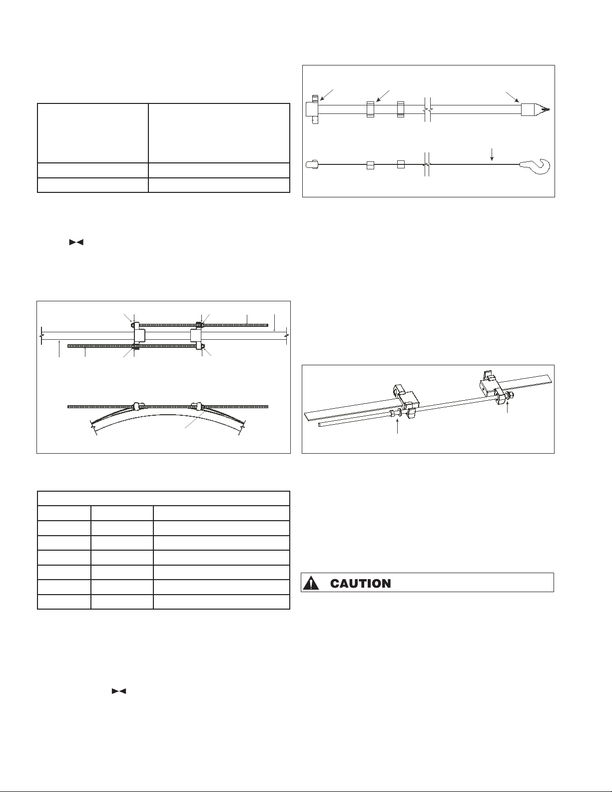
2.3.3. Position the deadmen so they are parallel with the centerline
of the tank. (See FIGURE 2-2.)
2.3.4. Place backfill between deadmen, and level backfill so it is 12
inches deep.
2.3.5. When setting the tank, make sure that the tank is aligned with
the deadmen.
2.4. Anchor Slab
2.4.1. If an anchor slab is used, align (within a tolerance of ±1 inch)
the anchor points on the anchor slab with the marked arrowhead
symbols on the tank.
Tank Shadow
Tank
MOH strap
Anchor Point
Slotted
Deadman
Figure 2-1
Deadman
Strap hook
12” bed
MOH
strap
Load binder
assembly
Figure 2-2
Man-Out-of-Hole (MOH)
Strap Instructions
xmh08/17ih
© 2017 ZCL Composites Inc. ZCL®and Xerxes®are trademarks of ZCL Composites Inc.
zcl.com | xerxes.com
2.4.2. The bottom of the anchor points must be 15 inches above the
top of the slab and positioned the distance from the tank centerline
that is shown in TABLE 2-1.
Note: The straps provided will not work unless the proper
elevation for anchor points is maintained.
Nominal Tank Diameter
Nominal distance
between tank centerline and
anchor point (and tolerance)
8’ 55” (±3 inches)
10’ 72” (±3 inches)
2.4.3. Place 12 inches of level backfill over the slab.
2.4.4. When setting the tank, make sure that the marked arrowhead
symbols on the tank are aligned with the anchor points on the
anchor slab.
2.5. Installing Man-Out-Of-Hole Straps
2.5.1. Each load binder assembly consist of the items shown in
FIGURE 2-3 and TABLE 2-2.
Load Binder Assembly Parts List
Item Quantity Description
1 2 MOH Hold-down strap
2 2 5/8”-diameter threaded rod
3 4 5/8” washer
4 2 5/8” nuts
5 2 5/8” blind nuts (acorn nuts)
6 1 Wear plate
Note: Some contractors prefer to perform Points 2.5.5 through
2.5.7 outside the tank excavation before moving the strap to
the tank.
2.5.2. Clean debris from the top of the tank rib marked with the
arrowhead symbols .
2.5.3. Lift the strap with the hook end down and the hook facing
away from the tank. (See FIGURE 2-4.)
2.5.4. Lower the hook end of the strap between the tank and the
anchor point, and hook the strap to the anchor point.
2.5.5. On one end of the threaded rod, put a washer and a blind nut
(acorn nut).
2.5.6. Feed the rod through the hole in the strap-end connector.
(See FIGURE 2-5.)
2.5.7. On the other end of the threaded rod, put a washer and a nut.
2.5.8. Center the wear plate on the top center line of the marked
ribs.
2.5.9. Lower the threaded rod, washer and nut into the channel
section on the strap-end connector, taking care to place the washer
and nut on the outside of the connector. (See FIGURE 2-5.)
2.5.10. Hand-tighten the nuts.
2.5.11. Repeat POINTS 2.5.5, 2.5.6, 2.5.7, 2.5.9 and 2.5.10 for the
second rod of the assembly.
2.5.12. After the two threaded rods are placed, tighten the threaded
rods, using a torque wrench to tighten to 25-30 foot-pounds, or
until snug.
2.5.13. Repeat POINTS 2.5.2 to 2.5.12 for each of the load binder
assemblies.
When tightening straps, do not cause deflection of more than
3/16-inch to the tank diameter.
2.5.14. Tank deflection should be checked by taking the tank diam-
eter before and after tightening straps as explained in the Deflection
Measurement Section of the Installation Manual.
2.5.15. All exposed metal on the anchoring system must be coated
with a corrosion-protection material. Previously coated metal that
has been damaged must be recoated.
2.5.16. Continue installing the tank according to the Installation
Manual.
Galvanized strap-
end connnector
Alumium
strap guideGalvanized
strap hook
MOH strap
1
2
4
2
4
6
1
33
33
Note: The numbers above correlate to item numbers in TABLE 2-2.
5
5
Table 2-1
Figure 2-3
Table 2-2
Figure 2-4
Add blind nut and
washer here
Add nut and washer here
Figure 2-5

Popular Industrial Equipment manuals by other brands

Siemens FLENDER PLANUREX 2 PBUC Series Assembly and operating instructions

Siemens

Siemens FLENDER PLANUREX 2 PBUC Series Assembly and operating instructions

Radicon A Junior Series manual

Radicon

Radicon A Junior Series manual

Festo YJKP-ST operating instructions

Festo

Festo YJKP-ST operating instructions

WEISS NR Series Mounting instructions

WEISS

WEISS NR Series Mounting instructions

enVerid HLR 100M installation manual

enVerid

enVerid HLR 100M installation manual

SMC Networks C G5 N Series Operation manual

SMC Networks

SMC Networks C G5 N Series Operation manual

Dover DESTACO ROBOHAND DLB Series Service manual

Dover

Dover DESTACO ROBOHAND DLB Series Service manual

goodnature A24 quick start guide

goodnature

goodnature A24 quick start guide

Et 400 Series Bulletin

Et

Et 400 Series Bulletin

ABB HT608520 Operation manual

ABB

ABB HT608520 Operation manual

Schmalz SPZ operating manual

Schmalz

Schmalz SPZ operating manual

Bosch Rexroth HAD 1 Series operating instructions

Bosch

Bosch Rexroth HAD 1 Series operating instructions

ABB HT574657 Operation manual

ABB

ABB HT574657 Operation manual

Coremorrow P77 user manual

Coremorrow

Coremorrow P77 user manual

Siemens SIRIUS 3RV1923 operating instructions

Siemens

Siemens SIRIUS 3RV1923 operating instructions

Jäger Z33-M060.51 K0,15 S15 manual

Jäger

Jäger Z33-M060.51 K0,15 S15 manual

ABB HT570013 Operation manual

ABB

ABB HT570013 Operation manual

STS M2 Series Operator's manual

STS

STS M2 Series Operator's manual

manuals.online logo
manuals.online logoBrands
  • About & Mission
  • Contact us
  • Privacy Policy
  • Terms and Conditions

Copyright 2025 Manuals.Online. All Rights Reserved.