ZDH ZERT Veranda Series User manual

V17/16
Legend Plus & Expert Plus edition
EN AssemblyInstrucons
Veranda

2
Legend Plus & Expert Plus edition
EN - Assembly Instrucons Veranda
Manual for the end user
and the installer
Dear customer,
Thank you for purchasing one of our verandas. This manual
provides all the necessary informaon to quickly become
familiar with the product. We kindly ask you to read this
informaon carefully before working with the product. This
manual is intended for the end user and the installer.
The assembly of the product is described in two chapters:
1. Preparaons for assembly (page 3)
2. Assembly (page 10)
This is the original manual. Keep this manual safe!
Product descripon
The veranda may only be used to cover a terrace. Any
use, other than dened here, is seen as unintended use.
The manufacturer cannot be held responsible for any
(consequenal) damage caused by unintended, improper
or unwise use.
Symbols used
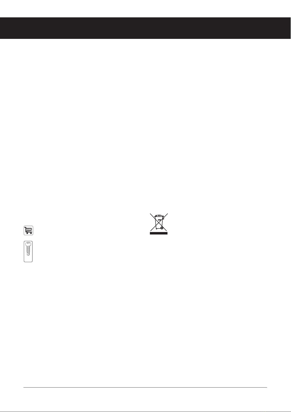
This symbol means that the product is not included
and you have to purchase it yourself.
..x..
(..x)
This symbol means that you must use the supplied
screw. The type and number of screws are shown
underneath.
Environmental condions
This product is intended for outdoor use and may get wet.
Tools required
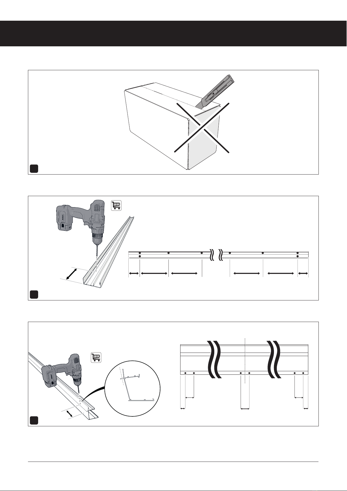
- Stanley knife or scissors
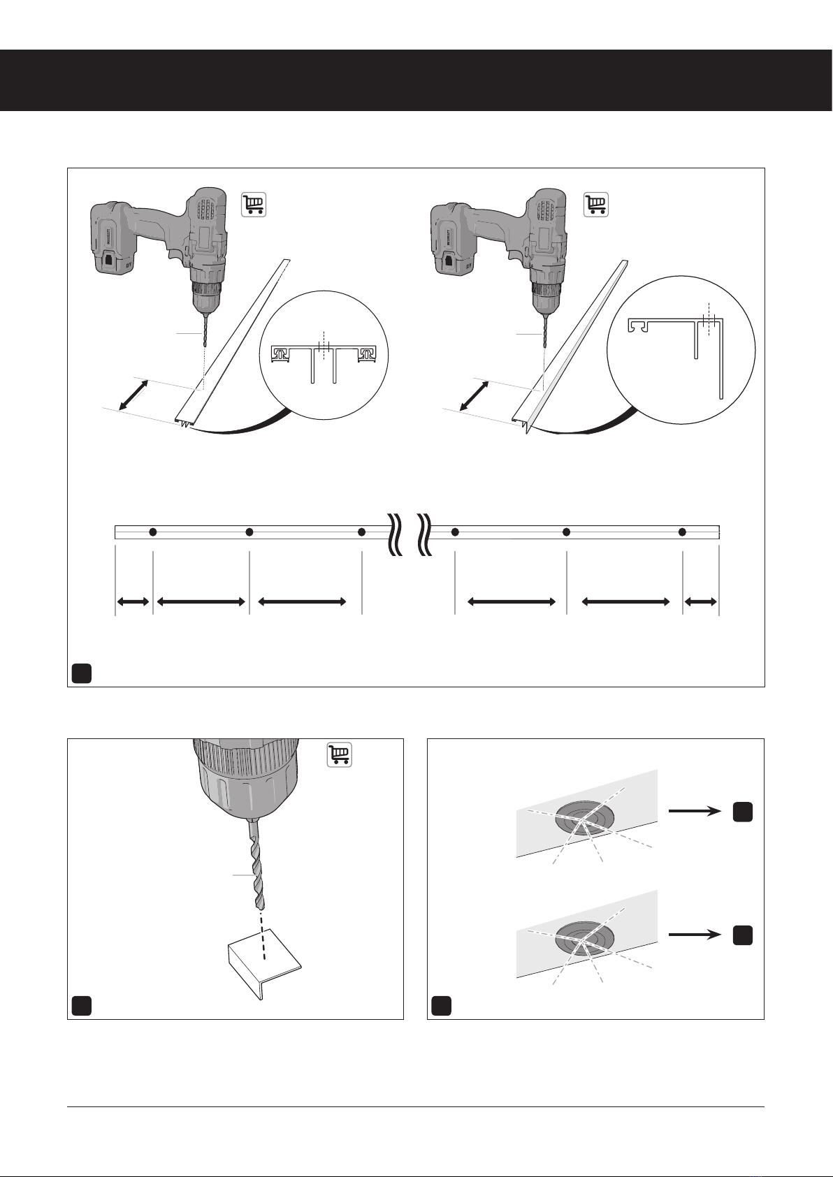
- Drill (5 mm)
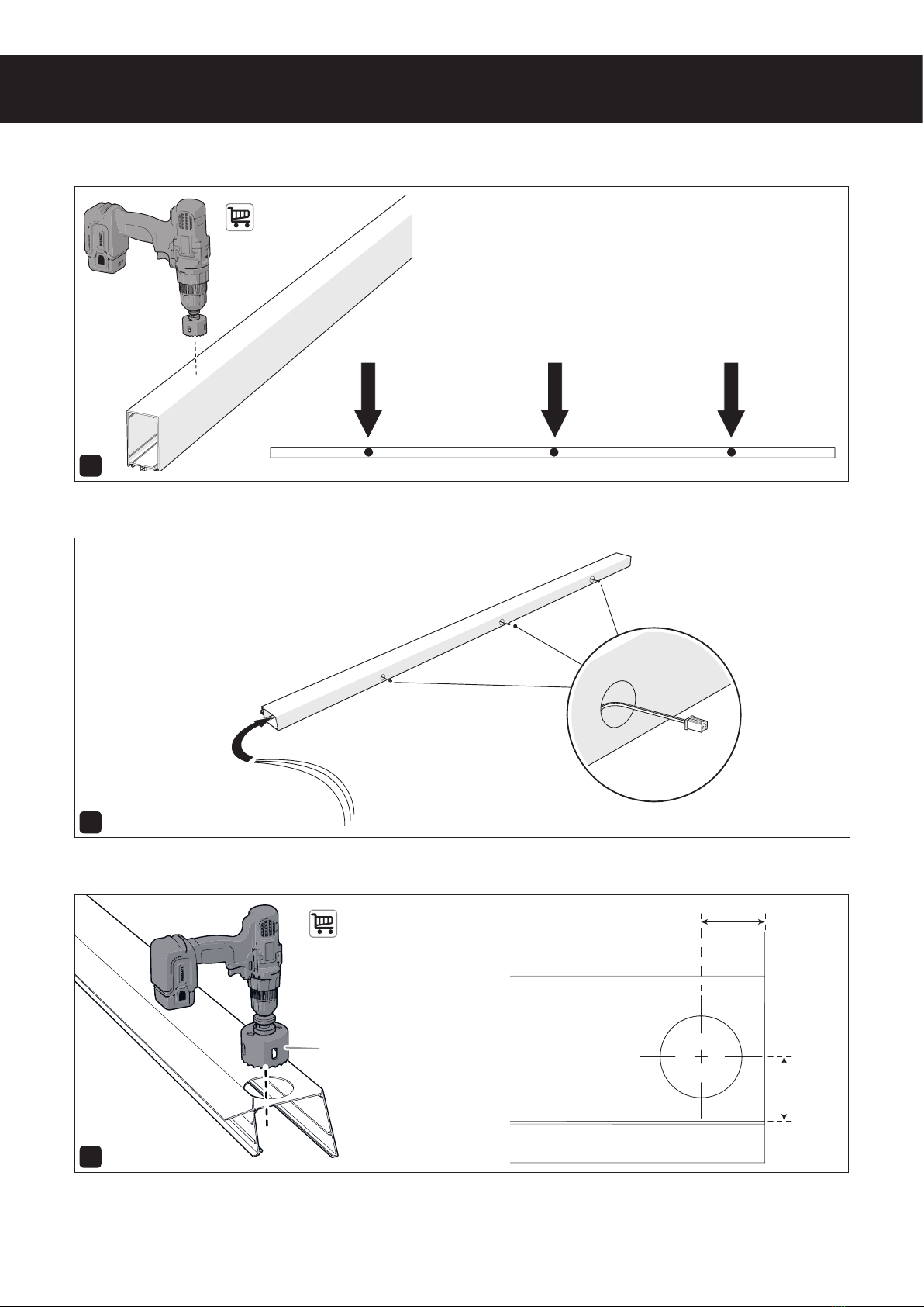
- Holesaw (32mm and 82mm)
- Hacksaw
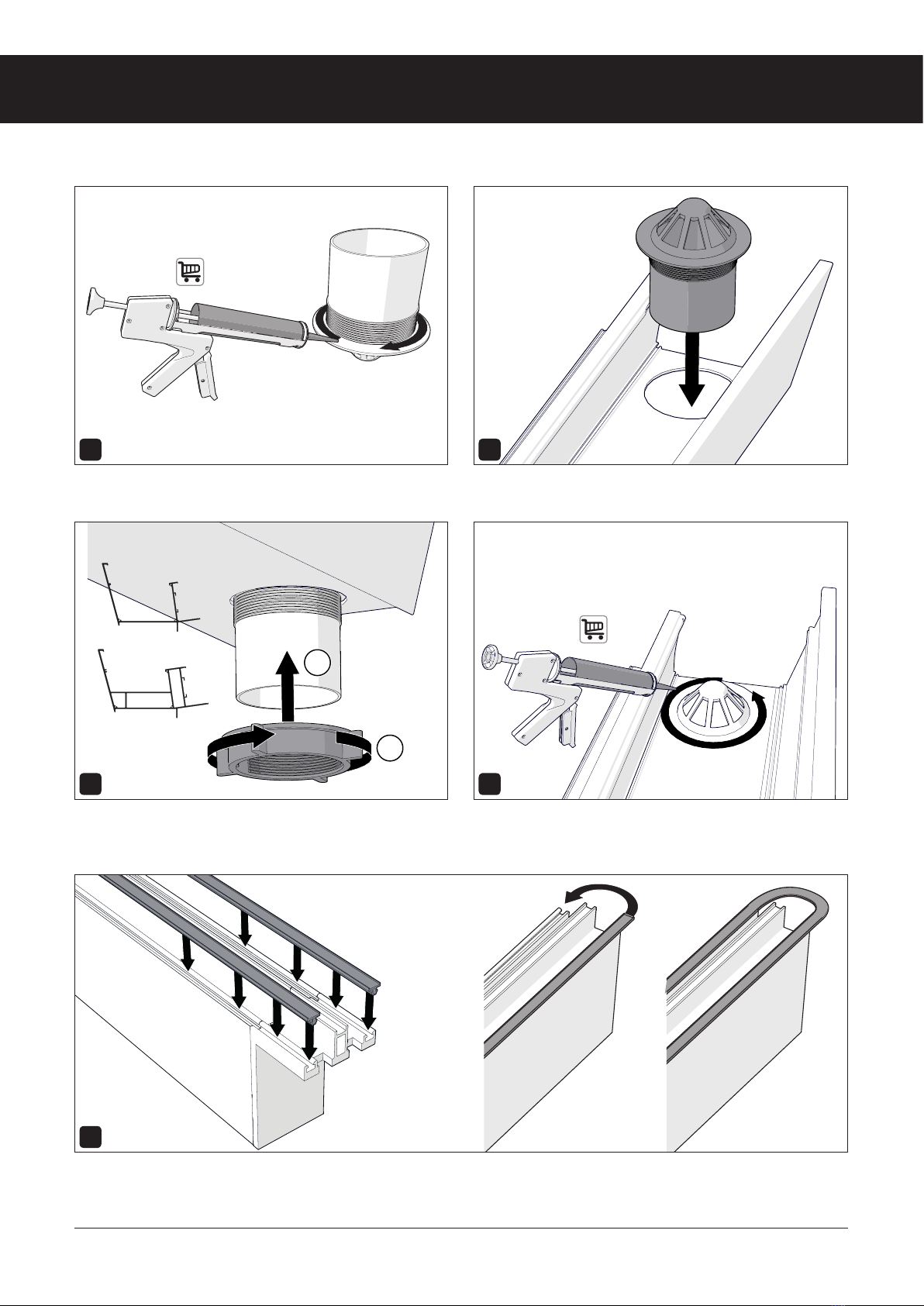
- Cartridge gun with sealant for outside
- Pencil
- Hammer
- Dowels
- Acrow props (2x)
- Shovel
- Spirit level
Precauons and Safety Instrucons
Warning!
• - If your veranda has lighng, the electrical installaon
may only be carried out by a qualied electrical
installaon technician.
• The end user is responsible for the correct installaon
and use of the product. Improper assembly or
improper use may cause damage to, or a defect in, the
product. The warranty is void if the product and/or the
electronic components are damaged through improper
assembly or use.
• Observe local laws and regulaons when assembling
and/or using the product.
Please note!
• Fixing materials are not included, these must be
purchased separately.
• All screws should be carefully ghtened with a torque
of 1.0 Nm.
• Contact your supplier if a part is missing or damaged.
Maintenance, environment and disposal
• Clean the product every 6 months to ensure a longer
product life.
The symbol on the material, the accessories or
packaging indicates that this product may not
be treated as household waste. Dispose of the
device through a collecon point for recycling
waste electrical and electronic equipment within the
EU and in other European countries that have separate
collecon systems for used electrical and electronic
equipment. Properly disposal of the device helps you to
prevent possible environmental and public health hazards
that would otherwise be caused by improper handling of
the waste device. Recycling materials helps to conserve
natural resources. Do not dispose of your old electrical and
electronic equipment through household waste.

3
Legend Plus & Expert Plus edition
1Assembly preparaons
2 cm
Ø 5 mm
7 cm 7 cm
2 cm 2 cm7 cm
10 cm
1
Carefully unpack the product. Do not use any sharp objects to open the boxes.
2
Pre-drill the wall prole according to the mounng xings (not supplied).
3
Determine the desired number of posts and drill two Ø 5 mm holes for each post in the guer prole as shown in the drawing.
10 cm10 cm ±50 cm±50 cm ±50 cm ±50 cm

4
Legend Plus & Expert Plus edition
15 cm
Ø 5 mm
Ø 5 mm
Ø 5 mm
15 cm
Ø 5 mm
Ø 5 mm
15 cm15 cm ±50 cm±50 cm ±50 cm ±50 cm
a
4
Pre-drill the cover proles with a Ø 5 mm drill bit.
Ø 5 mm
5 6
Drill a Ø 5 mm hole at the centre of each
angle plate.
Go to step 7 if you want to install spotlights. Go to step 9 if you
are not installing spotlights.
7
9
X

5
Legend Plus & Expert Plus edition
82 mm
55 mm
55 mm
7
Determine the posion of the spotlights in the beams and drill a maximum of three Ø 32 m holes.
8
Lay the cables for the spotlights in the beams from the wall side.
Please note! Let the cables protrude 10 to 15 cm. Don’t shorten the cables!
9
Drill one Ø 82 mm hole at the end of the guer for the leaf trap.
32 mm max. 3

6
Legend Plus & Expert Plus edition
1
2
1
2
10 11
Place the plasc end piece for the right side on one of the side
beams.
Place the plasc end piece for the le side on the other side
beam.
12 13
Place the plasc end pieces for the intermediate beams on all
intermediate beams.
Unscrew the leaf trap nut.
14
Saw o the protruding parts of the nut.

7
Legend Plus & Expert Plus edition
1
2
1
2
Standard
GIGA
15 16
Apply sealant to the leaf trap. Insert the leaf trap into the guer.
17 18
Tighten the nut onto the leaf trap by turning it anclockwise.
Please note! Glue the leaf trap if you have a GIGA guer.
Apply sealant to the leaf trap.
19
Cut the rubber seals to twice the length of the beam + 10 cm. Push the rubber seals on the wall side with a loop into the beam.

8
Legend Plus & Expert Plus edition
1 cm
1 cm
1 cm
20
Push the rubber seals into all intermediate beams. Cut the rubber seals ± 1 cm longer than the intermediate beams.
21
Push the rubber seals into all the side beams. Cut the rubber seals ± 1 cm longer than the side beams.
22
Push the rubber seals into all the side covers. Cut the rubber seals ± 1 cm longer than the side covers.

9
Legend Plus & Expert Plus edition
1 cm
1 cm
23
Push the rubber seals into all the covers. Cut the rubber seals ± 1 cm longer than the covers.
24
Push the rubber seals into all the click frames. Cut the rubber seals ± 1 cm longer than the click frames.

10
Legend Plus & Expert Plus edition
2Assembly
For construcon possibilies of the Legend Plus Edion (STANDARD guer) with standard length beams see Appendix 1.
For construcon possibilies of the Expert Plus Edion (GIGA guer) with standard length beams see Appendix 2.
1
Determine the desired roof pitch between 5° and 15°. The standard roof pitch is 8 degrees (141 mm fall per meter)
2 3
Determine and mark the mounng locaon of the wall prole.
Calculate the height using the calculaon tables in Appendix 1
and 2 on pages 28 to 31 in this manual.
Mount the wall prole level on the wall. If necessary, place
standard compriband (210 cm, not supplied) behind the wall
prole to ll in any unevenness.
4
Seal the top of the wall prole with sealant.
5°
8°
15°
Y
X
1 m2 m3 m4 m
56 cm
42 cm 28 cm 14 cm

11
Legend Plus & Expert Plus edition
4.2x19
(6x)
5 6
Place the Acrow props and adjust them to the correct height. Place the guer onto the Acrow props.
7
Place a side beam against the side of the guer prole and the wall prole.
8
Mount the side caps with seven screws, use these to mark on the side beam where you want to cut.

12
Legend Plus & Expert Plus edition
4.2x19
(1x)
4.2x19
(1x)
9
Saw along the marked line and break the corners of the side beams with pliers.
10
w
Aach the side beams with one screw to the supplied mounng brackets as shown above.

13
Legend Plus & Expert Plus edition
4.2x19
(7x)
90˚ 90˚
A B=
3
2
1
3
2
1
2
1
3
2
1
3
11
Ret the side caps on the side of the guer and the wall prole with seven screws. Fix the side beam with the middle screw (A) in the
head plate and seal the front side cover at the guer.
12 13
Repeat steps 7-11 for the other side beam. Adjust the veranda so that it is square.
14
Determine the posion of the posts and dig them out.
A

14
Legend Plus & Expert Plus edition
1 m2 m3 m4 m
56 cm
42 cm 28 cm 14 cm
15 16
Install the post foundaon with integrated rainwater drainage pipe
(RWP).
The post foundaon is oponal.
Connect the RWP to the sewer.
17 18
Adjust the guer so that it is level. Determine the length of the RWP post.
19 20
See Appendix 1 and 2 for the falls of your specic setup. Cut the RWP post to size.

15
Legend Plus & Expert Plus edition
xx mm
xx mm
21
Install the coupling sleeve.
22 23
Determine the length of the drainpipe. Cut the drainpipe to size.
24 25
Insert the drainpipe into the post. Place the post with the drainpipe onto the post foundaon.

16
Legend Plus & Expert Plus edition
xx mm
xx mm
4.2x32
(2x)
4.2x32
(1x)
26 27
Li up the guer and allow the leaf trap to drop into the
drainpipe.
Fix the post to the foundaon with two screws.
28 29
Fix the post to the guer using one screw. Determine the height of the other posts.
30 31
Cut the posts to size. Drill two Ø 5 mm holes in the boom of the posts.

17
Legend Plus & Expert Plus edition
4.2x32
(1x)
4.2x32
(1x)
32 33
Place the post foundaons into the posts at the correct distance. Drill holes in the post foundaons.
34 35
Fix the post foundaons using dowels or screws and plugs (not
included).
Place the posts under the guer.
36 37
Fix the post to the guer using one screw. Fix the post to the guer using one screw.

18
Legend Plus & Expert Plus edition
X mm
X mm =
xx mm
38
Determine the center of the porch on the guer and the wall prole.
39 40
Place the rst intermediate beam between the guer and the
wall prole.
Place an intermediate beam on an odd number of roof surfaces
so that there is a half roof panel width from the middle. Place
the intermediate beam with an even number of roof surfaces in
the middle of the veranda.
41
Aach the intermediate beam to the wall prole and the guer using the mounng brackets. Place two mounng brackets on the side
of the wall prole and two mounng brackets on the side of the guer.
4.2x19
(4x)

19
Legend Plus & Expert Plus edition
42
Please note! Only screw the mounng brackets to the beams! There should be no screws in the guer and the wall prole. The beams
should sll be able to slide.
43
Place a second intermediate beam between the guer and the wall prole. The intermediate beam should be placed in such a way that
there is a roof panel width to the rst intermediate beam.
44
Determine the length of the click frames. They can be calculated
like this:
- For glass roof panels: glass width - 30 mm
- For polycarbonate roof panels: panel width -35 mm
Saw the click frames to size and place them between the
intermediate beams on the guer and the wall prole. Slide the
intermediate beams ght against the click frames.
xxx mm
xx mm

20
Legend Plus & Expert Plus edition
2
6
5
1
4
3
2
6
5
1
4
3
45
Aach the click frames as shown in the image.
46
Posion and aach the other intermediate beams and click frames. Slide the intermediate beams ght against the click frames.
47
Saw the outer click frames to the remaining length and place them in the guer and the wall proles.
Please note! Do not place a click frame at the power point yet if you are installing spotlights.
remain
remain
This manual suits for next models
2
Table of contents
Popular Outdoor Furnishing manuals by other brands

Outsider
Outsider PLATEAU Picnic O Mounting instructions

Hanover
Hanover Orleans ORL4PCTFPSW2-BRY manual

Weka
Weka 6-Eck Paradies ASSEMBLY, USER AND MAINTENANCE INSTRUCTIONS

HAMPTON BAY
HAMPTON BAY SAUNTERA FRS80750-ST Use and care guide

HAMPTON BAY
HAMPTON BAY GC-8896-SST Use and care guide

HAMPTON BAY
HAMPTON BAY FWS80486BG Use and care guide

Members Mark
Members Mark Halstead GC-11557-7PC Assembly instructions & user manual

HAMPTON BAY
HAMPTON BAY GG-11110-AAA Use and care guide

Factoryfurniture
Factoryfurniture Steel RAKT Operation & maintenance manual

HAMPTON BAY
HAMPTON BAY GGHL00019 Use and care guide

Polywood
Polywood NAC2280 quick guide

Polywood
Polywood ECC76 Assembly instructions