Zell AC1800 User manual

Automobile Air-Con Service Station
AC1800 Operation Manual

1
Contents
1 About this operation manual.............................................................................................2
1.1
Explanation of symbols in this operation manual......................................................... 3
2 Scope of delivery.................................................................................................................. 4
3 Safety........................................................................................................................................5
3.1
General safety instructions............................................................................................................ 5
3.2
Warnings on the Air-Con Service Station....................................................................................7
3.3
Safety devices................................................................................................................................. 7
4 Proper use.............................................................................................................................. 8
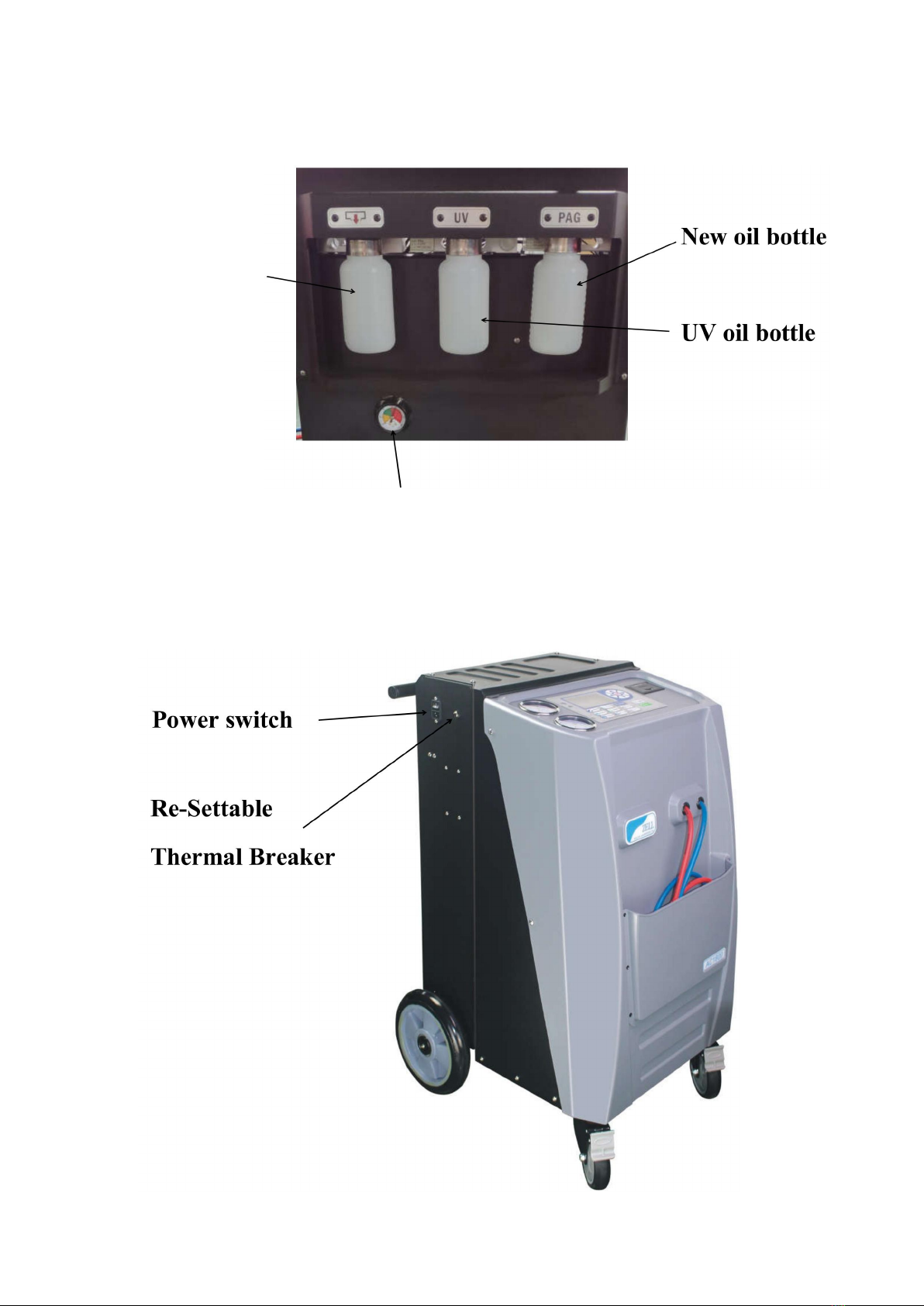
5 Overview of the Air-Con Service Station........................................................................9
6 First start up......................................................................................................................... 12
6.1
Setting up and switch up..............................................................................................................12
6.2
Putting into the bottles for new oil...............................................................................................13
6.3
Filling up the internal refrigerant container................................................................................ 13
7 Operation...............................................................................................................................19
7.1
Recovery..........................................................................................................................................20
7.2
Vacuum and vacuum test.............................................................................................................24
7.3
Oil injection.....................................................................................................................................27
7.4
UV injection...................................................................................................................................... 30
7.5
Recharge..........................................................................................................................................34
7.6
Fully auto..........................................................................................................................................39
7.7
Weight scale verification................................................................................................................. 44
7.8
Record print...................................................................................................................................... 46
7.9
Weight scale and Pressure sensor zero........................................................................................47
8. Service tasks.......................................................................................................................52
8.1
Inner tank refill............................................................................................................................... 52
8.2
Language select............................................................................................................................52
8.3
Weight unit..................................................................................................................................... 53
8.4
Other service................................................................................................................................53
9. Disposal................................................................................................................................54
9.1
Disposing of used fluids............................................................................................................... 54
9.2
Disposing of packaging material................................................................................................54
10 Trouble shooting............................................................................................................... 55
11 Technical data.................................................................................................................... 56
12 Spare Part list.....................................................................................................................56

2
1 About this operation manual
This operation manual describes the ZELL Air-Con Service Station
This manual is for those who have the required professional ability of
providing the maintenance service on vehicle air conditioning system.
This manual contains all the instructions necessary for safe and effective
operating of the air Conditioning service Station. Read this operation manual
carefully before putting the device into using for the first time.
Also note the following:
■ the operator should comply with the laws about the service of vehicle air-
conditioning by local government.
■ the operator should be familiar with basic technical information of vehicle
air- conditioning
■ Instructions from the refrigerant manufacturer
■ Instructions from the car manufacturer
■Any special instructions on servicing vehicle air conditioning systems which
applied at your company
Keep this operation manual in the tool box of Air-Con Service Station, so that
any information needed is always at your hand.

3
1.1 For illustrating the symbols in this operation manual
Format
Meaning
Example
button
Symbols used on the device
Press
„BOLD”
Display messages
„LANGUAGE”
■Text
■Text
List in any order
■Pressure monitor
■Pressure relief valves
1. Text
2. Text
3. Text
Actions to be carried out in the
order shown
1. Connect the device.
2. Switch on the device.
3. Press the selection button.
Text (1)
Part number
Use the buttonpad (7) to enter
the data.
Text (A)
Part designations which refer to
the diagrams shown in the
section describing the work
Remove the filter cartridge (E)
on the left side.
Risk of damage to the machine or other material damage
Special information for using the device effectively

4
2 Scope of delivery
The Air-Con Service Station and its accessories are carefullychecked
before shipping.
After delivery, please check all the parts listed below are present
and undamaged.
If any part is missing or damaged, notify the company responsible
for transport immediately
AC1800
Air-Con Service Station
Blue hose with coupling for LP connection and red hose with HP connection
2 Containers for new oil
Container for used oil
Inner tank refill connector
Power cord
operation manual

5
3 Safety
3.1
General safety instructions
Read this operation manual carefully before starting up the
Air-Con Service Station for the first time
Please note the following:
■ the operator should comply with the laws about the service of vehicle air-
conditioning by the local government.
■ the operator should be familiar with technical information of vehicle air-
conditioning
■
Information form the refrigerant manufacturer
■
Any special instructions on servicing vehicle air conditioning systems
which applied at your company
And also please pay attention to these massages:
→ Risk of injury, This equipment should only be operated by certified
personnel.
→Only use the device for its intended purpose. To reduce the risk if injury,
care should be taken when moving this equipment.
→ For indoor use only.
→ Wear personal safety equipment (goggles and gloves) and avoid
touching refrigerant, as this can cause chilblains to your body.
→ Use only ZELL approved storage cylinder,part NO.5150998 with this
refrigerant recovery unit.
→ Only use genuine R1234yf refrigerant .If other refrigerants are mixed
in, it can damage the Air-Con Service Station and the vehicle air condition
system.
→ The Equipment has mistake inside or a wrong operation of the
equipment will cause a possible contamination of refrigerant in equipment
and it’s cylinder. Contaminated R134-a DO NOT USE,MUST BE
REPROCESSED.
→ Only use correct type refrigerator oil (refrigerant oil) used with the
R1234yf.If other oil are mixed in, it can damage the vehicle air condition
system.
→This equipment should be used in locations with mechanical ventilation
that provides at least four air changes per hour or the equipment should be
located at least 18(457 mm) in above the floor.Do not inhale refrigerant

6
gas . Although the gas is non-toxic, it displaces the oxygen you needed.
→ This equipment should NOT be used in the vicinity of spilled or open
containers of gasoline.
→ To reduce the risk of fire.connect only to a circuit provide with 20
amperes maximum branch circuit over current protection in accordance
with the National Electric Code,ANSI/NFPA 70.
→ Avoid the use of an extension cord because the extension cord may
overheat. However,if you must use an extension cord,the cord shall be
NO.14 AWG minimum.
→ Each time before you start up the device or add gas to the Air-Con
Service Station, first check whether the device is undamaged and
components are not lost.Do not start up the Air-Con Service Station if it is
damaged.
→ Always use the main switch of the Air-Con Service Station for
switching it on and off. Do not leave the device unattended when it is
switch on.
→ Before you shut down the Air-Con Service Station, make sure that the
selected program has ended. Otherwise refrigerant can leak.
→ Avoid breathing A/C refrigerant and lubricant vapor or mist,exposure
may irritate eyes,nose and throat. To remove refrigerant from the A/C
system, Use only equipment certified for the type of refrigerant being
removed to meet the requirements of SAE J2210(HFC-R1234yf recycling
equipment.) Additional health and safety information may be obtained from
refrigerant manufactures.
→ Do not pressure test or leak teat equipment and/or vehicle air
conditioning system with compressed air. Some mixtures of air and
refrigerant have been shown to be combustible at elevated pressures.
these mixtures,if ignited, may cause injury ot property damage.Additional
health and safety information may be obtained from refrigerant
manufacturers.
→ Recover the service hoses before you release connections.
→ Do not make any modifications to the Air-Con Service Station.

7
3.2
Warnings on the Air-Con Service Station
Be careful
Observe the operation manual.
Protect the device against rain
Wear gloves when handling refrigerants.
Wear goggles when handling refrigerants.
Horizontal holding the station
Caution for fire
3.3
Safety devices
■
Pressure monitor: switch the compressor off if the normal
operation pressure is exceeded.
■
Tank with pressure relief function: additional safety mechanism releaser
to protect lines or vessels from bursting if the pressure continues to rise
despite the action of the pressure monitor.

8
4 Proper use
The Air-Con Service Station is intended for performing maintenance on vehicle
air-conditioning systems. The device is designed for commercial use.
The Air-Con Service Station may be operated by persons who have the required
professional ability for servicing air-conditioning systems.
This Air-Con Service Station may only be used to service vehicle
air-conditioning systems in which R1234yf refrigerant is used.
ZELL assumes no liability for damage resulting from the following:
■
Use for purposes more than those described in this operation manual.
■
Modification to the Air-Con Service Station without the permission of ZELL
■
Damage to the device resulting from external influences.
■
Incorrect operation

9
5 Overview of the Air-Con Service Station
Used oil bottle
Pressure gauge for working tank

10
USER COMMUNICATION INTERFACE:
Recovery button : to recover the A/C refrigerant into the inside
working tank,also it used for a number and character input.
Vacuum button : to extract Non-condensable gases from A/C
system,also it used for a number and character input.
New oil button : to inject new oil into vehicle A/C system.also it
used for a number and character input.
UV inject button : to inject UV into vehicle A/C system.also it used
for a number and character input.
Recharge button : to refill refrigerant into vehicle A/C system.also
it used for a number and character input.

11
Auto button: one press operation for all steps
automatically.also it used for a number and character input.
Weigh Scale Verification: check scale weight accuracy.also it
used for a number and character input.
Record print button: Car plate input and Print receipt (printer is
an option item),also it used for a number and character input.
Function button : it allows to start the other service
operation.also it used for a number and character input
Input buttons: to adjust numerical value. Up and right button
are for increase value,left and down is for decrease.
Up and Down also used for page up and page down.
Start button : it allows to start the operation step.
Stop button : it allows to cancel the operation step.
OK button : Confirmation for selected operation.

12
Page down
Info:
Example 1, when input the workshop info.
If the desired character is on below page, Press for “1”input,like wise,
Press for “8”input,and so on.
On this page you can select whatever number you want.

13
If the desired character is not on the page,press page up or page down, check the
character showing on the LCD,
For example, if you want you input “D” press ,and press
for“C”,and so on.

14

15
Example 2, when input the gas amount in Recharge function.
Each press of the adjust button, the gas amount is showed below:
All the other adjustment like in OIL INJECT,VACUUM, is the same conception.

16
1 First start-up
1.1
Setting up and switching on
110v 60Hz Power supply must be firmly grounded. If not,it will
cause the weight scale a incorrect operation;it also may cause an
injury to operators from an electric shock.
1. Place Air-Con Service Station to the workplace and lock the front
casters.
Before operation the device must be on a level, flat surface so that
measurement can be made correctly.
2. Plug in the Air-Con Service Station .
3. Switch on the Air-Con Service Station.it come to the standby mode:
Maintenance of Drier

17
When at standby mode keep pressing

18
6.2
Installing in the bottle for new oil
Unscrew the refrigerant oil bottle, put about 150 ml new oil in and screw it back
to the device.
6.3
Filling up the working tank
When the Air-Con Service Station is started for the first time, the internal
refrigerant container is suggested be filled gas with at least 6 kg from an
external refrigerant cylinder.
Also note the instructions on the refrigerant bottle.
The current refrigerant quantity is shown in the standby mode.
■ Refrigerant bottles without a rising pipe: These refrigerant bottles have
one connection. When filling the Air-Con Service Station, the connection
port must be at the bottom (turn the bottle upside down).

19
RED ONE IS THE VAPOR PORT OF THE SOURCE TANK
Only LIQUID refrigerant is recommended.
■ For other type of source tank, be sure that Only Liquid port should be
connected to the refill adapter.
BLUE ONE IS THE LIQUID PORT OF THE SOURCE TANK
1.On standby mode,put the refill connector to the refrigerant bottle and fix it,then
join the LP adapter with the low pressure hose(blue) to the connector,
open the adapter, open the bottle valve and up side down it.press
button, the LCD will show
2. Press to confirm. Follow the instructions on the display.
Other manuals for AC1800
1
Table of contents
Other Zell Service Equipment manuals
Popular Service Equipment manuals by other brands

XPOtool
XPOtool 30155 user manual

Sealey
Sealey AS2500 instructions

LTR
LTR BSG 03_230 manual

TECALEMIT
TECALEMIT 3000XB Installation, operation and maintenance instructions

Powerfix Profi
Powerfix Profi PFRS 1.5 A2 operating instructions

Accumulators
Accumulators AI-CG3-3KT-SS Installation, operation & care manual